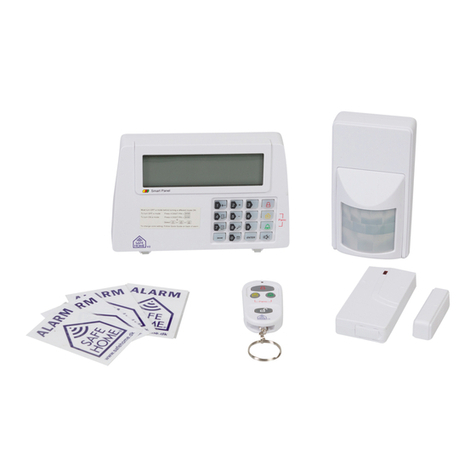
SAFE HOME WS500S User manual

UK - User Guide
Wireless Security System WS500S
WS500S

www.safehome.dk
2
Table of Content
1. Getting Started .....................................4
CAUTION! 4
1.1 Introduction to the System 4
1.2 Items included with the System 4
1.3 Introduction to the Smart Panel 5
1.4 Introduction to the Smart Panel Sound Alert and Backlight 5
2. Installing the Wireless Security WS500S ................6
2.1 Installing the Control Panel 6
Note 6
2.2 Powering up the Control Panel 6
2.3 Understanding the Battery and AC Adaptor icon 7
3. Using the Wireless Security System WS500S ............7
3.1 Programming your new 4-Digit PIN 7
3.2 Panic Signal without a Siren 8
3.2.1 Panic Signal 8
3.3 Operating different Modes 8
3.3.1 STANDBY Mode 8
3.3.2 ARM Mode 8
A. Arming the System 8
B. Disarming the System 9
C. Zone Settings 10
D. Triggers in ARM Mode 10
3.3.3 ALERT Mode ...............................11
A. Entering ALERT Mode 11
B. Exiting the ALERT mode 12
C. . Zone Settings 12
3.3.4 HOME Mode ...............................13
A. Entering the HOME mode 13
B. Exiting the HOME mode 13
C. Zone Settings 14
4. Installing the Sensors ..............................15
4.1 Introduction to the Sensors 15
4.2 Installing the Sensors 15
4.2.1 Installing the Door/Window Sensor 15

www.safehome.dk
3
A. Powering up the the Door/Window Sensor 15
B.Installing the Door/Window Sensor 16
C. Mounting with the Double-Sided Adhesive 16
4.2.2 Installing the Motion Sensor 16
A. Powering up the Motion Sensor 16
B. Installing the Motion Sensor 16
C. Walk Test 17
D. Mounting with double sided tape 18
E. Mounting using Screws 18
4.2.3 Enrolling the Remote Control onto the Smart Panel 18
4.2.4 Deleting a Remote Control from the Smart Panel 19
4.2.5 Checking remote ID 20
4.3 House Security Code and Zone Code Settings 21
5. Adaptation of system functions.......................22
5.1 Adjusting Exit Delays 22
5.2 Adjusting Entry Delays 22
5.3 Adjusting the Alarm Duration 23
5.4 Muting the Audible Countdown 23
5.5 Tamper protection for the control panel 23
6. Troubleshooting ...................................24
6.1 FAQ 24
6.2 Troubleshooting 25
AC Power Failure: 25
System Battery Failure: 25
Sensor Failure: 25
6.3 Alarm System Limitations 25
7. Generel Information ................................26
7.1 Product Information 26
7.2 Specifications 26
7.2.1 Smart Panel 26
7.2.2 Key Fob Remote 26
7.2.3 Door/Window Magnetic Sensor 26
7.2.4 Motion Sensor 26
8. Disclaimer........................................27

www.safehome.dk
4
1. Getting Started
CAUTION!
Difficulty in disarming the Smart Panel in alarm mode may occur when it is powered by
battery alone. This is not a malfunction, and can be resolved by the use of a fresh 9V bat-
tery and a properly plugged in DC source from the AC/DC adaptor included.
Remove the battery cover on the Smart Panel and remove the small red / black / yellow
wire with battery and press the button. This was part of the package and is no longer
needed. Please note that the plug should be removed from the Smart Panel. The wires
must not be torn.
1.1 Introduction to the System
The Wireless Security System WS500S is a high quality security system combined with
user-friendly features that allows you to know the state of security of your home at all
times. The System is managed by a
Smart Panel, which gathers information
from wireless sensors placed inside
and at the entry points of your home.
If the Smart Panel detects a security
breach, you will be alerted via indicator
lights and sounds. For installation and
proper use of the Smart Panel, please
familiarise yourself with this User Guide
1.2 Items included with the System
Please check that all of the following items were included in the package before installing
the System:
• Smart Panel
• Key Fob Remote
• Door/Window Sensor
• Motion Sensor
• AC Adaptor for Smart Panel
• Double-Sided Adhesive for Door/Win-
dow sensor
• Screws & Screw Jackets
• Mounting Bracket for Motion Sensor
• Mounting Template
• Quick Start Guide
• User Guide

www.safehome.dk
5
1.3 Introduction to the Smart Panel
9V DC INPUT port For AC Adaptor
Siren output 120dB
Battery Compartment: For 9V Alkaline Battery Backup battery
4 x Pin Header, 4 x Jumper For setting of house code
Reset knap If you forget the 4-Digit PIN, press “Reset” button and
enter factory default PIN “ 1 2 3 4 ” followed by
to restore factory setting.
1.4 Introduction to the Smart Panel Sound Alert and
Backlight
MODE Sound (at alarm) Light (at alarm)
1 ARM Siren - 60 sec Red light flashes with triggered zone
indication. To stop- enter your 4-Digit PIN and
press
2 HOME Sirene - 60 sec Red light flashes with triggered zone
indication. To stop- enter your 4-Digit PIN and
press
Ring-Ding-Dong x 1 Green light flashes with triggered zone
indication. To stop- enter your 4-Digit PIN and
press
3 ALERT Ring-Ding-Dong x 1 Green light flashes with triggered zone
indication. To stop- enter your 4-Digit PIN and
press
4 STANDBY Silent Yellow backlight ON for 10 secs. after enter
into STANDBY mode
The siren can also be switched off using the remote control button to open the padlock.

www.safehome.dk
6
2. Installing the Wireless Security WS500S
2.1 Installing the Control Panel
Choose location of the control panel:
Note
• The panel must have 220V power, so it should be located near a power outlet.
• The panel must be easily accessible for battery replacement and operation.
• The panel should not be placed near doors or windows where intruders have easy
access to it.
• The panel should not be placed close to the very hot devices (ovens, stoves, etc.) or
near devices that may interfere with the wireless signal.
• The panel must not be exposed to water.
When the location of the Smart Panel is selected, you are ready to connect the system.
2.2 Powering up the Control Panel
Unscrew the battery compartment and remove the cover. Take out the LED demo socket,
and insert a new battery noting the polarity as shown in the diagram below. Plug in the
AC adaptor to the Smart Panel and connect it to a wall socket. Replace the cover and the
screw.
Step Description Note
1 Insert 9V Alkaline
backup battery
You will hear one beep and the backlight will blink
within 1 second (Yellow>Red>Green>Yellow)
The Smart Panel will display the below image:
The Smart Panel will enter “STANDBY” mode after the
automatic self-checking is complete. Then will
appear on the LCD screen.

www.safehome.dk
7
2.3 Understanding the Battery and AC Adaptor icon
Battery icon
Full
High
Middle
Low
The battery icon shows when the AC power supply is un-
plugged or interrupted.
9V battery functions as BACK UP and the symbol
means LOW BATTERY, the LCD Backlight flashes yellow for
30 sec. and will blink until the new battery is replaced
or the AC power supply is plugged in.
AC adaptor icon When the AC adaptor to the Smart Panel is connected to a
wall socket, the AC symbol will appear.
The backlight will be ‘ON’ for 10 secs while the AC adapter
connects to the power supply.
3. Using the Wireless Security System WS500S
3.1 Programming your new 4-Digit PIN
Step Keys Description Note
1 You must be
in STANDBY
mode before
programming
your new 4-digit
PIN
To make sure you are in STANDBY
mode:
Enter the default 4-digit PIN + :
Press , the symbol disappears
from the screen.
2 Programming
your new 4-digit
PIN
Press then to set the new PIN
The Smart Panel will display the below
image :
34-digit PIN + Enter your new
4-digit PIN Enter the new 4-digit PIN
44-digit PIN + Re-enter new
PIN for final
confirmation
Re-enter the new 4-digit PIN
Press for final confirmation.
One beep indicates that you entered
a valid PIN, two beeps indicate that an
invalid operation was performed.

www.safehome.dk
8
3.2 Panic Signal without a Siren
If you are forced to disarm the System, enter the Duress Password to stop the siren from
sounding; the Smart Panel will silently transmit the alarm signal to the optional response
devices (Auto Dialer, Wireless Dialer/Control & Outdoor Bell Box) for emergency help.
Duress Password:
Enter PIN +
3.2.1 Panic Signal
Pressing + buttons together on the Keypad / Key Fob Remote for instanta-
neous emergency response
3.3 Operating different Modes
The system consists of 4 Operating Modes (STANDBY, ARM, ALERT, and HOME) to suit
the user’s needs. You may select from the 4 modes to be applied to the sensors.
3.3.1 STANDBY Mode
If in Standby, the Smart Panel is prepared for mode selection.
3.3.2 ARM Mode
If in Arm Mode, the Smart Panel alarm will sound and the Smart Panel (All in RED) flashes
every 1.5 seconds when the system is triggered.
ARM mode default setting::
Zone Status (MODE)
Door/Window Sensor 1 ARM
Motion Sensor (PIR) 8 ARM
A. Arming the System
On the Smart Panel: First make sure the Smart Panel is in STANDBY mode by following
steps below for arming the system:
On the Key Fob Remote: Press to activate.

www.safehome.dk
9
Step Keys Description Note
1PIN + You must be in
STANDBY mode
before
programming
To make sure you are in STANDBY
mode:
Enter your PIN
Press , the symbol disap-
pears from the screen.
2 PIN
+ +
ARM mode There is a 30 seconds exit delay
time with a visual and sounds count
down before the system is armed.
(Press Mute to disable the count
down sounds, Press Mute again to
resume the sounds)
If the Zone is enabled, a number will
appear as displayed in the image
below:
The System will then enter ARM
mode after 30 seconds.
B. Disarming the System
On the Smart Panel: Enter your 4-Digit PIN followed by to disarm the system.
On the Key Fob Remote: Press to disarm the system.

www.safehome.dk
10
C. Zone Settings
Programming each zone in ARM mode:
Step Keys Description Note
1PIN + You must be in
STANDBY mode
before
programming
To make sure you are in STANDBY
mode:
Enter your PIN
Press , the symbol disap-
pears from the screen.
2PIN + Enter 4-DIGIT PIN
for setting followed
by
The Smart Panel will display the
below image:
3+ Press the two but-
tons in succession
to select the zones
to be activated dur-
ing ARM
Toggle 1, 2, 3, 4, 5, 6, 7, 8 to turn
each zone ON or OFF
If no number appears, the zone is
turned OFF
The Smart Panel will display the
below image
4Complete the set-
ting
After the setting is completed, return
the Smart Panel to STANDBY for
mode selection.
D. Triggers in ARM Mode
Example: Zone 1 trigger
Step Description Note
1 System trigger
One beep indicates that the system is triggered
2 Entry delay 30
seconds
There are 30secs. of entry delay time with visual count
down for disarming.
Once an intrusion has occurred (zone triggered under
ARM status), alarm siren will sound 1 minute and the
Smart Panel (All in RED) flashes every 1.5 seconds with
triggered zone indication until the system is disarmed.

www.safehome.dk
11
Step Description Note
3 Smart Panel (All in RED) flashes every 1.5 seconds with
triggered zone indication until the system is disarmed.
To disarm the system, enter the 4-Digit PIN or press
on the remote control to exit the current mode.
4 Return to ARM
Mode after the
initial triggering
After this initial triggering, the alarm will trigger again
immediately upon opening of the door without the entry
delay.
3.3.3 ALERT Mode
If in Alert mode, the Smart Panel chime will sound and the Whole Smart Panel (All in
GREEN) flashes every 1.5seconds with triggered zone indication when the system de-
tects a intruder in the protected area.
ALERT mode default setting:
Zone Status (MODE)
Door/Window Sensor 1 ARM
Motion Sensor (PIR) 8 ARM
A. Entering ALERT Mode
On the Smart Panel: First make sure the Smart Panel is in STANDBY mode by following
steps below for entering into ALERT mode:
On the Key Fob Remote: Press to activate.
Step Keys Description Note
1PIN + You must be in
STANDBY mode
before
programming
To make sure you are in STANDBY
mode:
Enter your PIN
Press , the symbol disap-
pears from the screen.
2 PIN
+ +
ALERT mode The System will enter ALERT Mode.
If the Zone is enabled, a number will
appear as displayed in the image
below:

www.safehome.dk
12
B. Exiting the ALERT mode
On the Smart Panel: Enter your 4-Digit PIN followed by f to exit ALERT mode.
On the Key Fob Remote: Press to exit ALERT mode.
C. . Zone Settings
Programming each zone in ALERT Mode
Step Keys Description Note
1PIN + You must be in
STANDBY mode
before
programming
To make sure you are in STANDBY
mode:
Enter your PIN
Press , the symbol disap-
pears from the screen.
2PIN + Enter 4-DIGIT PIN The Smart Panel will display the
below image:
3+ Press the two but-
tons in succession
to select the zones
to be activated dur-
ing ALERT
Toggle 1, 2, 3, 4, 5, 6, 7, 8 to turn
each zone ON or OFF
If no number appears, the zone is
turned OFF
The Smart Panel will display the
below image:
4Complete the set-
ting
After the setting is completed, return
the Smart Panel to STANDBY for
mode selection.

www.safehome.dk
13
3.3.4 HOME Mode
The system is pre-programmed to work with the default settings already when the pack-
age is opened. These settings can be adjusted to your own needs and desires. The home
setting allows you to set the Smart Panel to have some zones connected in ARM mode,
some zones connected ALERT mode and some zones completely disconnected.
HOME Mode factory settings for devices in the package:
Zone Status (MODE)
Door/Window Sensor 1 ARM
Motion Sensor (PIR) 8 ARM
A. Entering the HOME mode
On the Smart Panel: First make sure the Smart Panel is in STANDBY mode by following
steps below for entering into HOME mode:
On the Key Fob Remote: Press to activate.
Step Keys Description Note
1PIN + You must be in
STANDBY mode
before
programming
To make sure you are in STANDBY
mode:
Enter your PIN
Press , the symbol disap-
pears from the screen.
2 PIN
+ +
HOME mode Then System will enter HOME mode
If the Zone is enabled, a number will
appear as displayed in the image
below
Black number indicates ALERT
mode for a zone
White number Indicates ARM mode
for a zone
Blank indicates the zone is turned
OFF, number will not appear
B. Exiting the HOME mode
On the Smart Panel: Enter your 4-Digit PIN followed by to exit HOME mode. .
On the Key Fob Remote: Press to exit HOME mode.

www.safehome.dk
14
C. Zone Settings
VProgramming each zone in HOME Mode:
Step Keys Description Note
1PIN + You must be in
STANDBY mode
before
programming
To make sure you are in STANDBY
mode:
Enter your PIN
Press , the symbol disap-
pears from the screen.
2PIN + Enter 4-DIGIT PIN Skærmen vil vise nedenstående:
3+ Press the two but-
tons in succession
to select the zones
to be activated dur-
ing HOME
Toggle 1, 2, 3, 4, 5, 6, 7, 8 to turn
each zone in different mode.
Black number indicates ALERT
mode for a zone
White number Indicates ARM mode
for a zone
Blank indicates the zone is turned
OFF, number will not appear
4Complete the set-
ting
After the setting is completed, return
the Smart Panel to STANDBY for
mode selection.

www.safehome.dk
15
4. Installing the Sensors
4.1 Introduction to the Sensors
This package includes 2 wireless Sensors and 1 Key Fob Remote, which have a pre-pro-
grammed default setting that begins working immediately once the battery is activated. It
is advisable to install the main package first and then personalise the settings once the
System is functioning properly. This section should help you to change the System set-
tings in order to create a more personalized home environment.
4.2 Installing the Sensors
First, determine the location of the sensors.
• The Sensors should not be easily accessible.
• The Sensors should be placed in the most vulnerable rooms or near key entry points.
• The Sensors should not be placed near extreme temperature sources (ovens, stoves
etc.) or near large metal objects that could interfere with the wireless performance.
• If necessary, change to a different location for better RF performance
Once you have selected a location for the Sensors, you are ready to begin powering up
the System.
4.2.1 Installing the Door/Window Sensor
The Door/Window Sensor consists of two pieces. The sensor detects when a door or a
window is opened. The two parts are fastened near the door or the window. One part
functions as the transmitter and the other as the magnet. Once the Sensor is installed,
any abnormality in the circuit will trigger an alert message that is transmitted to the Smart
Panel. The Door/Window Sensor is pre-programmed in Zone 1; however, the settings can
be adjusted according to your needs. (See 3.3 & 4.3 Zone Settings)
A. Powering up the the Door/Window Sensor
Remove the battery cover; insert new batteries noting the polarity as shown in the dia-
gram below; replace the cover. (Requires 2 - alkaline AAA batteries)
Low Battery indication, If the batteries need to be replaced, a slow flashing of the RED
LED will indicate low battery
Motio

www.safehome.dk
16
B.Installing the Door/Window Sensor
• Attach the transmitting unit (the main unit) on a solid
surface such as the door or windowsill.
• Mount the magnet onto a moving surface such as a
door or a window.
• Send ago marked with “>/<”. These characters must
be level with each other.
• The transmitter and magnet must not be more than 5
mm apart when the door / window is closed.
• Make sure that the devices are installed correctly by
opening the door / window. When the contact is bro-
ken, the little lamp on the battery pack light briefly and
indicates that a change is detected. If the light does not
appear, the units are mounted too far apart.
C. Mounting with the Double-Sided Adhesive
• Ensure the mounting surface is clean.
• Peel back one layer of the protective film and attach it to the transmitter.
• Peel back the remaining layer of protective film and press the transmitter firmly in place
against the mounting surface until firmly attached.
• Repeat to attach the magnet.
4.2.2 Installing the Motion Sensor
The wireless alarm system comes with 1 sensor described as a passive infrared sensor
(PIR).
A. Powering up the Motion Sensor
Remove the battery cover; insert a 9V battery noting the
polarity as shown in diagram below; replace cover.
B. Installing the Motion Sensor
• First, determine the location of the Motion Sensor.
• The Sensor should not be easily accessible.
• The Sensor should be placed in the most vulnerable rooms or near key entry points.
• Place the Sensor on a sturdy surface between 1.8m to 2.4mm (6ft to 8ft) from the floor.
• The Sensor should not be placed near extreme temperature sources (ovens, stoves
etc.)

www.safehome.dk
17
• The Sensor should not be placed in direct sunlight.
• Do not install the Sensor outdoors or behind partitions.
• If necessary, change to a different location for better RF performance
Room sensor can be mounted with either screws or double-sided tape.
IMPORTANT! The Motion Sensor is designed with a power saving program. The
Motion Sensor will remain inactive for 3 minutes after each detection. Thus, during
system set up, please bare in mind of this feature during system set up.
The sensitive of the motion sensor is adjustable. Change the setting by placing the
connector on either the “High”, “Middle” or “Low” position. When the sensitivity is set to
“Low”, more movement is required to trigger the sensor. It is recommended to set the
sensitivity to “Low” and perform a “Walk Test” (Described in part D). If the walk test result
is satisfactory, the sensitivity does not require further adjustment. If the walk test result
shows the sensitivity is too low, then you can change the sensitivity setting to “Middle” or
“High” accordingly. Please perform the walk test after changing the sensitivity setting.
C. Walk Test
After mounting the sensor at the desired location, it is important to perform a walk test in
order to determine if the sensor is covering the correct area (up to 6 m).
In order to adjust the monitored area, the
angle of the sensor can be adjusted. If you
want to monitor a small area, turn sensor
down to the floor. If a larger area is required
turn sensor max. 12° up. This provides maxi-
mum range.
Always disconnect the call unit or sirens before “walk test” is performed.
Go in to the area the sensor should monitor. If a red light does not appear in the sen-
sor, the angle should be adjusted. Perform “walk test” again after 3 minutes. Repeat the
process until your motion is detected. Please note that there should be no movement in
the area of 3 minutes before test.
Tips: The sensor must not be directed against direct sunlight may not be placed near
heat or cold units (Air-climate plants, fans, stoves, heaters, etc..), As this may cause false
alarms.

www.safehome.dk
18
D. Mounting with double sided tape
• Make sure the surface is clean.
• Take the film from one side of the tape and attach to unit.
• Take the film of the other side and fix the unit on the mounting surface.
E. Mounting using Screws
• Hold the enclosed mounting template against the wall at the selected location and
mark the points for drilling.
• Drill the holes and insert wall plugs.
• Attach the bracket to the mounting surface with the screws provided.
• Attach the Motion Sensor to the mounting bracket.
4.2.3 Enrolling the Remote Control onto the Smart Panel
The Remote Control devices can be enrolled (added onto the system) as follows.
Step Keys Description Note
1PIN + You must be in
STANDBY mode
before
programming
To make sure you are in STANDBY
mode:
Enter your PIN
Press , the symbol disap-
pears from the screen.
2+ Press the buttons
on control panel to
enrol the remote
controls into the
system.
After pressing
any button on the
remote to regis-
ter and get an ID
number on remote
control.
LCD display flashes the ID no. of
the remote to be enrolled e.g. when
enrolling the first remote ID no. “01”
will flash. Once the first remote is
enrolled the “02” will flash ready
for a second remote to be enrolled
(One beep indicates that the remote
was enrolled to the Smart Panel
successfully)
Note: It is recommended that the
ID No. is marked on the remote in
case it needs to be deleted at a later
stage
3Complete the set-
ting
After the setting is completed, return
the Smart Panel to STANDBY for
mode selection.

www.safehome.dk
19
4.2.4 Deleting a Remote Control from the Smart Panel
Step Keys Description Note
1PIN + You must be in
STANDBY mode
before
programming
To make sure you are in STANDBY
mode:
Enter your PIN
Press , the symbol disap-
pears from the screen.
2+ Press the keys on
control panel to
go to deletion.
Then input ID
number on remote
control to be re-
moved.
LCD display flashes the total num-
ber of remote currently enrolled to
the system
(e.g. If the Smart Panel has 3 re-
motes enrolled the LCD display will
flash “03”)
Input the remote ID no. (e.g. “02”)
for the remote you wish to delete
(Inputting “00” will delete all remote
controls)
LCD display will then flash the total
number of remotes enrolled after
deletion
(One beep indicates that the remote
was successfully deleted from the
Smart Panel)
3Complete the set-
ting
After the setting is completed, return
the Smart Panel to STANDBY for
mode selection.

www.safehome.dk
20
4.2.5 Checking remote ID
Step Keys Description Note
1PIN + You must be in
STANDBY mode
before
programming
To make sure you are in STANDBY
mode:
Enter your PIN
Press , the symbol disap-
pears from the screen.
2+ Press the keys on
control panel to
access the control
by ID status. Then
press any button on
the remote control
to control the
remote ID
When the control panel is in this
status, the screen will flash with the
total number of remote controls that
are connected.
For example, the screen flashes
“03” if there are 3 connected
remotes. ID of a specific remote
control is displayed on the
press any button on remote control.
Doing so will control panel screen
displays the remote ID.
(One beep indicates that the proce-
dure is performed correctly.)
3Complete the set-
ting
After the setting is completed, return
the Smart Panel to STANDBY for
mode selection.
Table of contents
Languages:
Other SAFE HOME Security System manuals

SAFE HOME
SAFE HOME WS209 User manual

SAFE HOME
SAFE HOME WS110-V2 User manual

SAFE HOME
SAFE HOME WS210 User manual

SAFE HOME
SAFE HOME CLI 810 HF User manual
SAFE HOME
SAFE HOME PT700 User manual

SAFE HOME
SAFE HOME WS200X User manual

SAFE HOME
SAFE HOME WS500S-V2 User manual
SAFE HOME
SAFE HOME HTZSAFE 805A+MC User manual
Popular Security System manuals by other brands

Vicon
Vicon V8300H-S Instructions for installation and operation

My ADT
My ADT ITI Concord Express Getting to know

Sony
Sony CCTV Systems Catalog

Vip-Vision
Vip-Vision Solar Surveillance SLR-A75 Series installation guide

Maretron
Maretron ALM100-01 user manual

MEGATRONIX
MEGATRONIX Viking VS 315 Installation and operation manual