Safelab AIRONE 1000R User manual

Doc no: M18 Issue no: 07 Created: 24/08/09
1
INSTRUCTION MANUAL
Code: 1000R, 1200R, 1500R, 1800R
AIRONER (VAV) Range of
Filtration Fume Cupboards
SAFELAB SYSTEMS LTD
Unit 29 Lynx Crescent Weston Super Mare BS24 9BP UK
Telephone: 01934 421340 Fax: 01934 641569
WWW.SAFELAB.CO.UK

Doc no: M18 Issue no: 07 Created: 24/08/2009 2
FOREWORD
This manual has been prepared to give guidance in the use of the following Recirculatory,
Filtration Fume Cupboards:
Code: Description.
1000R AIRONE1000-R (VAV) Filtration Fume Cupboards
1200R AIRONE1200-R (VAV) Filtration Fume Cupboards
1500R AIRONE1500-R (VAV) Filtration Fume Cupboards
1800R AIRONE1800-R (VAV) Filtration Fume Cupboards
This manual contains the information required to ensure optimum and free operation of the
AIRONER range of Filtration Fume Cupboards.
Service and maintenance operations should only be undertaken by SAFELAB Service
Engineers or their authorised agents.
Details of Service Contracts, along with information on these and other products is available
on request from:
SAFELAB SYSTEMS LTD
Unit 29 Lynx Crescent
Weston Super Mare
BS24 9BP
Telephone - 01934 421340
Fax - 01934 641569
Website: - http://www.safelab.co.uk

Doc no: M18 Issue no: 07 Created: 24/08/2009 3
INDEX
Page Contents
4 - 5 Principle of Operation
6 - 7 Specification
7 - 8 - 9 Installation and Assembly Instructions
10 Key Component Parts
11 Operating Instructions
12 Maintenance/Cleaning
Appendices
13 I. Fitting of the Main Carbon Filter.
14 II. Pre-filter Replacement.
15 - 16 III. Monitoring the Airone R.
DIY Filter Monitoring.
16 - 17 IV. Instructions for face velocity measurements.
Airone R Examination Record.
18 V. Instructions for Filter saturating testing.
19 VI. Main Block Wiring Diagram.
20 - 21 VII. Control System/Calibration Procedure.
22 VIII Siting Locations for Airone R
23 XI. E.C. Declaration of Conformity.

Doc no: M18 Issue no: 07 Created: 24/08/2009 4
PRINCIPLE OF OPERATION
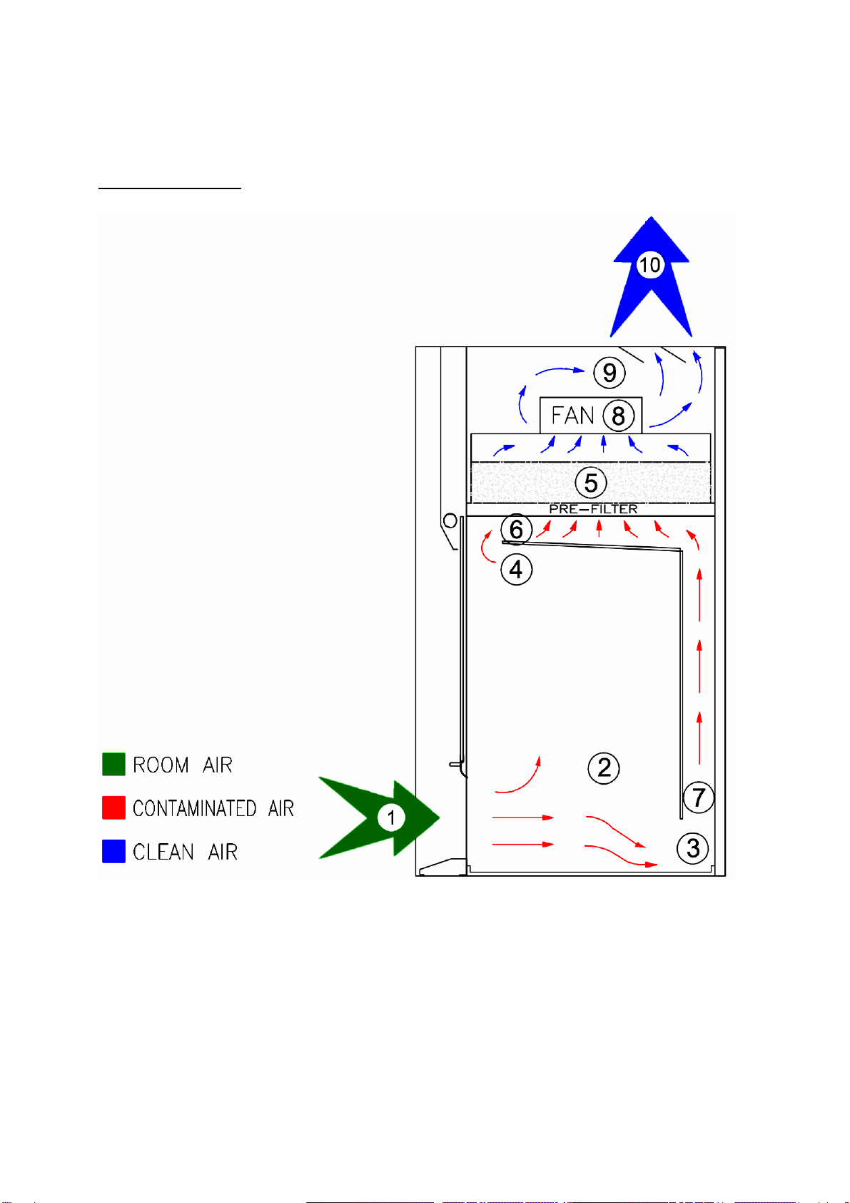
(1) Recirculatory Mode of Operation (see diagram on following page)
Air is drawn in through the front opening (1) at a velocity ensuring containment of any
contaminants generated within the work area (2).
The operator can determine the required aperture by sliding the glass sash up to a maximum
determined by the sash stop.
The contaminants from area (2) are drawn either upwards as in the case of lighter than air
volatiles (4), or drawn across the worksurface to the secondary extract slot created by the
back baffle, as in the case of heavier than air volatiles or particulates (3).
The combinations of extract slots (6) and (7) ensure that all contaminants entrained in the
airflow are effectively transferred to the filter (5).
The filter(s) (5) combine large surface areas with a deep bed depth to ensure efficient
filtration of contaminants. Clean filtered air is then drawn through the fan(s) (8) and after
passing into the dispersal chamber (9) is exhausted via the louvres (10).
The relatively high pressure drop across the carbon filters ensures even flow through the
filter and exceptionally uniform saturation.
AIRONE™ R Filtration Fume Cupboards present a combination of advantages and unique
features - ensuring the health and safety of operators by prevention of their exposure to
concentrations of toxic chemical compounds providing protection to their environment - in
line with British, European and US Federal Safety Standards.
Moving the vertical gliding safety glass upwards and downwards causes the fan to speed up
or slow down to give a constant face velocity. To avoid the unit alarming unnecessarily, the
sash should be moved slowly.
(2) Ducted - Vented Mode of Operation:
Should venting to outside atmosphere be required after removal of contaminants by efficient
filtration, the duct-work can be connected to the AIRONE Filtration Fume Cupboard via an
optional duct adapter top box fitted with a 250 mm dia. duct outlet and internal transition
adaptors fitted onto the fan(s). This Ducted Filtration Fume Cupboard will also protect
personnel and the environment outside the building - contributing to the overall reduction of
atmospheric pollution.

Doc no: M18 Issue no: 07 Created: 24/08/2009 5
Airone R airlfow:

Doc no: M18 Issue no: 07 Created: 24/08/2009 6
SPECIFICATION
Definition: AIRONEWork Stations are chemical Work Stations designed for the protection
of operators from gaseous or particulates contaminants produced within the
unit.
Application: Whenever the operator and the environment need to be protected from
gaseous or particulate contaminants.
Construction:Manufactured from epoxy coated mild steel and aluminium extrusions. The
transparent fume enclosure is constructed using laminated security glass.
Worksurface:Polypropylene worksurfaces are supplied as standard. A variety of worksurfaces
are available which include Solid Grade Laminates, Stainless Steel and Cast
Epoxy Resin.
Prefilters: Particle pre-filters with an efficiency of better than 97% for particles greater
than 0.3 micron (DOP test).
1000-R AIRONEWork Stations Size ‘RS’ (690 x 490mm) 1 Pre-filter
1200-R AIRONEWork Stations Size ‘B' (600 x 450mm) 2 Pre-filters
1500-R AIRONEWork Stations Size ‘B' (600 x 450mm) 2 Pre-filters
1800-R AIRONEWork Stations Size ‘B' (600 x 450mm) 3 Pre-filters
Main Filters:
1000-R AIRONEWork Stations Size ‘RS' (690 x 490mm) 1 Filter
1200-R AIRONEWork Stations Size ‘B' (600 x 450mm) 2 Filters
1500-R AIRONEWork Stations Size ‘B' (600 x 450mm) 2 Filters
1800-R AIRONEWork Stations Size ‘B' (600 x 450mm) 3 Filters
Safelab Systems offer a wide variety of filter types for different applications, please consult
your Operational Safety Log Book.
Supply: 1000-R AIRONE220-240V 50Hz - 1.4 A
1200-R AIRONE220-240V 50Hz - 2.4 A
1500-R AIRONE220-240V 50Hz - 2.4 A
1800-R AIRONE220-240V 50Hz - 4.0 A
Weight: 1000-R AIRONE98 Kg } Excluding filter
1200-R AIRONE126 Kg } Excluding filter
1500-R AIRONE140 Kg } Excluding filter
1800-R AIRONE180 Kg } Excluding filte
Specification continued

Doc no: M18 Issue no: 07 Created: 24/08/2009 7
Dimensions (in millimetres): Width x Depth x Height
1000-R AIRONEExternal 1000 x 760 x 1300
1000-R AIRONEInternal 950 x 550 x 780
1200-R AIRONEExternal 1200 x 760 x 1300
1200-R AIRONEInternal 1150 x 550 x 780
1500-R AIRONEExternal 1500 x 760 x 1300
1500-R AIRONEInternal 1450 x 550 x 780
1800-R AIRONEExternal 1800 x 760 x 1300
1800-R AIRONEInternal 1750 x 550 x 780
INSTALLATION AND ASSEMBLY INSTRUCTIONS.
(Only applies if cabinet is mounted on stand)

Doc no: M18 Issue no: 07 Created: 24/08/2009 8
Contents of Packaging (as standard).
- AIRONEFiltration Fume Cupboard complete
- One envelope containing Prefilters (these may in some instances be fitted in the unit)
- One bag containing:-
- Operational Safety Log Book.
- Operational Manual.
- Quality Control Certificate.
-Mains Lead.
-Allen Key.
Additional packages will include, if ordered, support stand, filters, ducting kits, etc.
Please note that for optimum performance it is advisable to site the AIRONEFiltration Fume
Cupboards as directed in the Operational Safety Log Book (ref.: BS:7258).
Space for free air circulation must be provided around the AIRONEFiltration Fume
Cupboard.
Place the AIRONEFiltration Fume Cupboard on the selected bench or stand.
Fitting the Filters
It is advisable to have another person available to assist
The following procedure should be followed:
-Ensure that power to the unit is switched off.
- Ensure that the front sash is at its lowest position.
-Unscrew the main front cover panel by removing the Allen screws to expose the main
filter housing aluminium cover plate, ensuring that the lighting plug is disconnected. If
possible have an assistant support the cover while this is done.
- Loosen screws and remove cover plate by sliding it up and out of the keyhole slots.
- The filter housing units each comprise of a combined motor and filter plenum
chamber.
-Unpack the Main Activated Carbon or HEPA filters and slide them gasket side
downward between the support guides for each main filter housing.

Doc no: M18 Issue no: 07 Created: 24/08/2009 9
Good filter seating is essential for optimum performance.
- When all filters are in place, tighten the clamping nuts firmly.
- One filter identification label will be supplied with the filter so that when the filter is
installed it is visible through the viewing window.
- Replace both the front cover panels and retaining screws, ensuring the lighting plug is
reconnected.
- Access to the pre-filters is made when the internal upper baffle is unfastened at the
front and allowed to fold down. Access does not interrupt the seating of the main
filters.
- Carefully unscrew the knurled nuts holding the internal baffle in position and allow it
to fold down to expose the pre-filter carrying frames.
- Unfasten the knurled nut holding the lower pre-filter carriers and allow them to fold
down.
- Beneath each main filter place a single FILTRETE particle pre-filter.
- Fold shut the pre-filter carriers and then the internal baffle.
-Amend the Operational Safety Log Book.
- Connect to the power supply and the AIRONE Filtration Fume Cupboard is ready for
use.

Doc no: M18 Issue no: 07 Created: 24/08/2009 10
KEY TO COMPONENT PARTS.
Part Description
1. . Main Filter Housing and Exhaust Plenum.
2. . Aerofoils.
3. . Electrical Control Panel.
4. . Location of Front Panel.
5. . Sliding Front Sash.
6. . Work Surface.
7. . Aerodynamic Sash Handle.
8. . Filter Bank(s).
9. . Motor(s).
10. . Filter Clamping Plenum.
11. . VAV Control.
12. . Aerodynamic Lower Airfoil/Sill
13. . Main ON/OFF switch.
14. . Airflow Sensor

Doc no: M18 Issue no: 07 Created: 24/08/2009 11
OPERATING INSTRUCTIONS.
- Check voltage on data plate.
-Insert mains plug into power supply socket.
- Check filters fitted before operating.
- Turn the mains switch to the ‘ON’ position. Press “fan on” button on PCB. The fan
motor(s) will run.
- The AIRONE Filtration Fume Cupboard should be run for a test period of one hour with
the sash in the lowest position.
- Do not use physically or chemically incompatible substances within the working area or
fume enclosure.
- Follow the filter instructions and recommendations as detailed in the Operational
Safety Log Book.
- If the correct filters are not available - do not operate the AIRONE Filtration Fume
Cupboard in the recirculatory mode.
- The remaining filter efficiency should be regularly checked as detailed in the
Operational Safety Log Book. Filters should be replaced before the maximum
breakthrough value in the Filter Test procedure is reached.
- Spare filters should be kept in stock to ensure that filters can be replaced in good time
during regular monitoring or for emergency installations - should a spillage of volatile
materials occur.
- Regular and careful cleaning of the work surface, back baffle and support channels is
recommended to prevent a build up of contaminant substances.
Following these instructions will ensure protection for the operator, environment, and also
prolong the life of the filters.
It is the responsibility of the operator to ensure correct use of the AIRONE Filtration Fume
Cupboard at all times.

Doc no: M18 Issue no: 07 Created: 24/08/2009 12
MAINTENANCE
It is recommended that a service contract is taken out with SAFELAB SYSTEMS. Regular
maintenance by our qualified personnel will save you time and money.
Replacement of Main Carbon or HEPA filters and Prefilters
The replacement frequency is dictated by the results of regular filter monitoring - see
Operational Safety Log Book.
During the filter replacement procedure suitable protective clothing, facemask, gloves and
safety glasses must be worn.
For further information see Appendix I and II.
CLEANING.
The construction materials used for the AIRONE Filtration Fume Cupboard are designed to
give a long and problem free life. It is beneficial however to regularly clean and
decontaminate the internal and external components.
- It is recommended that all AIRONE Filtration Fume Cupboards are left running during
cleaning procedures and that suitable protective clothing, facemask, gloves, and safety
glasses are worn.
- If required, the back / upper baffles can be removed for cleaning by carefully
unscrewing the support screws. It is recommended that two people undertake this
operation.
- Clean glass, acrylic, metalwork and worksurfaces with a mild detergent solution.
-After cleaning with mild detergent solution, wipe down all surfaces with a damp cloth.

Doc no: M18 Issue no: 07 Created: 24/08/2009 13
Appendix I.
Fitting or Replacing the Main Carbon Filter
- Switch off the cabinet and disconnect power supply
- Reduce the sash to its lowest opening.
-Unscrew the main front cover panel by removing the Allen screws to expose the main
filter housing aluminium cover plate, ensuring that the lighting plug is disconnected. If
possible have an assistant support the cover while this is done.
- Loosen screws and remove cover plate by sliding it up and out of the keyhole slots.
- Carefully unpack the new Activated Carbon or HEPA filters
- Remove the old carbon or HEPA filters and immediately place them into the plastic
bags - seal and tape them for secure disposal.
- Place the replacement filters as required into the filter location.
- Ensure that the knurled nuts are securing the filters are fastened securely.
Good filter seating is essential for optimum performance.
- Replace the both the front cover panels and tighten down the screws with a 3mm
Allen Key, ensuring the light plug is reconnected.
-Following filter replacement it is recommended that the filter monitoring procedure
detailed in the Operational Safety Manual is performed. This ensures correct seating
and that satisfactory workstation performance has been verified.
- Written records of filter monitoring are a legal requirement under
COSHH.

Doc no: M18 Issue no: 07 Created: 24/08/2009 14
Appendix II.
Pre-filter Replacement
- Access to the pre-filters is made when the internal upper baffle is unfastened at the
front and allowed to fold down. Access does not interrupt the seating of the main
filters.
- Carefully unscrew the knurled nuts holding the internal baffle in position and allow it
to fold down to expose the pre-filter carriers.
- Unfasten the knurled nuts holding the lower pre-filter carriers and allow them to fold
down partially.
-Carefully remove the old pre-filters.
- Seal the old pre-filters into a polythene bag for disposal.
- Beneath each main filter place a fresh single FILTRETE particle pre-filter ensuring that
all the holes are covered.
- Fold shut the pre-filter carriers and then the internal baffle.
- Amend the Operational Safety Log Book with details of the replacement filter fitted.

Doc no: M18 Issue no: 07 Created: 24/08/2009 15
Appendix III.
Monitoring the Airone R Range
This fume cupboard is a ‘portable appliance’, powered by mains electricity and it complies
with EN-BS-61010. The correct fuse must be fitted to the mains plug and this and other parts
of the electrical system should be examined frequently for obvious damage. There should be
regular formal inspections including earth bonding and insulation testing. Only suitably
trained electricians should carry out this testing. Live electrical components could be
exposed.
The minimum requirement to comply with COSHH Regulations is that the face velocities and
filter efficiencies must be yearly monitored (at least once every 14 months) and a written
record kept of the results. There are tables printed on back-pages of the Operational Safety
Log-Book suitable for keeping these records.
SAFELAB SYSTEMS recommend that a simple air-sampling test be carried out once a week at
eye-and-mouth level and/or at the outflow port of the AIRONE Fume Cupboard - utilising an
appropriate GASTEC Chemical Detector Tube - recording any result in the Operational Safety
Log-Book.
It is also recommended that the prefilter be replaced at last once every 6 months. The 6
months span represents a more suitable period between filter-monitoring checks.
SAFELAB SYSTEMS offer Service Contracts for regular filter-monitoring and servicing of all
AIRONE Filtration Fume Cupboards. Please phone our Service Department for details.
Do-It-Yourself Filter Monitoring Checks:
Equipment Required:
Airflow Meter:
A rotating vane anemometer with a vane diameter between 60 to 100mm., with the facility to
average readings over a period of 10 seconds. Safelab Systems supply a suitable rotating
vane anemometer: Order Code - SRVANE.
Unidirectional Hot Wire Anemometers are also available with the facility of averaging
readings.

Doc no: M18 Issue no: 07 Created: 24/08/2009 16
GASTEC Volumetric Gas-Detection kit:
The GASTEC gas-detection kit consists of a disposable tube used with a volumetric detector
handpump that draws a measured volume of air through the tube. The length of colour
change in the tube indicates the concentration of the gas tested. Safelab Systems can supply
a suitable model:
GASTEC Volumetric Detector Pump.
Order code - SRV604
N.B.: Additional packs of disposable tubes will be required.
Examples:
1 pack of 10 Formalin Tubes.
Order code SRV602
Refer to Operational Safety Log-Book and Chemical Listing for correct selection from over
500 different GASTEC chemical detector tubes available for measuring ppm concentration
levels of over 800 compounds in gaseous phase.
Appendix IV.
Instructions for face velocity measurements.
(Record results on record form - page 21)
Procedure: Check once per month
Divide the face of the fume cupboard into nine
cells.
Place the anemometer in the plane of the sash
and take airflow readings at approximately at
the centre of each of the nine cells.
Record for each cell the approximate average reading over a period of at least ten seconds.
Look at the table and repeat any reading which seems to be very different from the general
average. Record the average of this and the previous reading.
Calculation:
Minimum face velocity -
If the minimum face velocity is below 0.3 m/s then containment factors are impaired and the
fault will need to be detected and rectified.

Doc no: M18 Issue no: 07 Created: 24/08/2009 17
Airone R Range Examination Record
Site:.....................................................................
..............................................................…………
Air flow meter used:.........................................……
…………………………………………………………...
Date
of
Check
Readings in each of the cells as
above. Average
( m/s ) Pre Filters
Clean? Any deterioration or
damage observed.
Fail if face velocity
Initials
of
Tester
a b c d e f g h i Yes/No < 0 . 3 m / s
If a drop of 10% is found then the cause of the problem should be cleared. (Check Pre-filters)
If the minimum face velocity is below 0.3 m / s then airflow in the fume cupboard is inadequate.

Doc no: M18 Issue no: 07 Created: 24/08/2009 18
Appendix V.
Instructions for Filter Saturation Testing.
Several filters can be fitted into the AIRONE R Filtration Fume Cupboards:
(1) The ‘Filtrete’ pre-filter is the thin white layer which will filter out dust, smoke and mists. It
is located at the top of the working area. As the prefilter becomes clogged from dust,
aerosols and particles accumulating on its surface the face velocity of the air gradually
decreases. Prefilter replacement will be required more frequently than that of the main filter.
Replace prefilters at least once every 6 months.
(2) The ‘Main Filter’ options are:
(a) 1200, 1500 & 1800 units: Size ‘B’ - 15 kg in weight - 600mm x 450mm x 100 mm.
1000 unit: Size ‘RS’ - 19 kg in weight - 690mm x 490mmx 100 mm. Safelab Systems
activated/impregnated carbon filter for absorbing hazardous gases and vapours.
(b) 1200, 1500 & 1800 units: Size ‘B’ HEPA Filter.
1000 unit: Size ‘B’ HEPA Filter. (H-13 Grade) for removal of particulates to submicron
level - efficiency 99.995 % for particles down to 0.3 micron in diameter.
Regular filter-checks and monitoring - once a week is recommended - to test quality of the
air breathed in by operators and filtration efficiency. Filter-challenge tests can be carried out
during routine Service and Maintenance procedures once every 6 months - as described in
the Operational Safety Log-Book.
The recommended procedure for testing the efficiency of the system requires a GASTEC
Volumetric Detector Pump and Gastec Chemical Detector Tubes. Test the quality of air by
sampling at eye and mouth level at regular intervals - once a week - with Gastec tubes
calibrated for the particular compound in concentrations below its respective OEL
(Occupational Exposure Limit) MEL (Maximum Exposure Limit) or OES (Occupational
Exposure Standard (or MAK in Germany and/or TLV in the USA).
Please refer to the Chemical Listing, Adsorption Index and Gastec Detection Guide published
in our Operational Safety Log-Book.

Doc no: M18 Issue no: 07 Created: 24/08/2009 19
Appendix VI.
Main Block Wiring Diagram

Doc no: M18 Issue no: 07 Created: 24/08/2009 20
Appendix VII.
Control System
This manual suits for next models
3
Table of contents