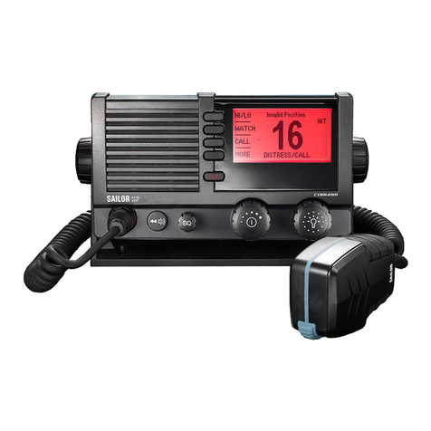
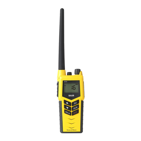
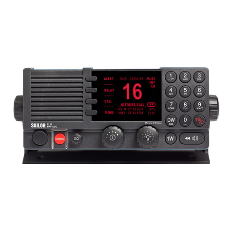
Sailor S6000 series User manual

SAILOR 6300B MF/HF Service Interface
User Manual
Document num er: 97-147768-A
Release Date: 31 August 2015

97-147768-A SAILOR 6300B MF/HF Serv ce Interface User Manual
2
Disclaimer
Any respons b l ty or l ab l ty for loss or damage n connect on w th the use of th s product and the accompany ng
documentat on s d scla med by Thrane & Thrane A/S. The nformat on n th s manual s prov ded for nformat on
purposes only, s subject to change w thout not ce and may conta n errors or naccurac es. Manuals ssued by
Thrane & Thrane A/S are per od cally rev sed and updated. Anyone rely ng on th s nformat on should acqu re the
most current vers on e.g. from http://www.cobham.com/commun cat ons-and-connect v ty/satcom, Serv ce and
support, or from the d str butor. Thrane & Thrane A/S s not respons ble for the content or accuracy of any
translat ons or reproduct ons, n whole or n part, of th s manual from any other source. In the event of any
d screpanc es, the Engl sh vers on shall be the govern ng text.
Thrane & Thrane A/S s trad ng as Cobham SATCOM.
Copyright
© 2015 Thrane & Thrane A/S. All r ghts reserved.
Record of revisions
Rev.
Descr pt on
Release Date
In t als
A
In t al
August 2015
JTR
A
Rev ew Comments from BLN, DAV, CMA, RSH,
JKR, TOP and JHO August 2015 JHO
A
Comments from CMA+TOP
August 2015
JHO

97-147768-A SAILOR 6300B MF/HF Serv ce Interface User Manual
3
Ta le of contents
1 Introduction .................................................................................................................... 4
1.1 Precaut ons us ng the serv ce tool ........................................................................................... 4
2 Connecting to the service tool ........................................................................................... 4
2.1 Connect ng to the serv ce w thout a network .......................................................................... 4
2.2 Connect ng to the serv ce tool through a network................................................................... 4
3 Overview of functionality ................................................................................................. 6
3.1 Open access funct onal ty ....................................................................................................... 6
3.1.1 STATUS .............................................................................................................................. 6
3.1.2 LOGS .................................................................................................................................. 8
3.1.3 NMEA ................................................................................................................................. 8
3.2 Protected access funct onal ty ................................................................................................ 9
3.2.1 CHANNELS ........................................................................................................................ 10
3.2.2 CONFIG .......................................................................................................................... 12
3.2.3 TOOLS ............................................................................................................................... 17

97-147768-A SAILOR 6300B MF/HF Serv ce Interface User Manual
4
1Introduction
The serv ce tool for the S6000 rad o ser es MF/HF dev ces s made ava lable by a bu lt- n
web server n the rad o. The serv ce tool can be accessed from a computer connected to a
LAN shared w th the dev ce and s d splayed n an nternet browser w th no add t onal
nstallat on of software requ red. Currently we do not guarantee full support for
M crosoft Internet Explorer, but most HTML5 enabled browsers are supported.
Screenshots n th s manual were done us ng Google Chrome.
1.1 Precautions using the service tool
WARNING: Wh le us ng the serv ce tool the network cable should not be removed
or d sconnected from ne ther the PC nor the rad o.
WARNING: Wh le us ng the serv ce tool, power to the rad o should not be sw tched off.
V olat on of the precaut ons above can result n a defect rad o, wh ch only
can be repa red by the manufacturer.
WARNING: The Serv ce agent s respons ble for all changes made w th the serv ce tool.
Changes must be n conformance w th rad o spec f cat ons and regulat ons.
2Connecting to the service tool
2.1 Connecting to the service without a network
The serv ce tool for the rad o can be accessed d rectly w thout use of a network, by use of
a PC w th automat c network conf gurat on and an nternet browser. Connect the rad o
to the computer us ng the Ethernet nterface and type the IP address of the rad o n the
address f eld of an nternet browser to access the serv ce tool. Th s w ll open the rad o
status page of the serv ce tool and the rad o can now be conf gured. The rad o’s current
IP address s v s ble n the SYSTEM SETUP menu on the rad o control un t or n the
rad o’s entry n the TMA tool as seen n Figure 1 below.
2.2 Connecting to the service tool through a network
The serv ce tool can be accessed through a LAN from a PC w th an nternet browser.
Type the IP address of the rad o n the address f eld of an nternet browser to access the
serv ce tool. Th s w ll open the rad o status page of the serv ce tool and the rad o can now
be conf gured. The rad o’s current IP address s v s ble n the SYSTEM SETUP menu on
the rad o control un t or n the rad o’s entry n the TMA tool as seen n Figure 1 below.
97-147768-A SAILOR 6300B MF/HF Serv ce Interface User Manual
5
Figure 1: TMA tool page for the radio displaying IP address, etc.

97-147768-A SAILOR 6300B MF/HF Serv ce Interface User Manual
6
3Overview of functionality
The serv ce tool s used to perform updates to the f rmware and var ous sett ngs of the
rad o. Th s sect on descr bes each feature of the serv ce tool n turn. The tool w ll show
nformat on about f rmware, status of the rad o and data from the logs for all users
w thout adm n strator r ghts, covered n sect on 3.1. For adm n strators the serv ce tool
prov des funct onal ty for conf gurat on of rad o sett ngs and tools for adm n strat on of
f rmware, covered n sect on 3.2.
3.1 Open access functionality
The open access nformat on of the serv ce tool s d v ded nto three tab pages, descr bed
n the follow ng three subsect ons.
3.1.1 STATUS
The STATUS tab page can be seen below n Figure 2.
Figure 2: Status ta .
The status tab s used to show the current platform and hardware conf gurat on of the
rad o. The f eld Hardware tracking ID s used n serv ce of the transce ver un t.

97-147768-A SAILOR 6300B MF/HF Serv ce Interface User Manual
7
If the ma n board of the rad o s replaced, a new ser al number can be appl ed n the
Current serial f eld. When no ser al number s programmed, the ‘current ser al’ f eld w ll
d splay a 10-d g t track ng number. Th s means that t s poss ble to nput the ser al
number of the system .
Note: updat ng the ser al number can only performed one t me and that updat ng the
f eld requ res logg ng n (descr bed n sect on 3.2).

97-147768-A SAILOR 6300B MF/HF Serv ce Interface User Manual
8
3.1.2 LOGS
The LOGS tab can be seen n Figure 3 below.
Figure 3: LOGS ta .
Th s tab ncludes four s de-bar buttons, where each d splays the respect ve logs over
Received Distress Calls, Received DSC Calls, Transmitted DSC Calls and one button for
the System Log. Each log can be downloaded as a .tar.gz f le.
3.1.3 NMEA
The NMEA tab pane d splays a stream of NMEA data collected over SERIAL and/or LAN.
The data can be downloaded as a compressed f le of the format .tar.gz and w ll conta n
more l nes than d splayed on the screen. See example pr ntout n Figure 4 below.
Figure 4: NMEA ta .
Note: Several tools are capa le of unpacking tar.gz files, including 7zip, Winrar,
Winzip, etc.

97-147768-A SAILOR 6300B MF/HF Serv ce Interface User Manual
9
3.2 Protected access functionality
Protected adm n strator access to the serv ce tool s obta ned by logg ng n us ng the
button n the upper r ght corner of the serv ce tool (see Figure 5 below).
Figure 5: Login utton.
By press ng the LOGIN button a pop-up w ll show.
Figure 6: Login pop-up.
To get adm n strator access enter the follow ng nto the two f elds:
•Username: admin
•Password: sailorsailor
When logged n to the protected part of the serv ce tool the rad o s d sabled and the tab
pages CHANNELS, CONFIG and TOOLS become access ble. These tabs are descr bed n
the follow ng sub sect ons.

97-147768-A SAILOR 6300B MF/HF Serv ce Interface User Manual
10
3.2.1 CHANNELS
An example of the CHANNELS tab can be seen n Figure 7 below.
Figure 7: CHANNELS ta .
Th s tab has a s de-bar button for var ous ITU channel bands and for pr vate channels.
The user must cl ck on a channel row on the page to select a channel for conf gurat on.
When select ng channel 241 the follow ng conf gurat on page for the channel appears
(Figure 8):

97-147768-A SAILOR 6300B MF/HF Serv ce Interface User Manual
11
Figure 8: Configuration of Channel 241.
Channel settings
Description
Allowed
?
Select th s tag to show the channel n the channel table and make t
ava lable v a the control un t.
Remove the tag to remove the channel from the channel table and
from the control un t. Th s can also be done for channels wh ch are
normally ncluded from the factory (ITU channels).
R
X
frequency
Spec fy rece ve frequency.
T
X
frequency
Spec fy transm ss on frequency.
T
X
Block
Select th s tag n order to block transm tt ng on th s channel.
Scan
Select th s tag to nclude th s
spec f c channel n the scann ng table.
Note that tagg ng all channels to be scanned w ll ncrease the t me
between scann ng each separate channel.
To conf gure the channel f ll n the respect ve f elds and cl ck the Su mit button.

97-147768-A SAILOR 6300B MF/HF Serv ce Interface User Manual
12
3.2.2 CONFIG
The CONFIG tab conta ns two s de-bar buttons and each are descr bed n turn:
Figure 9: CONFIG ta – Configuration side- ar page.
Configuration
Description
MMSI
Enter or change the MMSI number of the rad o.
Call ID or MMSI
Th s s the 5
-
d g t Telex call d. If
there s no 5
-
d g t call d
allocated you can use the 9-d g t MMSI or leave the f eld empty.
Abbrev ated ID
Th s s used for Telex dent f cat on and s part of the answer
back str ng. The abbrev ated ID s usually 4 ASCII letters, e.g.
‘abcd’.
Slave
delay
Th s s the slave
delay used dur ng Telex ARQ calls.
Default value
s 10.
ATU ava lable?
Des
elect th s tag f the system
does not have
an ATU (Antenna
Tun ng Un t) connected. The opt on s used for ded cated
antenna on spec f c frequency or dummy load.
Note: Wrong selection may damage the ATU.
PSU Mon tor
enabled
If the rad o’s power supply s a SAILOR 6081 you can enable the
Power Supply Mon tor n the rad o.
Pr mary
stat on
Select th s tag f you want th s rad o to have pr or ty over a
dupl cate MF/HF nstallat on.

97-147768-A SAILOR 6300B MF/HF Serv ce Interface User Manual
13
The MMSI, Call- d and abbrev ated ID are used to construct the telex answer back str ng.
The rule for creat ng a val d answerback str ng s:
•F gure sh ft
•Carr age return
•L ne feed
•9-d g t MMSI (or 5-d g t call ID)
•Letter sh ft
•Space
•Abbrev ated ID
•Space
•X
•Letter sh fts to br ng the total length up to 20 characters
The serv ce tool w ll automat cally add the f gure sh fts, letter sh fts, spaces and the letter
‘x’ where appropr ate. It s strongly recommended to check the telex sett ngs on the
SAILOR 6006 Message Term nal (Telex) when the sett ngs above have been mod f ed
and the rad o has been power cycled.

97-147768-A SAILOR 6300B MF/HF Serv ce Interface User Manual
14
Figure 10: CONFIG ta – Configuration side- ar page continued.
Options
Description
Enter code to enable telex
Enter the
opt on
code to enable telex.
After enter ng, the
opt on can be removed aga n by de-check ng the check box
D6 opt on
De
-
select
check box
to d sable D6
(6 channel watch keep ng
rece ver). To re-enable, nput the opt on code.
Low Power Mode Only
Transm t s only allowed at low output power.
External modem enabled
If the rad o s used n connect on w th external modem
,
enable th s opt on to ach eve correct power output.
Enable act ve antenna
Check th s opt on to enable s
upply current for act ve
antenna (12VDC max 60mA).
Scan hang t me
H
ang t me, n seconds
, to wa t on a channel w th s gnal,
before resum ng the scan.

97-147768-A SAILOR 6300B MF/HF Serv ce Interface User Manual
15
*) As for telex, the user must enter the code del vered w th the system to enable D6. The
f eld D6 opt on n F gure 10 above dep cts how the f eld appears when the act vat on code
has already been entered to the f eld. Before deselect ng opt ons, the serv ce tool ssues
a warn ng (see F gure 10, D6 opt on for example).
AUX Pin Settings:
Frequency [Hz]
Select the frequency for wh ch the AUX p n s act ve.
Mode
Choose between Off, Squelch open (as n
Figure 10
) or On
Channel.
Coast Station Mode:
Sw tch RX and TX freq?
Swaps duplex frequenc es
when used as a sh p counterpart.
Also GPS alarms and lead ng 00 n MMSI are allowed.
When all des red conf gurat ons are entered to the f elds, cl ck Su mit.

97-147768-A SAILOR 6300B MF/HF Serv ce Interface User Manual
16
Figure 11: CONFIG ta – Watch Keeping Receiver side- ar utton.
On the Watch Keeping Receiver page t s poss ble to program 6 DSC frequenc es nto
the watch rece ver or d sable frequenc es. These custom frequenc es w ll also be ava lable
for rout ne DSC transm ss ons. If the programmed frequenc es are requ red for a custom
d stress network (for d stress, safety and urgency calls), the follow ng opt on key s
requ red:
ABCD-1234-COBH-2014
WARNING: chang ng these frequenc es WILL alter the ab l ty to send and rece ve
d stress to/from establ shed GMDSS coast stat ons. Non-default programm ng of the
2MHz frequency also needs the spec al opt ons key as th s w ll vo d MF-DSC capab l ty.
WARNING: HF DSC funct onal ty requ res watch rece ver opt on, enabled scann ng on at
least 2MHz band, 8MHz band and at least one other band.
Cl ck Su mit when des red conf gurat on has been reached.

97-147768-A SAILOR 6300B MF/HF Serv ce Interface User Manual
17
3.2.3 TOOLS
Figure 12: TOOLS ta .
•The FW Update button lets the operator upload new f rmware to the rad o. Only
f les ssued by Cobham shall be used n the .t f format.
•The Factory Reset button can be used f the operator wants to return to the
default conf gurat on of the rad o. Th s means remov ng all sett ngs n the
channel tables, conf gurat ons, MMSI etc. Opt on codes for rad o telex and watch
keep ng rece ver w ll not be affected.
•Save Configuration downloads a .tar.gz f le w th all conf gurat ons done to the
rad o through the serv ce tool.
•Load Configuration s used to load conf gurat ons from a .tar.gz f le made
prev ously on the current rad o or another s m lar rad o.
3.3 Logout
Access the opt on menu n the upper r ght corner and choose to log out to do so. Upon
logg ng out, the rad o w ll reboot ut l z ng the new sett ngs and be ready for normal
operat on.
This manual suits for next models
1
Table of contents
Other Sailor Radio manuals

Sailor
Sailor RT2047 User manual

Sailor
Sailor 6248 VHF User manual

Sailor
Sailor RT2047 User manual

Sailor
Sailor R108 User manual

Sailor
Sailor SA-123 DAB+ User manual

Sailor
Sailor 6200 VHF Series User manual

Sailor
Sailor 6249 User manual

Sailor
Sailor 6210 VHF User manual

Sailor
Sailor SP3520 User manual

Sailor
Sailor SP3520 VHF GMDSS User manual