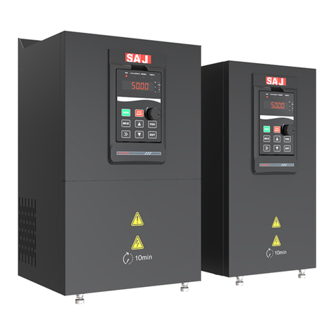
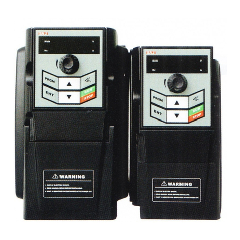
SAJ VM1000B User manual

VM1000B
- 0 -
VM1000B AC Drive
User Manual
Version Code: 6.0004.0391-00-VM1000B-E-V01-1908

VM1000B
- 1 -
Preface
Thank you for choosing VM1000B SeriesAC Drive.
This user manual introduces the technical specifications, installation
instructions,
functions and performance of VM1000B Series AC Drive properly.
Please read this
user manual carefully before carrying out works such as
installation,
commissioning, maintenance, etc.
You are specially warned to read and understand safety precaution items of
this manual before using this product, and to ensure that relevant electrical
installation testers’ professional qualification shall be in line with the provisions
of the labor supervision department, and the electrical and environmental
conditions
for product use shall be in conformity with relevant nationalstandards.
Be sure to verify that the wiring is correct before powering on the product.
Before starting the product, it is necessary to debug to ensure correct motor
rotating direction.
Please check for the latest version at www.saj-electric.com.
Guangzhou Sanjing Electric Co., Ltd.

VM1000B
- 2 -
Contents
PREFACE ......................................................................................................... - 1 -
SAFETY PRECAUTIONS .............................................................................. - 3 -
CHAPTER 1 PRODUCT INFORMATION................................................... - 6 -
1.1 TECHNICAL SPECIFICATIONS....................................................................................- 6-
1.2 PRODUCT NAMEPLATE .............................................................................................- 9-
1.3 MODEL DESCRIPTION...............................................................................................- 9-
1.4 PRODUCT MODEL...................................................................................................- 10 -
CHAPTER 2 INSTALLATION......................................................................- 11 -
2.1 OVERALL STRUCTURAL DRAWING(UNIT:MM)................................................- 11 -
2.2 KEYPAD STRUCTURAL DIMENSION DIAGRAM ........................................................- 13 -
2.3 MAIN CIRCUIT CONNECTION..................................................................................- 14 -
2.4 CONTROL CIRCUIT CONNECTION............................................................................- 15 -
CHAPTER 3 DISPLAYAND OPERATION................................................ - 19 -
3.1 KEYPAD .................................................................................................................- 19 -
3.2 DESCRIPTION OF INDICATORS AND KEYS ...............................................................- 20 -
CHAPTER 4 PARAMETER FUNCTION................................................... - 21 -
4.1 FUNCTIONAL PARAMETER......................................................................................- 21 -
4.2 FAULT RECORDS ....................................................................................................- 46 -
4.3 MONITORING PARAMETERS ...................................................................................- 47 -
CHAPTER 5 COMMUNICATION PROTOCOL....................................... - 49 -
5.1 COMMUNICATION CONTROLADDRESS...................................................................- 49 -
5.2 PARAMETER STATUS ADDRESS ...............................................................................- 50 -
5.3AC DRIVE STATE AND FAULT DESCRIPTION............................................................- 52 -
5.4 EEPROM-RAMADDRESS EXCHANGE DESCRIPTION............................................- 53 -
CHAPTER 6 TROUBLESHOOTING & COUNTERMEASURES........... - 54 -
6.1 FAULTS AND SOLUTIONS ........................................................................................- 54 -
6.2 COMMON FAULTS AND SOLUTIONS ........................................................................- 57 -
CHAPTER 7 CONTECT SAJ....................................................................... - 58 -
CHAPTER 8 WARRANTY POLICY........................................................... - 59 -
WARRANTY CARD...................................................................................... - 60 -

VM1000B
- 3 -
Safety precautions
■ Warning sign
DANGER: Indicates that failure to comply with the notice will result in
severe personal injure or even death.
WARNING: Indicates that failure to comply with the notice will result in
moderate personal injury, property damage or equipment damage.
WARNING
◎Do not install or operate any AC Drive that is damaged or with missing parts.
Failing to follow this rule can result in facility damage or severe injury.
◎When installing or handling the AC Drive, please hold the bottom of the
product rather than the case only, to prevent its falling and being damaged.
◎Install the AC Drive on nonflammable material like metal, and keep away from
flammable or explosive object, heat source, and similar environment. Otherwise,
fire may be caused.
◎When AC Drive is installed inside an electrical cabinet or other kind of
enclosure, please install fans or other cooling devices, and keep ventilation well
enough to ensure the enclosure temperature below 40℃, or the AC Drive may be
damaged due to extreme high temperature.
◎Before wiring, ensure the AC Drive rated input voltage and phases are
compatible with the input power source, or fire or personal injury may be caused.
◎Never connect the AC power supply to output terminals U, V and W.
Otherwise, the AC Drive will be damaged and the warranty is invalid.
◎Never carry out withstand voltage test to the AC Drive, for example by a
megohmmeter. Otherwise, it may cause damage to the AC Drive.
◎The connecting cable of the main circuit terminal should use an insulating
sleeve.
◎When the cable length between the AC Drive and the motor exceeds 50
meters, an output reactor is recommended to be used.

VM1000B
- 4 -
◎Do not use a circuit breaker to control the start and stop of the AC Drive.
Otherwise, the AC Drive may be damaged.
◎Since the AC Drive makes the motor running speed from low to high in a short
time, please confirm that the motor and equipment are in the allowed running
range before running.
◎Do not touch due to high temperature of the heat sink and braking resistor.
◎The factory parameters of the AC Drive can meet the requirments of most
equipment operation. Under normal circumstances, please do not modify the AC
Drive parameters at will. Even if there is some special applications need to change
the AC Drive parameters, only necessary parameters could be changed.
Otherwise, AC Drive damage may be caused.
◎The PCB board has a CMOS integrated circuit. Do not touch it with your hands,
otherwise, static electricity will damage the PCB board.
DANGER
◎Wiring must be completed by qualified professional electricians, otherwise,
there may be electric shock or damage to the AC Drive.
◎The power must be disconnected during wiring; otherwise, it may cause electric
shock or fire.
◎The grounding terminal should be effectively grounded; otherwise, the outer
casing of the AC Drive may be energized.
◎Do not touch the main circuit terminals, otherwise, it may cause electric shock.
◎Terminals for brake resistor are (+) and PB. Do not wire to other terminals,
otherwise, fire may be caused.
◎It is only allowed to power on the AC Drive after the wiring is finished and its
cover is reinstalled. It is strictly prohibited to remove the cover of AC Drive while
power is on. Otherwise, it may cause electric shock.
◎Before programming the AC Drive with fault auto reset or restart option after
power off, the mechanical device need to be implemented with safety protection
measures first. Otherwise, personal injury will be caused.

VM1000B
- 5 -
◎“ STOP/RESET” key may become invalid as a result of some function setting.
It is recommended to install an independent emergency circuit breaker for the
AC Drive control system, otherwise, or personal injury may be caused.
◎When the power is on, there may be electricity in the AC Drive’s terminals
even if it is in stop mode. Do not touch U, V, W terminals and motor connection
terminals, or electrical shock may be caused.
◎Never touch the AC Drive connection terminals when power is on. Otherwise,
it may cause an electrical shock.
◎Only qualified electricians can be authorized to do the jobs of maintenance,
checking, or parts replacement.
◎After the power supply is OFF, make sure the charge LED is OFF and the
residual voltage does not exist, or wait for at least 10 minutes before carrying out
maintenance or inspection. Otherwise, damage or injury may be caused.
◎Modification to the AC Drive without permission is strictly prohibited,
otherwise, severe injury may be caused. Arbitrarily modification of AC Drive
will result in service warranty invalid.

VM1000B
- 6 -
Chapter 1 Product information
1.1 Technical specifications
Item
Specifications
Control
features
Control mode
Sensorless vector control
(SVC)
V/F control
Startup torque
0.5Hz/150%
0.5Hz/100%
Speed range
1:100
1:50
Speed stability accuracy
±0.5%
±1%
Carrier frequency
0.5kHz ~16kHz; the carrier frequency is automatically
adjusted based on the load features.
Overload
capacity
G type: 60s for 150% of the rated current, 1s for 180% of the
rated current.
P type: 60s for 120% of the rated current, 1s for 150% of the
rated current.
Torque
boost
Fixed boost;
Customized boost 0.1% ~ 30.0%.
Input and
Output
Input voltage range
220V/380V; fluctuation range :±15%
Input frequency range
50/60Hz;fluctuation range :±5%
Output voltage range
0-input voltage; the error is less than 5%
Output frequency range
SVC:0-320Hz;V/F:0-1000Hz
Running
control
Running command source
Three command source:keypad; control terminals; serial
communication port.
You can perform switchover between these sources in various
ways.
Frequency source
There are 10 frequency sources in total, such as digital setting,
analog voltage setting, analog current setting, pulse setting and
serial communication port setting.
You can perform switchover between these sources in various
ways.
Auxiliary frequency
source
There are ten auxiliary frequency sources. It can implement
fine tuning of auxiliary frequency and frequency synthesis.
Input terminal
◆6 digital input terminals (DI),
◆2 analog input terminals (AI).

VM1000B
- 7 -
Item
Specifications
Output terminal
◆1 open-collector output terminal
◆2 relay output terminal.
◆2 analog output terminal .
Basic
function
DC braking
Braking time: 0.0s ~100.0s;
Braking action current value: 0.0% ~100.0%
V/F curve
Three modes: straight-line V/F curve, multi-point V/F curve,
square V/F curve.
Ramp mode
Straight-line ramp, S-curve ramp;
Four kinds of acceleration/deceleration time with the range of
0.0-6500.0s.
Simple PLC/Multiple
speeds
It implements up to 16 speeds via the simple PLC function or
combination of DI terminal states.
Built-in PID
It realizes process-controlled closed loop control system
easily.
AVR function
It can keep constant output voltage automatically when the
mains voltage changes.
Overvoltage/Overcurrent
stall control
The current and voltage are limited automatically during the
running process so as to avoid frequent tripping due to
overvoltage and overcurrent.
Rapid current limit
It helps to avoid frequent overcurrent faults of the AC Drive.
Torque limit and control
It can limit the torque automatically and prevent frequent over
current tripping during the running process.
Timing control
Timing control function: time range: 0h ~65535h
Protection mode
Motor short-circuit detection at power-on, input/output phase
loss protection, overcurrent protection, overvoltage
protection, undervoltage protection, overheat protection,
overload protection and so on.
Display and
Key
operation
LED display
It displays the parameters.
Parameters locking
function
It can lock the parameters to prevent malfunction.
MF.K key
Programmable key: command source switchover/ forward and
reverse running/ JOG running/menu mode switchover
Environme
nt
Installation location
Indoor, free from direct sunlight, dust, corrosive gas,
combustible gas, oil smoke, vapour, drip or salt.
Altitude
Lower than 1000m. When it is higher than 1000m, for every
100m, it needs to reduce power by 1%, and the maximum
altitude is 3000m.

VM1000B
- 8 -
Item
Specifications
Ambient temperature
-10℃~40℃. When it is higher than 40℃, for every 1℃, it
needs to reduce power by 1%, and the maximum ambient
temperature is 50℃
Humidity
≤95%RH, without condensing
Vibration
Less than 5.9m/s2 (0.6g)
Storage temperature
-25℃~+60℃
Table 1-1-1 Technical specification

VM1000B
- 9 -
1.2 Product nameplate
IP20
Product model
Power
Input specification
Product barcode
Certification /
Protection level
MODEL: VM1000B-4T18R5GB/022PB-E
POWER: 18.5kW/22kW
INPUT: 3PH AC 380V±15% 38.5/46A 50/60Hz
OUTPUT: 3PH AC 0-380V 37/45A 0-1000Hz
S/N:
Output specification
Guangzhou Sanjing Electric Co., Ltd.
manufacturers
Figure 1-2-1 Product nameplate
1.3 Model description
VM1000B –4 T 18R5GB / 022PB - E
①②③④⑤⑥
Field
No.
Identification
Description
Product series
①
Product series
VM1000B: general vector series
Voltagegrade
②
Voltagegrade
2: 220VAC;4: 380VAC
The input
power
③
Power phase
identification
S: single ;T: three-phase
Rated power 1
④
The power range of
G type
18R5-18.5kW,R is the decimal point
G—Constant torque load
B—Built-in brake unit
Rated power 2
⑤
The power range of
P type
022-22kW
P—Variable torque load
B—Built-in brake unit
Product model
suffix
⑥
Supported language
English
Table 1-3-1 VM1000B series model field comment

VM1000B
- 10 -
1.4 Product model
AC Drive Model
Rated
power
Power
capacity
Input current
Output
current
Motor G/P
kW
kVA
A
A
kW
HP
VM1000B-2SR75GB
0.75
1.5
8.2
4.5
0.75
1
VM1000B-2S1R5GB
1.5
3
14
7
1.5
2
VM1000B-2S2R2GB
2.2
4
23
9.6
2.2
3
VM1000B-4TR75GB
0.75
1.5
3.4
2.1
0.75
1
VM1000B-4T1R5GB
1.5
3
5.0
3.8
1.5
2
VM1000B-4T2R2GB
2.2
4
5.8
5.1
2.2
3
VM1000B-4T004GB/5R5PB
4/5.5
5.9/8.9
10.5/14.6
9/13
4/5.5
5.5/7.5
VM1000B-4T5R5GB/7R5PB
5.5/7.5
8.9/11
14.6/20.5
13/17
5.5/7.5
7.5/10
VM1000B-4T7R5GB
7.5
11
20.5
17
7.5
10
VM1000B-4T011GB/015PB
11/15
17/21
26/35
25/32
11/15
15/20
VM1000B-4T015GB/18R5PB
15/18.5
21/24
35/38.5
32/37
15/18.5
20/25
VM1000B-4T18R5GB/022PB
18.5/22
24/30
38.5/46
37/45
18.5/22
25/30
VM1000B-4T022GB/030PB
22/30
30/40
46.5/62
45/60
22/30
30/40
VM1000B-4T030G/037P
30/37
40/57
62/76
60/75
30/37
40/50
VM1000B-4T037G/045P
37/45
57/69
76/92
75/91
37/45
50/60
VM1000B-4T045G/055P
45/55
69/85
92/113
91/110
45/55
60/70
VM1000B-4T055G/075P
55/75
85/114
113/157
112/150
55/75
70/100
VM1000B-4T075G/093P
75/93
114/134
157/180
150/170
75/93
100/125
VM1000B-4T093G/110P
93/110
134/160
180/214
170/210
93/110
125/150
VM1000B-4T110G/132P
110/132
160/192
214/256
210/253
110/132
150/180
Table 1-4-1 Product model table

VM1000B
- 11 -
Chapter 2 Installation
2.1 Overall structural drawing(unit:mm)
Figure 2-1-1 0.75kW-7.5kW outline dimension diagram
AC Drive Model
Overall Dimensions
Mounting Hole
Mounting
Hole
Diameter
H
W
D
D1
H1
W1
d
VM1000B-2SR75GB
187
88
138
130
177
73
5
VM1000B-2S1R5GB
VM1000B-2S2R2GB
VM1000B-4TR75GB
VM1000B-4T1R5GB
VM1000B-4T2R2GB
VM1000B-4T004GB/5R5PB
207
100
147
139
197
85
5
VM1000B-4T5R5GB/7R5PB
247
130
167
159
237
113
5
VM1000B-4T7R5GB
Table 2-1-1 0.75kW-7.5kW outline dimension

VM1000B
- 12 -
Figure 2-1-2 11kW-110kW outline dimension diagram
AC Drive Model
Overall Dimensions
Mounting Hole
Mounting
Hole
Diameter
H
W
D
D1
H1
W1
d
VM1000B-4T011GB/015PB
348
182
211
196
331
156
6
VM1000B-4T015GB/18R5PB
VM1000B-4T18R5GB/022PB
373
220
205
190
356
156
6
VM1000B-4T022GB/030PB
VM1000B-4T030G/037P
435
256
222
208
419
170
6
VM1000B-4T037G/045P
VM1000B-4T045G/055P
543
310
280
265
523
245
10
VM1000B-4T055G/075P
VM1000B-4T075G/093P
580
358
328
314
560
270
10
VM1000B-4T093G/110P
VM1000B-4T110G/132P
Table 2-1-2 11kW-110kW outline dimension

VM1000B
- 13 -
2.2 Keypad structural dimension diagram
■Keypad size(Unit: mm)
Figure 2-2-1 0.75kW-7.5kW Keypad structure size
Figure 2-2-2 11kW-110kW Keypad structure size
■Keypad bracket (Unit:mm)
Power range
0.75kW-7.5kW
11kW-110kW
Hole size
69
98.5
85
121
Table 2-2-1 The keypad bracket mounting hole size

VM1000B
- 14 -
2.3 Main circuit connection
M
R/L
S
T/N
+PB -
U
V
W
PE
Braking resistor
MCCB MC
Power Input
terminal
L1
L2
L3
External component
Out terminal
Main circuit
PE
0.75kW-22kW
Figure 2-3-1 0.75kW-22kW main circuit wiring diagram
M
R
S
T
+P-
U
V
W
PE
DCreactor
MCCB MC
L1
L2
L3
Out terminal
PE
Braking resistor
Power Input
terminal
30kW-110kW
Main circuit
External component
Figure 2-3-2 30kW-110kW main circuit wiring diagram
Terminal
mark
Name
Description
R/L、S、T/N
Power supply input terminals
Connect to the AC power supply
(+)、(-)
Positive and negative terminals of
DC bus
Common DC busbar input terminal
Connect the external braking unit to the AC drive
of 30 kW and above Power Range
(+)、PB
Brake resistance
connecting
terminal.
Connect to the braking resistor for the AC drive of 22
kW and below Power Range
P、(+)
Connecting terminals of
external reactor
Connect to an external reactor.
U、V、W
AC drive output terminals
Connect the three-phasemotor.
Grounding terminal
Must be grounded.
Table 2-3-1 Main circuit terminals and function

VM1000B
- 15 -
2.4 Control circuit connection
0.75kW-7.5kW control terminal
24V(MAX 150mA)
+10V(MAX 20mA)
AI1(0-10V)
GND
COM
DI1
DI2
DI3
DI4
DI5
DI6
+24V
Forward
Reverse
Fault
reseting
Multi-speed
terminal 1
Multi-speed
terminal 2
Reserved
1~5kΩ
T1C
T1B
T1A
AO1
GND
+
-
AO1:0-10V/0-20mA
COM Digital output 1
RS+
RS-
AI2
(-)
(+)
(0-20mA/0-10V)
PE
RS485 communication
terminal
IAO1 V
J1
IAI2 V
J2
ON R 0FF
J5
R
Digital input terminal
Analog input
terminal
Communication terminal
Analog output
terminal
Digital output
terminal
FM
GNDPE
J3
COMPE
J4
Control circuit
NO
NC
Common terminal
Figure 2-4-1 0.75kW-7.5kW control terminal diagram

VM1000B
- 16 -
11kW-110kW control terminal
+
OP
24V(MAX 150mA)
+10V(MAX 20mA)
AI1(0-10V)
GND
COM
DI1
DI2
DI3
DI4
DI5
DI6
OP
Forward
Reverse
Fault
reseting
Multi-speed
terminal 1
Multi-speed
terminal 2
Reserved
1~5kΩ
T1C
T1B
T1A
AO1
GND
+
-
AO1:0-10V/0-20mA
CME
Digital output 1
NO
RS+
RS-
AI2
(-)
(+)
(0-20mA/0-10V)
PE
RS485 communication
terminal
IAO1 V
J1
IAI2 V
J2 ON R 0FF
J5
R
Digital input terminal
Analog input
Communication terminal
Digital output
terminal
Control circuit
T2C NO
T2A
FM
COM
AO2AO2:0-10V
GNDPE
J3
COMPE
J4
NC
Common terminal
Common terminal
Analog output
Figure 2-4-2 11kW-110kW control terminal diagram

VM1000B
- 17 -
Control terminal instruction
Category
Terminal
symbol
Terminal name
Function description
Power
supply
+10V-GND
+10V power supply
Provide +10V power supply to external unit.
Generally, it provides power supply to external potentiometer with
resistance range of 1-5 kΩ.
Maximum output current: 20 mA
+24V-COM
+24V power supply
Provide +24V power supply to external unit.
Generally, it provides power supply to DI/DO terminals and
external sensors.
OP
External power input
terminal
Connect to +24V by default.
When DI1-DI6 need to be driven by extemal signal, OP needs to
be connected to external power supply and be disconnected from
+24V.
Analog
input
AI1-GND
Analog input terminal 1
1. Input voltage range: 0-10V
2. Input resistance: 22 kΩ
AI2-GND
Analog input terminal 2
1. Input range: 0-10V/4-20mA, decided by jumper J8 on the
control board.
2. Input resistance: 22 kΩ(voltage input), 500Ω(current input)
Digital input
DI1
Digital input 1
1. Optical coupling isolation, compatible with dual polarity input
2. Input resistance: 3kΩ
3. Voltage range for level input: 9V -30V
DI2
Digital input 2
DI3
Digital input 3
DI4
Digital input 4
DI5
Digital input 5
DI6
Digital input 6
Analog
output
AO1-GND
Analog output 1
AO1: Voltage or current output is decided by jumper J5.
Output voltage range: 0-10V
Output current range: 0-20mA
AO2: Output voltage range: 0-10V
AO2-GND
Analog output 2
Digital
output
FM-CME
Digital output/high-
speed pulse output
open collector output
Output voltage range: 0V -24V
Output current range: 0mA - 50mA
Note that CME and COM are internally insulated, but they are
shorted by jumper externally. If you want to drive FM by external
power supply, Please remove the jumper.

VM1000B
- 18 -
Relay output
T1A-T1B
NO terminal
Contact driving capacity:
AC 250V,3A,COSø=0.4;
DC 30V,1A。
T1A-T1C
NC terminal
T2A-T2C
NO terminal
Communication port and
socket
RS+
RS485 signal positive terminal
RS-
RS485 signal negative terminal
Table 2-4-1 Control terminal instruction

VM1000B
- 19 -
Chapter 3 Display and operation
3.1 Keypad
You can modify the parameters, monitor the working status and start or stop the AC Drive by
operating the keypad, as shown in the following figure.
Figure 3-1-1 Keypad diagram
Table of contents
Other SAJ Controllers manuals
Popular Controllers manuals by other brands

Sentera
Sentera MTV-1/010-NA Mounting and operating instructions

Revolution Electronics
Revolution Electronics 12003 Installation instructions manual

GE
GE b30 Communications manual

Malossi
Malossi FORCE MASTER 2.1 Assembly instructions

OBL
OBL Z Series operating manual

GRAUPNER
GRAUPNER PS 5,9V operating manual