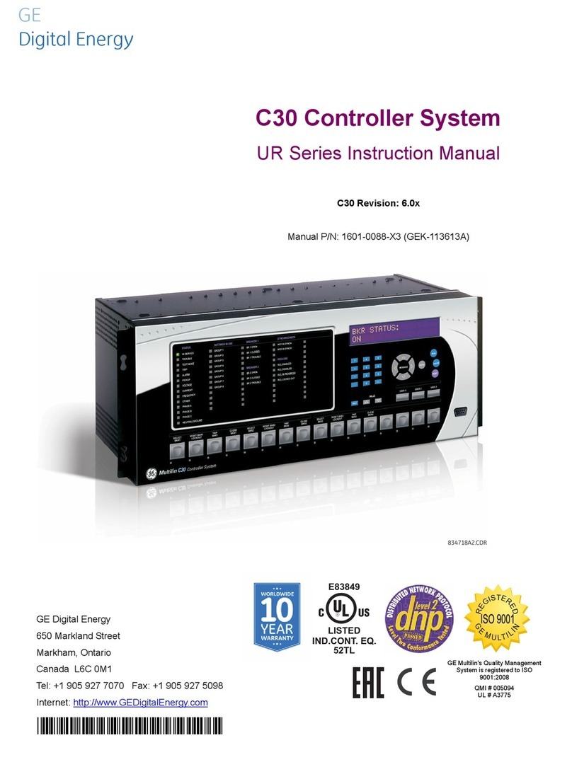
GE b30 Use and care manual

GE
Grid Solutions
Product version: 7.6x
GE publication code: 1601-0401-AF1 (GEK-131009)
UR Family
Communications Guide
1601-0401-AF1
IISO 9001
G
N
E
I
M
L
I
U
T
L
T
E
S
I
R
G
E
D
E
R
LISTED
IND.CONT. EQ.
E83849

Copyright © 2017 GE Multilin Inc. All rights reserved.
UR Family Communications Guide for version 7.6x.
UR Family, EnerVista, Multilin, and GE Multilin are trademarks or registered trademarks of
GE Multilin Inc.
The contents of this manual are the property of GE Multilin Inc. This documentation is
furnished on license and may not be reproduced in whole or in part without the permission
of GE Multilin. The content of this manual is for informational use only and is subject to
change without notice.
Part number: 1601-0401-AF1 (June 2017)

UR FAMILY – COMMUNICATIONS GUIDE iii
UR Family
Table of contents
1INTRODUCTION 1.1 Products................................................................................................................... 1-1
1.2 Features per product............................................................................................. 1-1
1.3 Communication ports ......................................................................................... 1-14
1.4 Safety symbols and definitions ......................................................................... 1-14
1.5 For further assistance......................................................................................... 1-14
2MODBUS
COMMUNICATION
2.1 Modbus RTU protocol ............................................................................................ 2-1
2.1.1 Introduction............................................................................................................................. 2-1
2.1.2 Configuration.......................................................................................................................... 2-1
2.1.3 Physical layer.......................................................................................................................... 2-1
2.1.4 Data link layer ........................................................................................................................ 2-2
2.1.5 Modbus RTU CRC-16 algorithm..................................................................................... 2-3
2.2 Modbus function codes......................................................................................... 2-4
2.2.1 Supported function codes................................................................................................ 2-4
2.2.2 Read actual values or settings (function code 03/04h)...................................... 2-4
2.2.3 Execute operation (function code 05h)...................................................................... 2-5
2.2.4 Store single setting (function code 06h) .................................................................... 2-5
2.2.5 Store multiple settings (function code 10h) ............................................................. 2-6
2.2.6 Exception responses........................................................................................................... 2-6
2.3 File transfers ........................................................................................................... 2-7
2.3.1 Obtaining relay files using Modbus.............................................................................. 2-7
2.4 Memory map ......................................................................................................... 2-12
2.4.1 Modbus memory map......................................................................................................2-12
2.4.2 Data formats .....................................................................................................................2-183
3 IEC 61850
COMMUNICATION
3.1 Overview.................................................................................................................. 3-1
3.1.1 Introduction............................................................................................................................. 3-1
3.1.2 Abstract Communication Service Interface (ASCI)................................................ 3-3
3.1.3 Datasets.................................................................................................................................... 3-6
3.1.4 TxGOOSE................................................................................................................................... 3-7
3.1.5 RxGOOSE .................................................................................................................................. 3-9
3.1.6 Reports ....................................................................................................................................3-10
3.1.7 Commands............................................................................................................................3-12
3.1.8 Substation Configuration Language (SCL)..............................................................3-12

iv UR FAMILY – COMMUNICATIONS GUIDE
TABLE OF CONTENTS
3.2 Configuring the UR using SCL.............................................................................3-18
3.2.1 Merge SCL file ......................................................................................................................3-23
3.2.2 Configurable logical devices.........................................................................................3-24
3.3 Protocol implementation conformance statement (PICS) ............................3-24
3.3.1 Basic conformance statement ....................................................................................3-24
3.4 ACSI conformance statement ............................................................................3-25
3.4.1 ACSI basic conformance statement .........................................................................3-25
3.4.2 ACSI models conformance statement.....................................................................3-25
3.4.3 ACSI services conformance statement ...................................................................3-27
3.5 Model implementation conformance statement (MICS)................................3-29
3.5.1 Master (root) logical device ........................................................................................... 3-30
3.5.2 Protection (Prot) logical device ....................................................................................3-37
3.5.3 Control (Ctrl) logical device ......................................................................................... 3-113
3.5.4 System logical device.................................................................................................... 3-147
3.5.5 Meter logical device.......................................................................................................3-168
3.5.6 General (Gen) logical device....................................................................................... 3-188
3.5.7 GE namespace ................................................................................................................. 3-204
3.5.8 Enumerations.................................................................................................................... 3-219
3.6 SCL implementation conformance statement (SICS) .................................. 3-220
3.7 PIXIT conformance statement......................................................................... 3-222
3.8 TICS conformance statement.......................................................................... 3-227
3.9 SCL logging ......................................................................................................... 3-229
3.9.1 Overview of process ...................................................................................................... 3-229
3.9.2 SCL file storage on UR................................................................................................... 3-230
3.9.3 Generation Of CID files ................................................................................................. 3-230
3.9.4 Schema version used by UR/EnerVista ................................................................ 3-230
3.9.5 CID file processing steps.............................................................................................. 3-230
3.9.6 SCL log file format and examples ........................................................................... 3-230
3.9.7 Troubleshooting log file errors.................................................................................. 3-232
3.10 G2 implementation model for GOOSE configuration via SCL.................... 3-232
3.10.1 Introduction ....................................................................................................................... 3-232
3.10.2 Configuration process .................................................................................................. 3-233
3.10.3 Configuration process with IED setup tool.......................................................... 3-235
3.10.4 IED Capability Description (ICD) file......................................................................... 3-235
3.10.5 Instantiated IED capability description (IID) file ................................................ 3-239
3.10.6 Configured IED description (CID) file....................................................................... 3-239
3.10.7 Sample SCL files............................................................................................................... 3-241
3.10.8 Annex - Optional intermediate GOOSE reception objects ........................... 3-246
3.11 E3-2.0 implementation model for GOOSE configuration via SCL ............. 3-249
3.11.1 Introduction ....................................................................................................................... 3-249
3.11.2 Workflow............................................................................................................................. 3-249
3.11.3 ICD files ................................................................................................................................ 3-250
3.11.4 CID files ................................................................................................................................ 3-251
3.11.5 IID files.................................................................................................................................. 3-252
4DNP
COMMUNICATION
4.1 Device profile document .......................................................................................4-1
4.1.1 Implementation table .........................................................................................................4-4
4.2 DNP point lists.......................................................................................................4-10
4.2.1 Binary input points ............................................................................................................ 4-10
4.2.2 Binary and control relay output..................................................................................4-10
4.2.3 Counters.................................................................................................................................4-12
4.2.4 Analog inputs.......................................................................................................................4-12

TABLE OF CONTENTS
UR FAMILY – COMMUNICATIONS GUIDE v
5 IEC 60870-5-103
COMMUNICATION
5.1 Overview.................................................................................................................. 5-1
5.2 Factor and offset calculation to transmit measurand.................................... 5-1
5.3 Interoperability document ................................................................................... 5-2
6 IEC 60870-5-104
COMMUNICATION
6.1 Interoperability document ................................................................................... 6-1
6.2 IEC 60870-5-104 points ....................................................................................... 6-10
A MISCELLANEOUS A.1 Revision history ......................................................................................................A-1
INDEX

vi UR FAMILY – COMMUNICATIONS GUIDE
TABLE OF CONTENTS

UR FAMILY – COMMUNICATIONS GUIDE 1-1
UR Family
Chapter 1: Introduction
Introduction
This document outlines the communications protocols for the Universal Relay (UR) family of products. It is intended for
customers who need detailed knowledge of the UR implementation of the communications protocols, for example to
design a client or to troubleshoot an interoperability issue. Use this guide with the appropriate Instruction Manual for the
product. Network and IP address configuration, passwords, and user roles, for example, are explained in the Instruction
Manual.
This chapter outlines general, safety, and technical support information.
1.1 Products
This document applies to the following UR products: B30, B90, C30, C60, C70, D30, D60, F35, F60, G30, G60, L30, L60, L90,
M60, N60, T35, T60.
The communications protocols that apply depend on those ordered. Check the order code of the device.
1.2 Features per product
The table outlines the theoretical maximum.
Features also can be viewed in the EnerVista software under Settings > Protection Summary.
Table 1-1: Maximum number of elements per product
Feature Rule Max B30 B90 C30 C60 C70 D30 D60 F35 F60 G30 G60 L30 L60 L90 M60 N60 T35 T60
Accidental
Energization
111

1-2 UR FAMILY – COMMUNICATIONS GUIDE
FEATURES PER PRODUCT CHAPTER 1: INTRODUCTION
1Automatic
Voltage
Regulator
# of
elements
if voltage
banks
present;0
if
Enhance
d
Capacitor
Bank
Control
software
option
not
ordered
33
Autoreclose # of
current
banks; 0
for L30
when
Three-
Pole
Auto-
Reclose
not
ordered
61641
Autoreclose
1P 3P
111 11
Auxiliary
Overvoltage
# of
elements;
1 per
voltage
bank and
3 if C70
has
voltage
banks
33 231232221122 3
Auxiliary
Undervoltage
#of
elements
if at least
one
voltage
bank
3 3 3333333333 3
B90 Breaker
Failure
# of
feeders
from
software
option
24 24
B90 Bus
Differential
# of
zones
from
software
option
66
Bus
configura
tion
66
Saturatio
n
detector
66
B90 IOC # of
current
terminals
24 24
B90 TOC # of
current
terminals
24 24
Feature Rule Max B30 B90 C30 C60 C70 D30 D60 F35 F60 G30 G60 L30 L60 L90 M60 N60 T35 T60

CHAPTER 1: INTRODUCTION FEATURES PER PRODUCT
UR FAMILY – COMMUNICATIONS GUIDE 1-3
1
B90
Undervoltage
# of
voltage
terminals
12 12
Basic UR
Features
Clock 1111111111111111111
Control
pushbutt
ons
7
Display
propertie
s
1
Default
message
s
1
LED test 1
Setting
file
template
1
Security 1
Trip and
Alarm
LEDs
1
Flex state
paramet
ers
256
User
program
mable
self-tests
1
Installatio
n
1
Voltage
rail
monitor
1
Temperat
ure
monitor
1
Breaker
Arcing
Current (I2t)
# of
current
banks; 2
if current
banks < 2
66 432264222242 66
Breaker
Control
# of
elements;
2 if
current
banks < 2
66 2432464222242666
(Disconnect)
Breaker
Switch
# of
elements
2424 8241281624168888248242424
Breaker
Failure
# of
elements;
2 if
current
banks < 2
66 43 4 4 22242 6
Breaker
Flashover
# of
elements;
2 if
current
banks < 2
22 21 222 2 222 2
Feature Rule Max B30 B90 C30 C60 C70 D30 D60 F35 F60 G30 G60 L30 L60 L90 M60 N60 T35 T60

1-4 UR FAMILY – COMMUNICATIONS GUIDE
FEATURES PER PRODUCT CHAPTER 1: INTRODUCTION
1Breaker
Restrike
# of
elements
33 33 233 2 222 3
Broken
Conductor
Detection
# of
sources
6 2262 222
Broken Rotor
Bar
1 1
Bus
Differential
22
Bus
configura
tion
2
Saturatio
n
detector
2
Bus Replica
Isolator
48 48
Capacitor
Bank
Overvoltage
# of
elements
33
Capacitor
Control
33
Change
Phase
Rotation
111
Charging
Current
Compensatio
n
11
Cold Load
Pickup
662
Compensated
Bank Neutral
Unbalance
# of
current
banks
33
Compensated
Overvoltage
1111
Cont. Monitor 1 1
Contact
Inputs
# of
inputs
120 120 120 120 120 120 120 120 120 120 120 120 120 120 120 120 120 120 120
Contact
Outputs
Latching
can be
only 14
72 72 72 72 72 72 72 72 72 72 72 72 72 72 72 72 72 72 72
CT Fail # of
current
banks
6 24 4442444666
CT Trouble # of
zones
from
software
option; 2
on B30
626
Current CT
settings
# of CT
banks
66 666666666666666
Current
Terminal
Metering
24 24
Current
Unbalance
2 2
DataLogger 11 1111111111111111
Feature Rule Max B30 B90 C30 C60 C70 D30 D60 F35 F60 G30 G60 L30 L60 L90 M60 N60 T35 T60

CHAPTER 1: INTRODUCTION FEATURES PER PRODUCT
UR FAMILY – COMMUNICATIONS GUIDE 1-5
1
Demand # of
sources
66 4 464 4 44 6 6
Digital
Counters
88 8888888888888888
Digital
Elements
48 48 48 48 48 48 48 48 48 48 48 48 48 48 48 48 48 48 48
Digitizer 5 5
Direct Inputs/
Outputs
16 inputs
and 8
outputs
111
Disturbance
Detection
# of
sources
66 462464442444666
Downed
Conductor
Detection (Hi-
Z)
Available
for 8Z
DSP only;
# of HIZ
records is
4; # of
RMS
records is
4
1
EGD Protocol Fast
productio
n = 1;
slow
productio
n = 2
11 11 1111 1 11
End of Fault
Protection
# of
elements;
1 per CT
terminal
24 24
Energy
Metering
# of
sources
66 4 46444 446 6
Event
Recorder
1024
events
1111111111111111111
Fault Location # of
elements;
1 per
current
bank
5 1 1152 111
Field Ground
Protection
11
Feature Rule Max B30 B90 C30 C60 C70 D30 D60 F35 F60 G30 G60 L30 L60 L90 M60 N60 T35 T60

1-6 UR FAMILY – COMMUNICATIONS GUIDE
FEATURES PER PRODUCT CHAPTER 1: INTRODUCTION
1Field
Resources
1 1111111111 11111
Field unit
brick
types
1
Field unit
contact
inputs
40
Field unit
contact
outputs
8
Field unit
CT/VT
settings
6
Field unit
I/O states
1
Field unit
latching
outputs
8
Field unit
raw data
actuals
8
Field unit
raw data
settings
1
Field unit
RTDs
8
Field unit
shared
inputs
16
Field unit
shared
outputs
16
Field unit
transduc
ers
8
Field
units
8
FlexElements 16 8 8 8 16 8 8 16 8 16 16 8 8 8 16 16 16 16
FlexLogic
Equations
1024
lines
111111111111111111
Flexlogic
timers
32
FlexMath 1
Direct
analogs
32 32
Direct
integers
16 16
Summato
r
6 6
Frequency
Rate of
Change
4 24 4442 4 4 4
Generator
Unbalance
111
Generic
Comparator
8-bit
comparat
or
6 6
Feature Rule Max B30 B90 C30 C60 C70 D30 D60 F35 F60 G30 G60 L30 L60 L90 M60 N60 T35 T60

CHAPTER 1: INTRODUCTION FEATURES PER PRODUCT
UR FAMILY – COMMUNICATIONS GUIDE 1-7
1
Ground
Distance
Fast
distance
is not
available
on L60
555355
Ground
Instantaneou
s Overcurrent
# of
elements
if at least
one CT
bank
126 1212121212121 1 12121212121212
Ground Time
Overcurrent
# of
elements
if at least
one CT
bank
66 666666116666666
IEC 61850
Communicati
ons
111111111111111111
Configur
able
GOOSE
Rx
16
Configur
able
GOOSE Tx
8
GGIO2
configura
tion
64
GGIO4
analog
points
32
GGIO5
unsigned
interger
points
16
MMXU
deadban
ds
6
Received
analogs
32
Received
integers
16
XCBR
configura
tion
6
XSWI
configura
tion
24
IPv4
Routes
6
Feature Rule Max B30 B90 C30 C60 C70 D30 D60 F35 F60 G30 G60 L30 L60 L90 M60 N60 T35 T60

1-8 UR FAMILY – COMMUNICATIONS GUIDE
FEATURES PER PRODUCT CHAPTER 1: INTRODUCTION
1IEC 61850
Remote I/O
(Fixed GOOSE/
GSSE/GOOSE)
11 111111111111 11
Remote
devices
32 16 16 32 16 16 16 16 16 16 16 16 16 16 16 16 16 16 16
Remote
DPS
inputs
5
Remote
inputs
64 32 32 64 32 32 32 32 32 32 32 32 32 32 32 32 32 32 32
Remote
output
DNA
pairs
32
Remote
output
UserSt
pairs
32
IEC 103
Communicati
ons
1111111111111111111
Incipient
Cable Fault
# of
elements
61621
L60 Channel
Tests
11
Line
Differential
(87L) In-Zone
Transformer
111
Line
Differential
(87L) L90
1 1
L90
Power
system
1
87L trip
logic
1
L90
phase
select
1
L90
channels
tests
1
Line
Differential
(87L)
No muti-
end fault
location
1
Line Pickup 1 1 1 1 1
Load
Encroachmen
t
1111111
Loss of
Excitation
111
Modbus
Communicati
ons
1111111111111111111
Modbus User
Map
1111111111111111111
Motor
Acceleration
Time
1 1
Motor
Mechanical
Jam
1 1
Feature Rule Max B30 B90 C30 C60 C70 D30 D60 F35 F60 G30 G60 L30 L60 L90 M60 N60 T35 T60

CHAPTER 1: INTRODUCTION FEATURES PER PRODUCT
UR FAMILY – COMMUNICATIONS GUIDE 1-9
1
Motor Start
Supervision
1 1
Negative
Sequence
Directional OC
# of
elements
if at least
one CT
bank and
one VT
bank
3222222223
Negative
Sequence
Instantaneou
s Overcurrent
# of
elements
if at least
one CT
bank
3 22222 222 3
Negative
Sequence
Overvoltage
C70
# of
voltage
banks if
at least
one
33
Negative
Sequence
Overvoltage
# of
elements
if at least
one
voltage
bank
3 33 33333 3 3
Negative
Sequence
Time
Overcurrent
# of
elements
if at least
one CT
bank
3 22222 222 3
Neutral
Current
Unbalance
# of
current
banks
33
Neutral
Directional
Overcurrent
3 122 22222223 3
Neutral
Instantaneou
s Overcurrent
# of CT
banks if
at least
one
66 11
Neutral
Instantaneou
s Overcurrent
# of
elements
if at least
one CT
bank
12 12 12 12 12 12 12 12 12 12 12 12 12
Neutral
Overvoltage
# of
elements
if at least
one VT
bank
33 333333333333 3
Neutral Time
Overcurrent
# of
elements
if at least
one CT
bank
66 6666662266666 6
Neutral
Voltage
Unbalance
# of
voltage
banks
33
Non Volatile
Latches
16 16 16 16 16 16 16 16 16 16 16 16 16 16 16 16 16 16 16
Open Pole
Detect
(supervisory)
1 1
Feature Rule Max B30 B90 C30 C60 C70 D30 D60 F35 F60 G30 G60 L30 L60 L90 M60 N60 T35 T60

1-10 UR FAMILY – COMMUNICATIONS GUIDE
FEATURES PER PRODUCT CHAPTER 1: INTRODUCTION
1Oscillography 1 111111111111111111
Over Under
Frequency
Accumulation
Frequenc
y out of
band
111
Overfrequenc
y
4 4 4444 4444
Phase
Comparison
11
Phase Current
Unbalance
# of
current
banks
33
Phase
Directional
# of
elements
if at least
one CT
and one
VT bank
32 222 21122223 3
Phase
Distance
L60 does
not
support
fast
distance
(L60 must
become
fast
distance)
5553355
Phase
Instantaneou
s Overcurrent
# of
elements
if at least
one CT
bank
12 12 12 12 12 12 12 12 12 12 12 12 12 12 12 12 12
Phase
Overvoltage
# of
elements
if at least
one VT
bank
33 3333333333333 3
Phase Time
Overcurrent
# of
elements
if at least
one CT
bank
66 666666666666666
Phase
Undervoltage
# of
elements
if at least
one VT
bank
33 3333333333333 3
PID Regulator 4 4 4
Feature Rule Max B30 B90 C30 C60 C70 D30 D60 F35 F60 G30 G60 L30 L60 L90 M60 N60 T35 T60

CHAPTER 1: INTRODUCTION FEATURES PER PRODUCT
UR FAMILY – COMMUNICATIONS GUIDE 1-11
1
Pilot Schemes 1
Pilot
blocking
(1P)
Pilot
blocking
1 (1P)
11
Pilot
DCUB
11
Pilot
DUTT (1P)
11
Pilot
Hybrid
POTT (1P)
11
Pilot
POTT (1P)
11
Pilot
POTT1
(1P)
11
Pilot
PUTT (1P)
11
Pilot
POTT
1
Pilot
POTT3
1
Pilot
blocking
3 (DCB3)
1
Platform
Direct I/O
256 32 256 64 32 32 32 32 32 32 32 32 32 32 64 32 32
Power Swing
Detect
11111111
Precision
Time Protocol
(1588)
3333333333333333333
Reduced
Voltage
Starting
1 1
Restricted
Ground Fault
# of
elements;
0 if L90
has no
inzone
transfor
mer
6444466
RRTD
Protection
12 12 12 12
RTD
Protection
48 48 48 48
Security 1111111111111111111
Selector
Switch
22 2222222222222222
Sensitive
Directional
Power
# of
elements
if at least
one VT
bank
2222222222
Setting
Groups
666 666666666666666
Feature Rule Max B30 B90 C30 C60 C70 D30 D60 F35 F60 G30 G60 L30 L60 L90 M60 N60 T35 T60

1-12 UR FAMILY – COMMUNICATIONS GUIDE
FEATURES PER PRODUCT CHAPTER 1: INTRODUCTION
1Simple
Network Time
Protocol
1111111111111111111
Single Pole
Tripping
111 11
Open
pole
detect
(1P)
Phase
selection
Trip
output
Sources (1 per
CT/VT bank)
# of
sources
66 462464442444666
Split Phase
Protection
111
Stator
Differential
111
Saturatio
n
detector
1
Stator Ground 1 1 1
Stub Bus 1 1 1
Subharmonic
Stator Ground
11
Switch 6 6 6 6
Synchrocheck 10 10 410 4444410 6 6
Synchrophas
ors
# of
PMUs;
software
option
621111161
# of
Aggregat
ors
421111141
Teleprotectio
n I/O
11 111111111 1 1111
Thermal
Model
1 1
Motor
setup
1
Thermal
Overload
Protection
22 22222222222 222
Third
Harmonic
Neutral
Undervoltage
111
Time of Day
Timer
55
Transducer I/
O
1 1111111111111111
DCMA
inputs
24
DCMA
outputs
24
Ohm
inputs
2
RTD
inputs
48
Feature Rule Max B30 B90 C30 C60 C70 D30 D60 F35 F60 G30 G60 L30 L60 L90 M60 N60 T35 T60

CHAPTER 1: INTRODUCTION FEATURES PER PRODUCT
UR FAMILY – COMMUNICATIONS GUIDE 1-13
1
Transformer
Instantaneou
s Differential
111
Transformer
Percent
Differential
1111
Transformer
windings
6266
Transformer
Thermal
Model
1111
TripBus 6666666666666666666
Undercurrent 1 1
Underfrequen
cy
6 6666666 66666
UnderPower 2 2
User-
Programmabl
e Fault Report
222 2 22 2222
User-
Programmabl
e LEDs
48 48 48 48 48 48 48 48 48 48 48 48 48 48 48 48 48 48 48
User-
Programmabl
e
Pushbuttons
# of
pushbutt
ons; 16; 6
for
vertical
front
panel
111111111111111111
control
push-
buttons
3333333333333333333
User-
Definable
Displays
16 16 16 16 16 16 16 16 16 16 16 16 16 16 16 16 16 16 16
Virtual Inputs 64 64 64 64 64 64 64 64 64 64 64 64 64 64 64 64 64 64 64
Virtual
Outputs
96 96 96 96 96 96 96 96 96 96 96 96 96 96 96 96 96 96 96
Voltage
Differential
# of VT
banks
33
Volts Per
Hertz
# of
elements
if at least
one VT
bank
22222
VT Fuse
Failure
# of
sources if
CT bank
or VT
bank
6 4624644422446 6
Wattmetric
Ground Fault
# of
elements
4 2242 22
Feature Rule Max B30 B90 C30 C60 C70 D30 D60 F35 F60 G30 G60 L30 L60 L90 M60 N60 T35 T60

1-14 UR FAMILY – COMMUNICATIONS GUIDE
COMMUNICATION PORTS CHAPTER 1: INTRODUCTION
11.3 Communication ports
URs are equipped with a front RS232 port, a rear RS485 port, an IRIG-B input port, and three Ethernet ports. The Ethernet
ports are a combination of 100Base-TX and 100Base-FX depending on the order code option. See the relevant Instruction
Manual for information on these ports.
1.4 Safety symbols and definitions
Before attempting to install or use the device, review all safety indicators in this document to help prevent injury,
equipment damage, or downtime.
The following safety and equipment symbols are used in this document.
See the Instruction Manual for safety information.
1.5 For further assistance
For product support, contact the information and call center as follows:
GE Grid Solutions
650 Markland Street
Markham, Ontario
Canada L6C 0M1
Worldwide telephone: +1 905 927 7070
Europe/Middle East/Africa telephone: +34 94 485 88 54
North America toll-free: 1 800 547 8629
Fax: +1 905 927 5098
Website: http://www.gegridsolutions.com/multilin
Indicates a hazardous situation which, if not avoided, will result in death or serious injury.
Indicates a hazardous situation which, if not avoided, could result in death or serious injury.
Indicates a hazardous situation which, if not avoided, could result in minor or moderate injury.
Indicates practices not related to personal injury.
Other manuals for b30
8
This manual suits for next models
36
Table of contents
Other GE Controllers manuals

GE
GE AF-650 GP Series User manual

GE
GE Becker VRP-B-CH Series User manual

GE
GE PACSystems* RX3i User manual

GE
GE Logix 764 User manual

GE
GE D.20 RIO Instructions for use

GE
GE VAT20 User manual

GE
GE IC3645SR4U454Z2 User manual

GE
GE AF-60 LP User manual

GE
GE ASTAT XT QT 0008U Series User manual

GE
GE 90-30 PLC Assembly Instructions

GE
GE GEK-113045B User manual

GE
GE iBox Product manual

GE
GE EV100 LX User manual

GE
GE Masoneilan 12400 Series User manual

GE
GE IC3645SR7A353E1 User manual

GE
GE PACSystems RX3i IC695ACC403 User manual

GE
GE VR-1 Owner's manual

GE
GE MOTOR MANAGER 2 User manual

GE
GE Masoneilan SVi 1000 User manual

GE
GE ASTAT XL User manual