Salcom 12-62-0000 User manual

Copyright © 2017 Sea Air and Land Communications Ltd. All rights reserved.
12-62-0000
VHF / UHF Transmitter
PRODUCT MANUAL
Version 1.02
January 2018

P a g e | 1
12-62-0000 VHF & UHF TRANSMITTER
Product Manual
Sea Air and land Communications Ltd, 10 Vanadium Place, Addington, Christchurch 8024, New Zealand January 2018
Salcom Product Documentation
This document is designed to familiarise you with Salcom products and guide you through the
hardware, configuration, installation and overall system management.
Salcom is an environmentally conscious company and in an effort to conserve paper no longer
prints manuals with shipped products. All relevant documentation can be downloaded in PDF
form from our website www.salcom.com

P a g e | 2
12-62-0000 VHF & UHF TRANSMITTER
Product Manual
Sea Air and land Communications Ltd, 10 Vanadium Place, Addington, Christchurch 8024, New Zealand January 2018
Warranty and Disclaimer
Salcom products are warranted for a period of 12 months from the date of purchase against faulty
materials and workmanship. Should any fault occur the unit should be returned to the vendor,
freight pre-paid. Please include a description of the fault to assist with prompt return. Any
unauthorised alterations or repairs will invalidate the warranty.
All information provided in this document is carefully prepared and offered in good faith as a
guide in the installation, use and servicing of Salcom products. Installers must ensure that the final
installation operates satisfactorily within the relevant regulatory requirements. Salcom accept no
responsibility for incorrect installation. We reserve the right to change products, specifications and
installation data at any time without notice

P a g e | 3
12-62-0000 VHF & UHF TRANSMITTER
Product Manual
Sea Air and land Communications Ltd, 10 Vanadium Place, Addington, Christchurch 8024, New Zealand January 2018
Contents
Warranty and Disclaimer..................................................................................................................................... 2
Product Overview................................................................................................................................................. 4
Product Features - Overview .............................................................................................................................. 5
Connectors and PinOuts ..................................................................................................................................... 6
Physical Description.............................................................................................................................................. 7
Installation.............................................................................................................................................................. 8
Programming ........................................................................................................................................................ 9
Using Serial Commands to Program your 12-62 ............................................................................................. 20
Product Feature - Messaging............................................................................................................................ 36
Product Feature –Store & forward .................................................................................................................. 38
Product Feature –Low Power Mode ............................................................................................................... 39
Product Feature –Duplicate Message Reject ............................................................................................... 40
Product Feature –Simulcast Modulation Delay............................................................................................. 41
Product Feature –Over Temperature Cutout ................................................................................................ 43
Product Feature –Aerial Mismatch ................................................................................................................. 44
Guidelines –Assignment of RIC Codes ........................................................................................................... 46
Guidelines - Antenna Selection and Installation............................................................................................ 48
System Solutions .................................................................................................................................................. 49
Protocols –Overview.......................................................................................................................................... 52
Trouble Shooting ................................................................................................................................................. 55
Glossary................................................................................................................................................................ 56
Accessories and Related Products.................................................................................................................. 57
Technical Specification ..................................................................................................................................... 58
How to Contact Us ............................................................................................................................................. 60

P a g e | 4
12-62-0000 VHF & UHF TRANSMITTER
Product Manual
Sea Air and land Communications Ltd, 10 Vanadium Place, Addington, Christchurch 8024, New Zealand January 2018
Product Overview
The 12-62 Series transmitters are available as VHF and UHF units, with user-programmable power
outputs ranging from 50 milliwatts to 4 watts and a high VSWR tolerance. Using programming
software, each model can be tuned across its full frequency range with no hardware adjustments.
They are capable of operating as NRZ or POCSAG transmitters. The built-in POCSAG encoder can
be enabled or disabled as required.
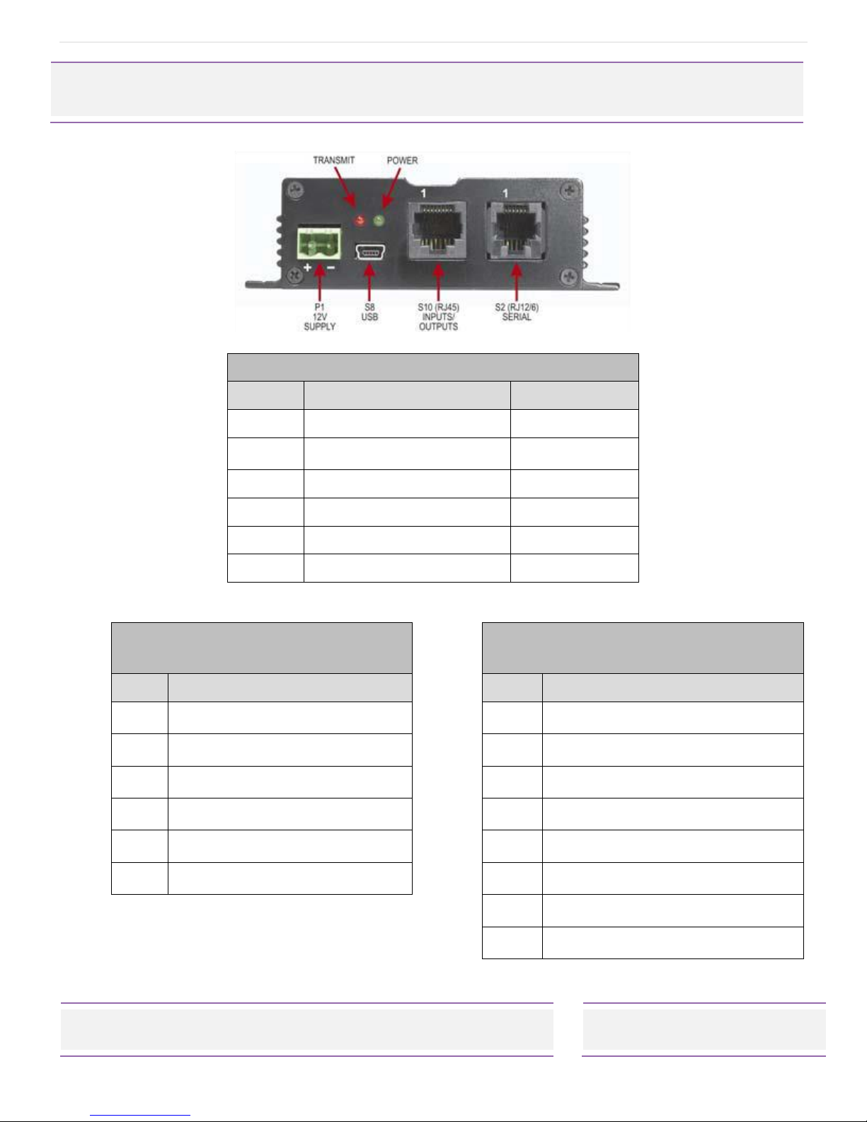
In addition to a direct/RS232 buffered serial port, an on-board USB port enhances the range of
applications to which the transmitter can be applied. Input / Output expansion is also possible via
an external RJ45 interface
The USB, RS232 ports can be used to initiate paging transmissions using the Salcom proprietary
protocol, or Telocator Alphanumeric Protocol (TAP) PG1 PET (Paging Entry Protocol). These ports
can be used concurrently making it possible to connect a telephone interface unit and still initiate
paging transmissions via the USB port, with the RF output being through a standard BNC
termination.
The unit supports 4 discrete inputs with a different pre-programmed message on high and/or low
transition, plus voltage detection messages on the power input, having programmable debounce
delay control. They may be used to initiate relay commands for remote control applications.
Provision to transmit a message more than once and variable time between transmissions are
catered for.
The 12-62 supports multiple message queuing, and will queue up to eight 240 character messages,
or as many smaller messages that will fit into the available memory buffer (up to 80). Pre-defined
input messages are limited to a maximum length of 40 characters which may be configured using
the Salcom programming software. Control via the USB or Serial port is achieved using ASCII
character commands.
A watchdog is available to initiate an action or transmit the state of selected inputs at a
programmable frequency.
The 12-62 can be configured to transmit a warning message when the power supply (battery)
goes below a user specified minimum level and above a user specified maximum level.
Configuration of the transmitter is performed via the USB port or the serial port using the Salcom
programming application which allows for the setting of all operational parameters.
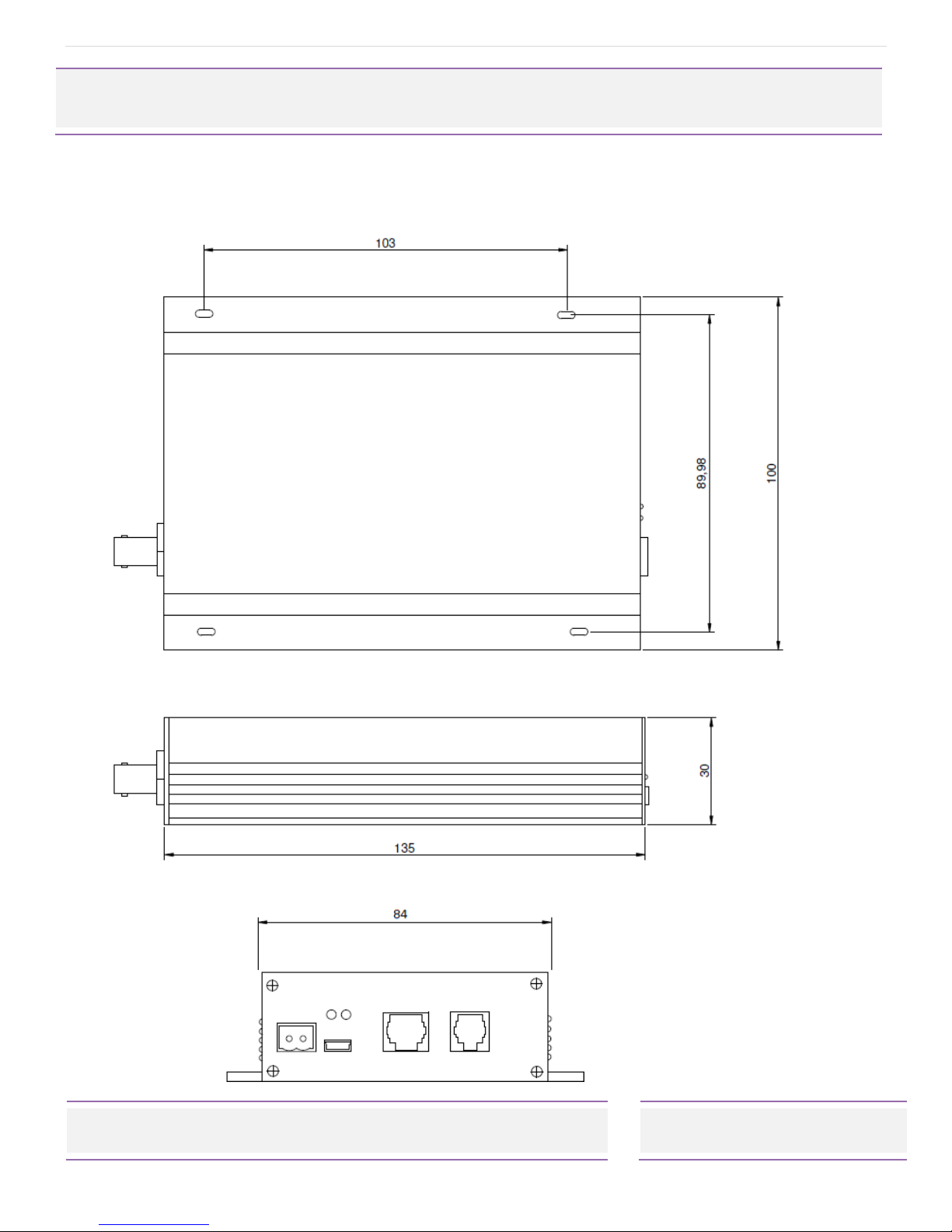
The 12-62 is housed in an attractive, durable extruded aluminium case with provision on the base
plate for wall mounting.

P a g e | 5
12-62-0000 VHF & UHF TRANSMITTER
Product Manual
Sea Air and land Communications Ltd, 10 Vanadium Place, Addington, Christchurch 8024, New Zealand January 2018
Product Features - Overview
The 12-62 comes with several features that make the 12-62 a versatile solution to your
communication needs. Key features are overviewed below, with more details of their use provided
later in this manual.
•Messaging: The 12-62 supports pager messaging and can transmit 3 types of POCSAG
message (alphanumeric transmissions, numeric transmissions and tone only transmissions),
with any one of 4 function levels.
•Store & forward: Can be configured to operate as a store & forward transmitter. This is when
a transmitter is designated as a source, and a receiver listens to the source relaying the
message to another transmitter for retransmission. Configurable as an optional feature.
•Low Power Mode: In Low Power Mode the 12-62 will consume approximately 17.5mA until
the interrupt line INT4 goes low which will wake the 12-62 up into its normal standby state
consuming 35mA.
•Duplicate Message Reject: when enabled a database of the last 20 messages sent is
maintained. All of the entries are progressively aged out. The age out time of entries in the
list can be set from 1-255 seconds. Configurable as an optional feature.
•Simulcast Modulation Delay: when enabled, allows the user to configure the transmission
delay for modulated data. This delay can be configured to be between 10uS and 2550uS.
•Over Temperature Cutout: If the transmitter operates for extended periods in a hot
environment, a protective thermal cutout may operate to reduce the output power to a
safe level. It will reset when the unit temperature has fallen to below 70 deg.
•Aerial Mismatch: when enabled, allows reporting when an aerial is disconnected or
damaged. If a problem is encountered along with error reporting the power is reduced to a
level that is not likely to damage the transmitter. The feature must be self-calibrated for
each installation before use.

P a g e | 6
12-62-0000 VHF & UHF TRANSMITTER
Product Manual
Sea Air and land Communications Ltd, 10 Vanadium Place, Addington, Christchurch 8024, New Zealand January 2018
Connectors and PinOuts
Table 1: Connectors and Indications
Item
Description
Designation
1
12V Supply
P1
2
USB
S8
3
Inputs/Outputs (RJ45)
S10
4
Serial (RJ12/6)
S2
5
Transmit LED (Red)
L1
6
Power LED (Green)
L2
Table 2: Pin connections for S2
(RJ12/6 Serial) connector
Table 3: Pin connections for S10 (RJ45
Inputs/Outputs) connector
Pi
n
Connection
Pin
Connection
1
Ground
1
PTT OUT, 50mA max
2
Interrupt
2
Ground
3
SCL
3
Discrete Input 4
4
SDA
4
Discrete Input 3
5
RS232 Tx
5
Discrete Input 2
6
RS232 Rx
6
Discrete Input 1
7
PTT Input for NRZ operation
8
Modulation Input for NRZ
operation

P a g e | 7
12-62-0000 VHF & UHF TRANSMITTER
Product Manual
Sea Air and land Communications Ltd, 10 Vanadium Place, Addington, Christchurch 8024, New Zealand January 2018
Physical Description
The 12-62 is installed in an extruded aluminum case with chassis holes for easy mounting. The
following figure shows the dimensions of the 12-62 chassis and mounting holes.

P a g e | 8
12-62-0000 VHF & UHF TRANSMITTER
Product Manual
Sea Air and land Communications Ltd, 10 Vanadium Place, Addington, Christchurch 8024, New Zealand January 2018
Installation
Power Supply
The power supply is connected via PI, green power connector to +13.8 Volts DC and Ground. The
unit is protected against reversed supply connections. The power source must be reasonably noise
free.
Radiation Hazard: Important! To comply with FCC Controlled/Occupational Exposure Limits the
aerial must be positioned or mounted to operate at least 0.26 metres away from Operational Staff
and 0.57 metres away from the general public. Use only the aerial supplied.
Antenna Installation
It is recommended to site the aerial a few metres away from the unit to avoid the possibility of RF
feedback and causing potential problems with the transmitter operation. An external (outside)
aerial is preferable and will provide better radio coverage. A suitable antenna must be connected
to the unit via the BNC connector on the end plate of the unit. The aerial connection should
present a nominal load of 50Ω, with a VSWR of better that 1.8:1.
The Salcom unit is designed to operate reliably over large distances, however the actual distance
can vary depending on the type of location, obstructions, local radio interference and antenna
system used.
Powering-Up
External indicators consist of a power indicator GREEN LED, normally flashing ON once per second
to indicate healthy microcontroller operation.
After a debounce delay, the green LED will flash rapidly if the low supply detector is activated. The
RED LED will indicate when the unit is transmitting. A flashing RED LED indicates the unit cannot
transmit as either the synthesiser is out of lock, the 12-62 is critically hot or an internal fault has been
detected.

P a g e | 9
12-62-0000 VHF & UHF TRANSMITTER
Product Manual
Sea Air and land Communications Ltd, 10 Vanadium Place, Addington, Christchurch 8024, New Zealand January 2018
Programming
Preparing to Use the Programming Software
To change the field programmable options, the unit must be connected to a PC using Windows XP
or later, running the 12-62 PSD programming software, downloadable from Salcom’s website
http://www.salcom.com/media/software/Salcom-1262-PSD-v2109.msi
Note: The 12-62 must be powered during programming with a nominal +13.8V to the power
terminals.
Connection should be via either the
(preferred) USB port S8, using the supplied
USB to USB mini cable, or the standard
serial port S2 to a serial port on the PC i.e.
DB9 connector.
When connected to your PC using the
USB to USB mini cable a (virtual) com port
will be created for that connection on
your PC.
Note: To use the USB connector with older computers, a virtual COM port USB driver may be
required to be installed. To install the USB driver (CP210x_VCP_Win2K_XP_S2K3.exe), run the driver
installer, which can be downloaded for your operating system, from Silicon Laboratories:
https://www.silabs.com/products/development-tools/software/usb-to-uart-bridge-vcp-drivers
Note: If you do not have a serial cable you can make one with the S2 connections as shown in the
section Connectors and Pin-outs in this document. Alternatively purchase a Salcom serial
programming cable, part number 12-45-0000.
Note: Using the standard serial port S2 with a serial to USB cable will not work due to the high
speed of the USB port in relation to the serial S2 connection of the 12-62.

P a g e | 10
12-62-0000 VHF & UHF TRANSMITTER
Product Manual
Sea Air and land Communications Ltd, 10 Vanadium Place, Addington, Christchurch 8024, New Zealand January 2018
Getting started with the Programming
Software
Once correctly connected, load the 12-
62 PSD programming software, this
should bring up a screen as shown
opposite:
This is the main screen from where you
can change the settings of your 12-62,
but before you can change any settings
you need to connect your PC to your 12-
62.
To connect your PC to your 12-62 select
Options and then General this will load
the General Settings screen, as below
Click on the Com Port dialog arrow to
select the Com Port your 12-62 is
connected to.
Note: Ensure that the 12-62 PSD has the
correct com port selected.
Next select “OK”to return to the above
screen. Press connect. The status at the
bottom of the 12-62 PSD will indicate if
successfully connected.
To get a valid set of parameters to start
your programming configuration, either
press the read button. This will load all
settings of the 12-62.
Or alternatively load a PSD configuration
file, by selecting the “File->Load”menu
item and browsing and selecting a saved
configuration.

P a g e | 11
12-62-0000 VHF & UHF TRANSMITTER
Product Manual
Sea Air and land Communications Ltd, 10 Vanadium Place, Addington, Christchurch 8024, New Zealand January 2018
Note: One of these actions is recommended before any changes can be programmed to ensure
the unit is not programmed with the PSDs default values.
After programming the PSD will provide feedback if the user selected operations are successful.
Using the Programming Software
The 12-62 PSD allows the user to configure the following characteristics:
•Input actions, watchdog, low supply detector and POCSAG transmission settings
•Pre-defined messages
•RF frequency and output power
•99 pager numbers for use with the Salcom 12-36 telephone interface.
Use the mouse to select the configuration fields for each feature, which you want to change and
then select ‘Program’ to update your 12-62’s configuration.
Note: After programming the 12-62 you must select “Disconnect” for the changes to take affect
and for the 12-62 to return to its normal operational state.
PSD Input Configuration
Low / High Input: Define the action that is
to occur when either a low or high input is
activated.
Input: All inputs may be configured in a
similar fashion, including supply voltage
monitoring. The input drop down box
provides support for the 4 inputs (Settings
“1”to “4”), available on connector S10,
and the “Battery”.
Each input can have a message defined
for both its high and low state. With the
input parameters being configured as
shown below:
The “Battery”input is used for setting a
minimum and maximum battery voltage
warning. See later under “Min Batt v”and
”Max Batt v”for configuration.

P a g e | 12
12-62-0000 VHF & UHF TRANSMITTER
Product Manual
Sea Air and land Communications Ltd, 10 Vanadium Place, Addington, Christchurch 8024, New Zealand January 2018
Pager type: “Alpha Numeric” or “Numeric”. Tone only pagers are supported by ensuring that the
message field is left blank.
Beep Level: Page beep level having settings of “1”default to “4”.
RIC Code: Pager ID. Valid Codes are:
Ranges
0000008 to 2007663
2007672 to 2045055
2045064 to 2097143
Default RIC code of “1234567”
Note: 0000000 may be used as a “drop” code. This may be used for the watchdog when the
watchdog is used, but a watchdog message is to be suppressed.
Message:User message, up to 40 characters in length.
Transmission Count:How many times that message will be sent if triggered. Valid settings are ”1”to
”9”sends
Enabled:When selected, the configured message will be sent when triggered.
Resend with Watchdog:When “Resend with Watchdog”is selected, the input message will be sent
periodically as configured.
Note: See below, “PSD Configuring a Watchdog”below, for how to configure the Watchdog.
POCSAG Rapid: When selected, “Pocsag Rapid“ is used. Here the data size is minimised to
significantly speed up transmission times.
Note: “Pocsag Rapid”will not work with pagers.
While Held: When the “While Held” option is selected, when the input is held in its selected trigger
state (low or high), the message will be transmitted repeatedly until the input is no longer held.

P a g e | 13
12-62-0000 VHF & UHF TRANSMITTER
Product Manual
Sea Air and land Communications Ltd, 10 Vanadium Place, Addington, Christchurch 8024, New Zealand January 2018
Note: “Pocsag Rapid” together with “While Held” provides a means for a very responsive system
when used with a receiver such as the 12-84.
Note: that in order to use “Pocsag Rapid” a compatible receiver must be used, such as the 12-84.
Initial Input State: Input messages are sent when transitioning to the enabled state.
If on start-up “Current” has been selected the current input state is read, so that the input message
will not be sent on start-up.
If “High“ is selected, the input is assumed to be high on startup, the transition to low resulting in a
message being transmitted (if enabled, and the input is in the high state).
If “Low”is selected, the opposite will occur, the input is assumed to be low on startup, the transition
to high resulting in a message being transmitted (if enabled, and the input is in the high state).
Default setting of “Current”.
Min Batt v: Used to send, a user defined, a low battery warning message to a specified RIC code.
Volts
Description
10.0
Minimum Voltage
11.2
Default
13.0
Maximum Voltage
0.1
Step size
Default message of “Battery Low!”
Max Batt v: Used to send, a user defined,
high battery warning message to a specified
RIC code.
Volts
Description
Min Batt v + 0.2
Minimum Voltage
12.2
Default
13.0
Maximum Voltage
0.1
Step size
Default message of “Battery High!”

P a g e | 14
12-62-0000 VHF & UHF TRANSMITTER
Product Manual
Sea Air and land Communications Ltd, 10 Vanadium Place, Addington, Christchurch 8024, New Zealand January 2018
Status Messages: A display is provided to give status updates of connecting and programming the
12-62. This display can be cleared using the “Clear” button below it.
PSD Configuring a Watchdog
To configure the Watchdog select “Options” and then “Watch Dog” for the Watch Dog screen as
shown opposite to be displayed.
Pager type: “Alpha Numeric” or “Numeric”. Tone only pagers are
supported by ensuring that the message field is left blank.
Default setting of “Alpha Numeric”.
Beep Level: Page beep level having settings of “1”default to “4”.
RIC Code: Pager ID. Valid Codes are:
Ranges
0000008 to 2007663
2007672 to 2045055
2045064 to 2097143
Default RIC code of “1234567”
Note: 0000000 may be used as a “drop” code. This may be used for the watchdog when the
watchdog is used, but a watchdog message is to be suppressed.
Message:User message, up to 40 characters in length.
Watch Dog Timeout: Sets the time between Watchdog messages being sent
Setting
Description
0
No Watchdog
0.1
Minimum Frequency = 6s
1
Default
720
Maximum Frequency = 720mins (12hrs)

P a g e | 15
12-62-0000 VHF & UHF TRANSMITTER
Product Manual
Sea Air and land Communications Ltd, 10 Vanadium Place, Addington, Christchurch 8024, New Zealand January 2018
0.1
Step size = 6s
PSD General Configuration
Selecting “Options->General“will display the general configuration screen as shown below. The
items that may be set are described below.
Com Port: The Com Port through which the PC is connected to the 12-62, as described earlier.
Protocol:Allows the serial protocol to be changed, see later for available protocols.
Baud Rate:Changing this setting will result in
all configured input messages to be
transmitted at the selected baud rate.
Available settings are ”512”default or ”1200”
baud.
Note: baud rate changes are not applied to
serially generated Salcom protocol
messages.
Enable RIC DB Support: This enables 12-36
support, which will allow the Salcom 12-36-
0000 telephone interface to be configured.
Note: This feature only needs to be selected
if you are using the Salcom 12-36-0000
Telephone Interface.
Note: When enabled, the “Preset Messages” and “RIC Database” pages will be available under
“Options-> RIC DB support”.
Default “Not Selected”
Protocol Default RIC: Only available with the ASCOM protocol.
Note: This feature only needs to be selected if you are using ASCOM protocol.
Default RIC code of “0000999”

P a g e | 16
12-62-0000 VHF & UHF TRANSMITTER
Product Manual
Sea Air and land Communications Ltd, 10 Vanadium Place, Addington, Christchurch 8024, New Zealand January 2018
Input Debounce: The time delay, in milliseconds (ms), between the input being triggered and the
message being sent.
Setting
Description
Debounce Time
100
Minimum debounce time
100ms
500
Default
500ms
2000
Maximum debounce time
2000ms
100
Step size
100ms
Resend Delay: When an input has been configured with a transmission count greater than 1, the
resend delay is the delay in seconds before sending the message again.
Setting
Range
0
Minimum
5
Default
30
Maximum
1
Step size
Max ON Air: When the 12-62 is transmitting, this setting controls how long the transmitter may be
continuously on-air. When this period has been exceeded the transmitter ceases transmission and
will remain off-air for the duration defined by the “Max OFF Air”setting. This setting has no effect
when External Modulation has been selected.
Setting
Description
0
Disabled, no rest required.
1
Minimum duration before rest
60
Default
300
Maximum duration before a rest
1
Step size
Max OFF Air: When the 12-62 has exceeded the “Max ON Air“ continuous transmission time, the
“Max OFF Air“setting controls how long the transmitter will remain powered down before allowing
transmission to continue.
Setting
Description

P a g e | 17
12-62-0000 VHF & UHF TRANSMITTER
Product Manual
Sea Air and land Communications Ltd, 10 Vanadium Place, Addington, Christchurch 8024, New Zealand January 2018
0
Minimum duration before sending next message
10
Default
300
Maximum duration before sending next message
1
Step size
Invert Tx data: Internally generated data is inverted when “Invert Tx data” is selected and ”Internal
Modulation”is selected. The “Invert Tx data“option is unavailable when external modulation is
selected.
Default “Not Selected”
Modulation: If external modulation has been selected then no serial or input controlled messages
will be sent, data transmission is solely controlled by the PTT and Modulation inputs on connector
P2. When internal modulation is selected then the PTT and modulation inputs do not serve any
purpose.
Setting
Value
0
Internal (default)
1
External
Unit Power Level: The power level to transmit at.
Setting
Power Level
0
4W(default)
1
2W
2
1W
3
500mW
4
250mW
5
100mW
6
50mW
Note: that the power will be reduced when the 12-62 exceeds 70 degrees Celsius.
Deviation: How much the selected frequency deviates by when transmitting data.

P a g e | 18
12-62-0000 VHF & UHF TRANSMITTER
Product Manual
Sea Air and land Communications Ltd, 10 Vanadium Place, Addington, Christchurch 8024, New Zealand January 2018
Setting
Value
0
4.5KHz (default)
1
2.25KHz
2
<Custom>
Note: the custom setting is not to be used unless the 12-62 has been factory set to support this
option.
Lead In: The lead-in defines, in seconds, how long the transmitter carrier will be present before
data transmission commences.
Setting
Description
0.1
Minimum lead in time (s)
0.5
Default (s)
10.0
Maximum lead in time (s)
0.1
Step size (s)
Lead Out: The lead-out time controls how long, in seconds, the transmitter will remain on air after
data transmission has finished.
Setting
Description
0.1
Minimum lead out time (s)
0.5
Default (s)
30.0
Maximum lead out time (s)
0.1
Step size (s)
Frequency: Configures the transmission frequency.
Frequency
Minimum
Maximum
VHF
138.0000
174.0000
UHF
427.5000
475.0000
Note: The selected frequency must be evenly divisible by the channel spacing.
Channel Spacing: Defines the frequency step resolution.

P a g e | 19
12-62-0000 VHF & UHF TRANSMITTER
Product Manual
Sea Air and land Communications Ltd, 10 Vanadium Place, Addington, Christchurch 8024, New Zealand January 2018
Settings
5kHz
6.25kHz
10kHz
12.5kHz (default)
Note: To obtain a channel spacing of 25kHz, select 12.5kHz as multiples of the selected frequency
also applies.
Sent Response: Controls the serial response when a page has been transmitted. May be used to
provide a controlling application with feedback that another message may be submitted for
transmission.
Setting
Description
0
For no response
1
to send [SENT]+whole message
Custom
Any user defined response up to 40 characters in length.
Default setting with message “Page Sent”
Note: Selecting ”1”will allow feedback to the user which message has been transmitted, but may
introduce backwards compatibility problems with applications supporting other Salcom products.
PSD Reset Options
Selecting “Options->Reset to Factory Defaults“will allow the user to restore the 12-62 to its original
factory state. This option will not affect any factory calibrated settings.
PSD Configuration files
The current 12-62 configuration can be saved using “File->Save“. Previously saved configuration
files can be loaded and edited with, or without a 12-62 being connected.
Table of contents
Other Salcom Transmitter manuals

Salcom
Salcom 11-24-0000 User manual

Salcom
Salcom 11-08-0000 User manual

Salcom
Salcom 12-86-9000 User manual

Salcom
Salcom 12-86-0000 User manual

Salcom
Salcom 20-62 User manual

Salcom
Salcom 12-86-9000 User manual

Salcom
Salcom 12-86-0000 User manual

Salcom
Salcom 11-85 User manual

Salcom
Salcom 11-22-0000 User manual

Salcom
Salcom 12-62 POCSAG User manual
Popular Transmitter manuals by other brands

RF Technology
RF Technology T220 Operation and maintenance manual

audiowireless
audiowireless AWT-1 user manual

HYDACELECTRONIC
HYDACELECTRONIC HDA 4700 operating instructions

Tek-Trol
Tek-Trol TEK-FLEX 4100A instruction manual

IMG STAGE LINE
IMG STAGE LINE TXS-707HSE instruction manual

HQ Power
HQ Power MICW43 user manual