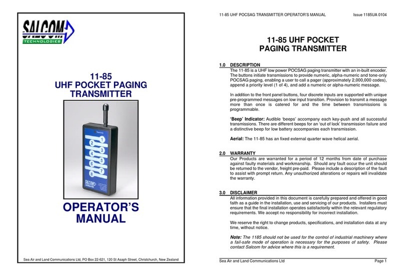
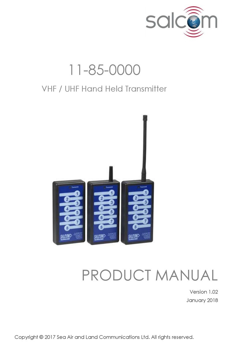
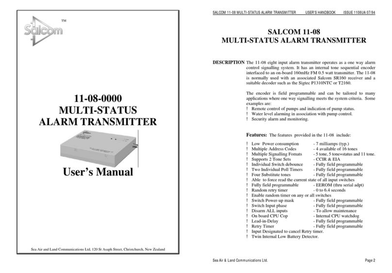
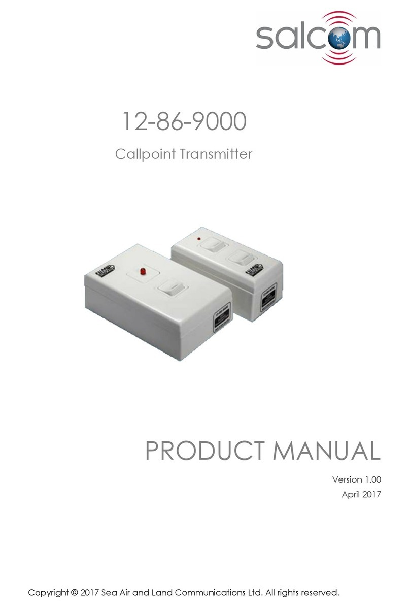
Salcom 12-86-9000 User manual

Copyright © 2017 Sea Air and Land Communications Ltd. All rights reserved.
12-8 -9000
UHF Call Point Transmitter
PRODUCT MANUAL
Version 1.01
February 2019

P a g e | 1
12-8 -9000 CALLPOINT TRANSMITTER Product Manual
Sea Air and Land Communications Ltd, 10 Vanadium Place, Addington, Christchurch 8024, New Zealand February 2019
Salcom Product Documentation
This document is designed to familiarise you with Salcom products and guide you through the
hardware, configuration, installation and overall system management.
Salcom is an environmentally conscious company and in an effort to conserve paper no longer
prints manuals with shipped products. All relevant documentation can be downloaded in PDF
form from our website www.salcom.com

P a g e | 2
12-8 -9000 CALLPOINT TRANSMITTER Product Manual
Sea Air and Land Communications Ltd, 10 Vanadium Place, Addington, Christchurch 8024, New Zealand February 2019
Warranty and Disclaimer
Salcom products are warranted for a period of 12 months from the date of purchase against
faulty materials and workmanship. Should any fault occur the unit should be returned to the
vendor, freight pre-paid. Please include a description of the fault to assist with prompt return. Any
unauthorised alterations or repairs will invalidate the warranty.
All information provided in this document is carefully prepared and offered in good faith as a
guide in the installation, use and servicing of Salcom products. Installers must ensure that the final
installation operates satisfactorily within the relevant regulatory requirements. Salcom accept no
responsibility for incorrect installation. We reserve the right to change products, specifications
and installation data at any time without notice.

P a g e | 3
12-8 -9000 CALLPOINT TRANSMITTER Product Manual
Sea Air and Land Communications Ltd, 10 Vanadium Place, Addington, Christchurch 8024, New Zealand February 2019
Product Overview
The 12-8 -9000 is a small, low cost, high specification Paging transmitter integrating the Salcom
12-8 -5000 Paging Transmitter PCB and inherits all 12-8 -5000 type approvals.
The 12-8 range of products are POCSAG direct to pager transmitters, allowing low cost systems
to be developed since intermediate receivers and transmitters are not required for short range
applications.
12-8 transmitters support up to 5 inputs, each of which can be programmed with up to a 35-
character message. Programming can either with a serial programming cable that can be
purchased separately or pre-programmed when supplied.
Although the 12-8 is a low power transmitter, when used as a call-point paging transmitter a
direct line of sight range of up to 800 metres can be expected. When used within buildings the
range will be reduced depending on the building.
The 12-8 -9000 fits the form factor of many standard electrical face plates, so that the transmitter
can remain in keeping with surrounding switchgear in cosmetically sensitive areas. By default the
12-8 -9000 is supplied with a mounting block, but can be flush mounted in the same manner as
most electrical switch plates if required.
The 12-8 -9000 is available in 2 sizes.

P a g e | 4
12-8 -9000 CALLPOINT TRANSMITTER Product Manual
Sea Air and Land Communications Ltd, 10 Vanadium Place, Addington, Christchurch 8024, New Zealand February 2019
Operation
Pressing the button will result in the red transmit LED illuminating, and the pre-programmed
POCSAG message being transmitted. The red transmit LED can also be used as an indication of
battery health, and should the LED be dim or fail to light, the CR2032 button cell should be
replaced.

P a g e | 5
12-8 -9000 CALLPOINT TRANSMITTER Product Manual
Sea Air and Land Communications Ltd, 10 Vanadium Place, Addington, Christchurch 8024, New Zealand February 2019
Programming
In order to program the12-8 -5000 PCB, programming software should be downloaded from the
Salcom website (www.salcom.co.nz).
A Salcom 12-47 programming lead is required to program
the 12-8 transmitters (the same lead used to program the
11-85 transmitters). This may be purchased separately. The
12-47 programming lead requires the availability of a PC
with a serial port, running windows XP.
Connect the 12-47 as shown below, with the dot (circled in
yellow) on the 12-47 socket towards the centre of the PCB
(mating with the square pad).
The 12-8 Programming Software allows the transmitter frequency and button messages to be
set.
1. Press “Connect”. The red LED will light, as a message is transmitted. After the message has
been sent, the green LED above the 4th button will light for approximately 1 second. The
status at the bottom of the 12-8 PSD will indicate if successfully connected.
2. Press “Read”. The current configuration is read from the 12-8 -5000.
3. Make any required changes.
4. Press the “Program” button.
5. Press “Disconnect”, then remove programming lead.

P a g e | 6
12-8 -9000 CALLPOINT TRANSMITTER Product Manual
Sea Air and Land Communications Ltd, 10 Vanadium Place, Addington, Christchurch 8024, New Zealand February 2019
General Configuration
Button Messages: Select the button to view the message, CapCode and beep level assigned
to that button. New button settings can be entered, but will not be written
until the program button is pressed. The program button only needs to be
pressed after all button details have been populated.
Fre uency: The transmit frequency between 440 and 470MHz to be set, 25kHz channel
spacing.
Pager Type: If set to “alphanumeric”, then any message can be set into the message box,
and can only be used with pagers that support alphanumeric messages.
When “numeric” is set then only 0,1,2,3,4,5, ,7,8,9,0,[,],-,E and U characters
can be used. Tone only pagers are supported by leaving the message box
empty.
Beep Level: Pager beep priority set - 1 highest, 4 lowest.
CapCode: Pager ID. Valid codes are 0000008 to 2000000

P a g e | 7
12-8 -9000 CALLPOINT TRANSMITTER Product Manual
Sea Air and Land Communications Ltd, 10 Vanadium Place, Addington, Christchurch 8024, New Zealand February 2019
Battery Replacement
Care must be taken when replacing the CR2032 coin cell. The battery must be fitted with the ‘+’
up and the ‘-’ touching the PCB. Incorrect battery installation will rapidly discharge the coin cell,
and may damage the transmitter.
After battery replacement, test that the 12-8 is functional by sending a test message and
verifying the red LED lights. If the unit fails to operate, remove battery, confirm correct battery
orientation and reinsert.

P a g e | 8
12-8 -9000 CALLPOINT TRANSMITTER Product Manual
Sea Air and Land Communications Ltd, 10 Vanadium Place, Addington, Christchurch 8024, New Zealand February 2019
Technical Specification
12-86-9000 – UHF Call Point Transmitter
Frequency Range 440-470MHz - UHF
Frequency Selection User configurable
Power Supply 3V CR2032 button cell
Battery Life Approx. 1000 transmissions
Approx. 10 years standby
Power Consumption Standby: 100nA
Transmit: 45mA
Transmit Power 10mW
Channel Spacing 25kHz
Modulation FSK with NRZ data
Deviation ±4.5kHz
Transmit Duty Cycle Up to 20%; Maximum 30 seconds on time
Baud Rate 512
Message Format POCSAG
Configuration Application 12-8 configuration tool
Programming Cable 12-47-0000 (Board header to DB9)
Can be used with a USB to RS232 DB9 Serial Adapter Cable
12-48-0000 (Board header to mini USB)
Serial Port 9 00, N, 8, 1; RS232
Discrete Inputs 1 or 2 button options
RF Connector Internal aerial
Environmental Protection Not suitable for outdoor use and should be protected from adverse
environmental conditions
Operating Temperature -10ºC to +55ºC (+14ºF to +131ºF)
Weight 90g
Enclosure Dimensions 50mm x 113mm x 4 mm (WxDxH)
Enclosure Material Plastic
Colour White
Type Approvals AS/NZS 47 9.1:2000 + Amendment 1:2002 (RF)
EN 300-224-2 (RF)
FCC CFR47 Part 90 (RF)
EN 301 489-2 V2.1.0 (EMC)
EN 0950-1:200 (Safety)

P a g e | 9
12-8 -9000 CALLPOINT TRANSMITTER Product Manual
Sea Air and Land Communications Ltd, 10 Vanadium Place, Addington, Christchurch 8024, New Zealand February 2019
How to Contact Us
Sea Air and Land Communications (Salcom) Ltd
10 Vanadium Place
Addington
Christchurch 8024
New Zealand
T: + 4 (0)3 379 2298
W: www.salcom.com
E: sales@salcom.com
Other manuals for 12-86-9000
1
Table of contents
Other Salcom Transmitter manuals

Salcom
Salcom 11-08-0000 User manual

Salcom
Salcom 12-62 POCSAG User manual

Salcom
Salcom 11-24-0000 User manual

Salcom
Salcom 12-86-0000 User manual

Salcom
Salcom 11-22-0000 User manual

Salcom
Salcom 12-86-9000 User manual

Salcom
Salcom 12-62-0000 User manual

Salcom
Salcom 12-86-0000 User manual

Salcom
Salcom 11-85-0000 User manual
Salcom
Salcom 20-62 User manual

Popular Transmitter manuals by other brands

E+E Elektronik
E+E Elektronik EE061 Series Technical data and operating instructions

Tekon
Tekon PLUS TWP DI Series installation guide

Boser
Boser LVDS-T4 Installation, quick start

CYP
CYP IP-7000TX Operation manuals

Moore Industries
Moore Industries TRY quick start guide

Moore Industries
Moore Industries IPT2 user manual