manuals.online logo
Brands
  1. Home
  2. •
  3. Brands
  4. •
  5. Salda
  6. •
  7. Air Handler
  8. •
  9. Salda VEKA INT W EKO User manual

Salda VEKA INT W EKO User manual

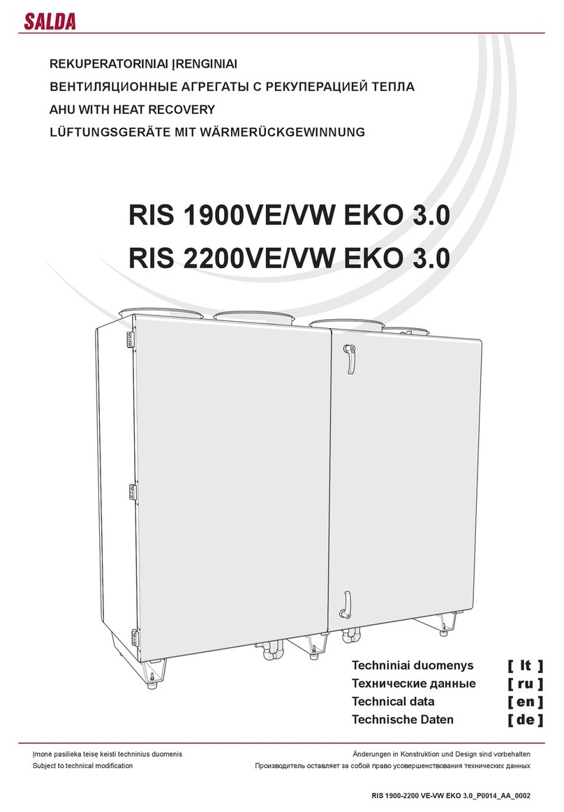
La société se réserve le droit de modier les données techniques Änderungen in Konstruktion und Design sind vorbehalten
Subject to technical modication Производитель оставляет за собой право усовершенствования технических данных
VEKA INT W EKO_P0053_AL_0003
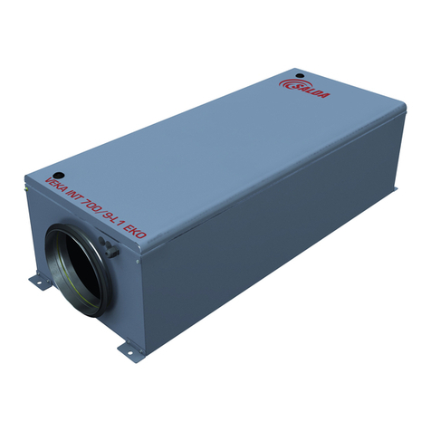
VEKA INT W EKO
CENTRALES DE TRAITEMENT D’AIR
ПРИТОЧНЫЕ АГРЕГАТЫ
AIR HANDLING UNITS
LÜFTUNGSGERÄTE
Instructions de montage [ fr ]
Инструкция по монтажу [ ru ]
Installation instruction [ en ]
Montageanleitung [ de ]
2www.salda.lt
VEKA INT W EKO
• Перед монтажом устройства необходимо
ознакомиться со всей приведенной в настоя-
щем документе документацией.
• Монтаж устройства может выполнять только
обученный и квалифицированный персонал,
знакомый с монтажом устройств данного
типа, их проверкой, обслуживанием и рабочи-
ми инструментами, необходимыми для прове-
дения монтажных работ.
• При установке изделия необходимо соблю-
дать международные требования к безопас-
ности механической и электротехнической
продукции, а также аналогичные требования
государства, в котором изделие будет монти-
роваться и эксплуатироваться.
• Если приведенная информация не ясна или
возникают сомнения относительно безопас-
ности монтажа и эксплуатации, просим об-
ращаться к производителю либо его предста-
вителю.
• Устройство может работать лишь при соблю-
дении ниже перечисленных условий.
• Категорически запрещается использовать
устройство не по назначению или в не пред-
усмотренных для работы условиях без полу-
чения на то письменного разрешения произво-
дителя либо его представителя.
• При обнаружении неисправности необходимо
уведомить об этом производителя либо его
представителя, охарактеризовать неисправ-
ность и сообщить данные, указанные на на-
клейке изделия.
• При возникновении неисправностей запре-
щается ремонтировать, разбирать устройство
без предварительного получения на то пись-
менного разрешения производителя либо его
представителя.
• Разборку, ремонтные работы или модифика-
цию устройства можно выполнять лишь после
получения письменного согласия на это произ-
водителя или его представителя.
• Потенциальный покупатель, перед тем как
заказать и установить изделие, должен убе-
диться, что изделие соответствует выбранным
условиям окружающей среды.
• Read all the information provided in this doc-
ument before installing the unit.
• Installation of the unit shall only be performed
by trained and qualied personnel aware of
installation of such type of units, inspection,
maintenance and tools required for installa-
tion works.
• While installing the unit, follow the interna-
tional and national requirements of mechani-
cal and electrotechnical safety of the country
where the product will be installed and used.
• If the provided information is unclear or any
doubts arise regarding safe installation and
operation, please contact the manufacturer
or its representative.
• The unit shall be operated only under the
conditions listed below.
• It is strictly forbidden to use the unit for non-
designed purposes or in contradiction to the
specied working conditions without written
permission of the manufacturer or its repre-
sentative.
• The manufacturer or its representative shall
be notied about any fault, including descrip-
tion of the fault and data specied on the
product’s label.
• Any repair or dismantle of the unit in case
of fault is forbidden without previous written
permission of the manufacturer or its repre-
sentative.
• Dismantling, repair or modication of the unit
shall be performed only upon prior written
consent of the manufacturer or its repre-
sentative.
• The end user shall ensure that the unit is
suitable for environmental conditions before
ordering and installing the unit.
• Vor der Montage des Gerätes sind sämtliche
in diesem Dokument enthaltenen Materialien
durchzulesen.
• Die Montage des Gerätes darf nur von geschul-
tem und qualiziertem Personal durchgeführt
werden, das mit der Montage, Kontrolle, War-
tung sowie entsprechendem Montagewerk-
zeug vertraut ist.
• Bei der Montage des Produktes sind die in-
ternationalen sowie örtlichen Vorschriften des
Betreiberlandes zur mechanischen und elekt-
rotechnischen Sicherheit einzuhalten.
• Sind die gelieferten Materialien unklar bzw. be-
stehen Zweifel hinsichtlich einer sicheren Mon-
tage und Bedienung, wenden Sie sich bitte an
den Hersteller bzw. seinen Vertreter.
• Das Gerät ist nur unter folgenden Bedingungen
zu betreiben.
• Es ist streng verboten, das Gerät nicht bestim-
mungsgemäß oder nicht unter vorgeschriebe-
nen Betriebsbedingungen einzusetzen, wenn
keine schriftliche Genehmigung des Herstellers
bzw. Vertreters dafür vorliegt.
• Im Störfall ist der Hersteller bzw. sein Vertre-
ter zu benachrichtigen, unter Angabe der Stö-
rungsbezeichnung sowie der Daten aus dem
Produktaufkleber.
• Es ist untersagt, bei Störungen das Gerät ohne
vorherige schriftliche Genehmigung des Her-
stellers bzw. seines Vertreters zu reparieren
oder zu zerlegen.
• Abbauten, Reparaturen und Veränderungen
am Gerät dürften nur mit schriftlicher Geneh-
migung des Herstellers bzw. seines Vertreters
durchgeführt werden.
• Vor der Bestellung und Montage des Gerätes
muss sich der Endkunde vergewissern, dass
das Gerät den gewählten Umgebungsbedin-
gungen entspricht.
• Lire toutes les informations du document
avant de monter la centrale.
• Le montage de la centrale ne doit être effec-
tué que par du personnel formé et qualié
connaissant le montage des centrales de
ce type, leur vérication, leur maintenance
et les outils requis pour effectuer les travaux
de montage.
• Lors du montage de la centrale, il faut res-
pecter les exigences mécaniques et élec-
trotechniques internationales et du pays, où
sera montée et utilisée la centrale, en ma-
tière de sécurité.
• Si les informations fournies ne sont pas
claires ou qu’il existe des doutes relatifs à un
montage et une utilisation sûrs, s’adresser au
fabricant ou à son représentant.
• La centrale ne peut fonctionner qu’aux condi-
tions mentionnées ci-dessous.
• Il est strictement interdit d’utiliser la centrale
à d’autres ns ou en contradiction avec les
conditions de fonctionnement énoncées sans
l’autorisation écrite du fabricant ou de son re-
présentant.
• En cas d’anomalie, il faut en informer le fabri-
cant ou son représentant avec la description
de l’anomalie et les données indiquées sur
l’étiquette de la centrale.
• En cas d’anomalie, il est interdit de réparer
ou de démonter la centrale sans une autori-
sation écrite préalable du fabricant ou de son
représentant.
• Le démontage, la réparation ou la modica-
tion de la centrale ne pourra être effectué
qu’avec le consentement écrit préalable du
fabricant ou de son représentant.
• L’acheteur initial doit s’assurer si la centrale
convient aux conditions de l’environnement
choisi avant de commander et de monter la
centrale.
• Toutes les centrales sont emballées à l’usine
de sorte qu’elles résistent aux conditions nor-
males de transport.
• Après le déballage du produit, veuillez vous
assurer s’il n’a pas été endommagé pendant
le transport. Il est interdit d’installer des cen-
trales endommagées !!!
• L’emballage est uniquement une mesure de
protection !
• Au moment du déchargement et du stoc-
kage des centrales, utiliser un équipement
de levage approprié an d’éviter dommages
et blessures. Ne pas soulever les centrales
par les câbles d’alimentation, les boîtiers de
câblage ou les piquages de l’air neuf, souf-
é, repris ou rejeté. Éviter les chocs et les
surcharges. Avant l’installation, les centrales
devront être stockées dans un local sec avec
une humidité de l’air relative n’excédant pas
70 % (à +20°C) et une température ambiante
moyenne comprise entre 0 % et + 30 %. Le
lieu de stockage doit être protégé de la saleté
et de l’eau.
• Les centrales peuvent être stockées et trans-
porter que si les piquages de branchement
sont en position horizontale.
• Il n’est pas recommandé de stocker pour une
période supérieure à un an. En cas de stoc-
kage supérieur à un an, il est nécessaire de
vérier avant l’installation si les roulements
tournent facilement (tourner la turbine à la
main).
• Все устройства упакованы на заводе так, что-
бы обеспечить их сохранность при нормаль-
ных условиях перевозки.
• После распаковки устройства проверьте, не
было ли оно повреждено при транспортиров-
ке. Монтаж поврежденных устройств запре-
щается!!!
• Упаковка является только защитным сред-
ством!
• При разгрузке и складировании устройств
используйте надлежащее подъемное обору-
дование во избежание причинения ущерба и
травм. Не поднимайте устройства за провода
питания, клеммные коробки, фланцы подачи
или вытяжки воздуха. Избегайте сотрясений и
ударных перегрузок. До установки складируй-
те устройства в сухом помещении, в котором
относительная влажность воздуха не превы-
шает 70% (при температуре +20°C), средняя
температура находится в пределах от +0°C до
+30°C. Место складирования должно быть за-
щищено от грязи и воды.
• Устройства можно складировать и транспор-
тировать лишь так, чтобы соединительные
фланцы находились в горизонтальном поло-
жении.
• Не рекомендуется хранить устройства на
складе более одного года. При условии более
длительного складирования перед монтажом
необходимо проверить, легко ли вращаются
подшипники (покрутить крыльчатку рукой).
• All units are packed in the factory to with-
stand regular conditions of transportation.
• Upon unpacking, check the unit for any dam-
ages caused during transportation. It is for-
bidden to install damaged units!!!
• The package is only a protection means!
• At unloading and storing the units, use suit-
able lifting equipment to avoid damages and
injuries. Do not lift units by holding on power
supply cables, connection boxes, air intake or
discharge anges. Avoid hits and shock over-
loads. Before installation units shall be stored
in a dry room with the relative air humidity not
exceeding 70% (at +20°C) and with the aver-
age ambient temperature ranging between
0°C and +30°C. The place of storage shall be
protected against dirt and water.
• During transportation and storage of the
units, the connection anges must be in hori-
zontal position.
• The storage is not recommended for a pe-
riod longer than one year. In case of storage
longer than one year, it is necessary to check
free rotation of bearings before installation
(turn the impeller by hand).
• Alle Geräte sind werksseitig so verpackt,
dass sie den normalen Transportbedingungen
standhalten können.
• Nach Auspacken des Gerätes überprüfen Sie,
ob es beim Transport nicht beschädigt wurde.
Beschädigte Geräte dürfen nicht montiert wer-
den!!!
• Die Verpackung ist nur eine Schutzmaßnahme!
• Beim Ausladen und Lagern der Geräte verwen-
den Sie geeignete Hebezeuge, um Schäden
und Verletzungen zu vermeiden. Heben Sie die
Geräte nicht an Netzkabeln, Anschlusskästen,
Zu- und Abluftstutzen. Vermeiden Sie Stöße
und Schläge. Vor der Montage lagern Sie die
Geräte in einem trockenen Raum, wo die re-
lative Luftfeuchte höchstens 70% (bei +20°C)
beträgt und die durchschnittliche Umgebungs-
temperatur zwischen +0°C und +30°C liegt.
Der Lagerort muss vor Schmutz und Wasser
geschützt sein.
• Die Geräte sind mit Anschlussstutzen in hori-
zontaler Lage zu lagern und zu transportieren.
• Eine Lagerung länger als ein Jahr ist nicht
empfehlenswert. Bei einer Lagerung länger als
ein Jahr sind die Lager vor der Montage auf
Freigängigkeit zu prüfen (Flügelrad von Hand
drehen).
• Aérotherme eau chaude.
• Ventilateurs efcaces et silencieux.
• Moteurs de ventilateurs EC.
• Débit d’air réglable de manière uniforme.
• Régulation de la température de l’air soufé.
• Isolation acoustique et thermique des parois
externes 30 mm.
• Contrôle automatique intégré.
• Montage du clapet de l’air soufé motorisé.
• Montage d’un système de xation de pollu-
tion des ltres.
• Water heater.
• Efcient and silent fans.
• EC fan motors.
• Evenly adjusted air ow.
• Adjusted supply air temperature.
• Acoustic and thermal insulation of external
walls: 30mm.
• Installed control automation.
• Installed motorized supply air damper.
• Installed lter pollution measuring system.
• Wasserheizregister.
• Leistungsstarke und geräuscharme Ventilato-
ren.
• EC -Motoren.
• Stufenlose Regelung des Luftstroms.
• Regelbare Zulufttemperatur.
• 30 mm starke Geräusch- und Wärmeisolation
der Außenwände.
• Eingebaute Steuerautomatik.
• Integrierte motorisch gesteuerte Zuluftklappe.
• Integriertes System zur Filterverschmutzungs-
kontrolle.
• Водяной нагреватель.
• Производительные и тихо работающие вен-
тиляторы.
• ЕС-двигатели вентиляторов.
• Плавно регулируемый поток воздуха.
• Регулируемая температура приточного воз-
духа.
• Толщина звуко- и теплоизоляции наружных
стенок – 30 мм.
• Вмонтирована автоматика управления.
• Вмонтирована моторизованная заслонка при-
точного воздуха.
• Вмонтирована система фиксации степени за-
грязнения фильтров.
3
www.salda.lt
VEKA INT W EKO
• Les centrales ne doivent être utilisées qu’à
l’intérieur à une température allant de 0°C à
+ 40°C et une humidité relative inférieure à
70 %.
• Il est interdit d’utiliser les centrales dans un
environnement potentiellement explosif.
• Les centrales sont conçues pour un apport
dans les systèmes de ventilation et climatisa-
tion de l’air neuf (sans composés chimiques
stimulant la corrosion des métaux, sans
substances agressives au zinc, plastique et
caoutchouc, sans particules de matériaux
durs, adhésifs et à bres) d’un local.
• Il doit être tenu compte de la température du
débit d’air maximale et minimale autorisée
allant de -20°C à + 40°C.
• L’humidité de l’air soufé extérieur maximale
est de 90%.
• La température de l’eau maximale est de
100°C.
• La pression maximale est de 1,6 MPa.
• Les indicateurs de la qualité de l’eau ne doi-
vent pas être supérieurs à ceux indiqués.
- quantité totale d’ions de chlore et de soufre :
150 mg/l au maximum (50 mg/l au maximum si
les tuyaux sont en cuivre) ;
- quantité d’oxygène : 0,1 mg/l au maximum ;
- l’acidité de l’eau (PH) doit rester à 8,0-9,5 ;
- dureté totale : 4,0 mval/l.
• Устройство предназначено только для экс-
плуатации в закрытых помещениях при темпе-
ратуре воздуха от 0 до +40 C
°
и относительной
влажности не выше 70 проц.
• Устройства запрещается использовать в по-
тенциально взрывоопасной среде.
• Устройство предназначено для подачи в си-
стемы вентиляции и кондиционирования толь-
ко чистого воздуха (без химических соедине-
ний, способствующих коррозии металлов; без
веществ, агрессивных по отношению к цинку,
пластмассе, резине; без частиц твердых, лип-
ких и волокнистых материалов).
• Следует обратить внимание на минимально
и максимально допустимую температуру воз-
душного потока – от -20 до +40 C
°
.
• Максимальная относительная влажность при-
точного наружного воздуха – 90 проц.
• Максимальная температура воды – +100 C
°
.
• Максимальное давление – 1,6 МПа.
• Показатели качества воды должны соответ-
ствовать следующим величинам:
– общее количество ионов хлора и серы – не
более 150 мг/л (если трубы медные – не более
50 мг/л);
– кислорода не больше 0,1 мг/л;
– кислотность воды (pH) в пределах 8,0-9,5;
– общая жесткость не выше 4,0 мг-экв/л.
• Unit is designed for indoor use only at tem-
perature between 0°C and +40°C and rela-
tive humidity not exceeding 70%.
• It is forbidden to use the units in potentially
explosive environment.
• Unit is designed for ventilation and condition-
ing systems to supply to a room only clean air
(free of chemical compounds causing metal
corrosion, of substances aggressive to zinc,
plastic and rubber, and of particles of solid,
adhesive and bred materials).
• Minimum and maximum permissible air ow
temperature between -20°C and +40°C.
• Maximum water temperature 100°C.
• Maximum pressure 1.6 MPa.
• Water quality values must not exceed the fol-
lowing values:
- total amount of chlorine and sulphur ions must
not exceed 150 mg/l (in case of copper pipes
must not exceed 50 mg/l);
- the amount of oxygen must not exceed
0.1 mg/l;
- water acidity (pH) must be retained between
8.0 and 9.5;
- total hardness must not exceed 4.0 mval/l.
• Das Gerät ist für den Betrieb ausschließlich in
geschlossenen Räumen bei Temperaturen zwi-
schen 0 ºC und +40 °C und relativer Feuchte
von höchstens 70% bestimmt.
• Die Geräte dürfen nicht in einer explosionsge-
fährdeten Atmosphäre betrieben werden.
• Das Gerät ist dazu bestimmt, in den Lüftungs-
und Klimaanlagen ausschließlich saubere Luft
(ohne chemische Verbindungen, die Metallkor-
rosion hervorrufen; ohne aggressive Substan-
zen, die Zink, Kunststoff und Gummi angreifen;
ohne Partikeln von festen, klebenden sowie
faserigen Materialien) in den Raum zu liefern.
• Es ist die minimal und maximal zulässige Luft-
strömungstemperatur zwichen -20 und +40 °C
zu beachten.
• Maximale Zuluftfeuchte 90%
• Maximale Wassertemperatur 100°C.
• Maximaler Druck 1,6 MPa .
• Wasserqualitätswerte sollen die angegebenen
Werte nicht überschreiten:
- Gesamtgehalt an Chlor- und Schwefelionen –
höchstens 150 mg/l (bei Kupferrohren – höchstens
50 mg/l);
- Sauerstoffgehalt höchstens 0,1 mg/l;
- Säuregehalt des Wassers (pH) soll zwischen
8,0 und 9,5 bleiben;
- Gesamthärte höchstens 4,0 mval/l.
• Ne pas utiliser cette centrale dans d’autres
buts que ceux prévus dans sa conception.
• Ne pas démonter et modier la centrale. Cela
peut provoquer une panne mécanique ou
même des blessures graves.
• Utiliser des vêtements de travail spéciaux
pour monter et entretenir la centrale. Soyez
prudent : les angles et les bords de la cen-
trale et de ses composants peuvent être cou-
pants et provoquer des blessures.
• Ne pas porter près de la centrale de vête-
ments ottants qui pourraient être aspirés
dans le ventilateur en marche.
• Tous les produits emballés à l’usine ne sont
pas prêts à l’emploi. Les centrales ne peu-
vent être utilisées qu’après raccordement
aux conduits d’air ou après installation de
grilles de protection sur les piquages d’air
neuf/soufé et repris/rejeté.
• Ne pas mettre les doigts ou autres objets
dans les grilles de protection des piquages
de centrale de traitement d’air ou dans le
conduit d’air raccordé. Si un corps étranger
entre dans la centrale, déconnecter tout de
suite de la source d’alimentation électrique.
Avant d’éliminer le corps étranger, s’assu-
rer que tout mouvement mécanique est ar-
rêté dans la centrale. S’assurer aussi qu’une
mise en marche accidentelle de la centrale
est impossible.
• Éviter un contact direct avec le ux d’air in-
sufé et rejeté de la centrale.
• Ne pas connecter la centrale à un réseau
électrique autre que celui indiqué sur l’éti-
quette du produit collée sur le boîtier de la
centrale.
• Ne jamais utiliser de câble d’alimentation
endommagé.
• Ne jamais toucher avec les mains humides
les câbles d’alimentation connectés au ré-
seau électrique.
• Ne jamais plonger les rallonges et les prises
dans l’eau.
• Ne pas monter ni utiliser la centrale sur des
surfaces inégales ou autres plans instables.
• Ne jamais utiliser cette centrale dans un envi-
ronnement propice aux explosions et conte-
nant des substances agressives.
• Не используйте данное устройство в целях, не
указанных в его предназначении.
• Не разбирайте и не модифицируйте никоим
образом устройство. Это может вызвать меха-
ническую поломку или даже травму.
• При монтаже и обслуживании устройства
пользуйтесь специальной рабочей одеждой
и обувью. Будьте осторожны: углы и кромки
устройства и составляющих его частей могут
быть острыми и ранящими.
• Не находитесь рядом с вентилятором в сво-
бодной одежде, которая может быть втянута в
работающий вентилятор.
• Все упакованные на заводе устройства не яв-
ляются полностью готовыми к эксплуатации.
Устройства могут эксплуатироваться лишь по-
сле подсоединения к воздуховодам или после
установки защитных решеток в приточное и
вытяжное отверстия.
• Не просовывайте пальцы или другие пред-
меты в защитные решетки приточных и вы-
тяжных отверстий или в подсоединенный воз-
духовод. При попадании любого постороннего
предмета в устройство, немедленно отклю-
чите его от источника электропитания. Перед
устранением постороннего предмета убеди-
тесь, что всякое механическое движение в
устройстве прекращено. Убедитесь также, что
случайное включение устройства невозможно.
• Избегайте непосредственного контакта с по-
током воздуха, всасываемого и удаляемого
устройством.
• Не подключайте устройство к электросети
иных параметров, нежели это указано на на-
клейке изделия на корпусе устройства.
• Никогда не используйте поврежденный про-
вод питания.
• Никогда не прикасайтесь мокрыми руками к
подключенным к электросети кабелям пита-
ния.
• Никогда не погружайте провода удлинителей и
штыревые разъемы в воду.
• Не устанавливайте и не эксплуатируйте
устройство на неровных поверхностях и иных
неустойчивых плоскостях.
• Никогда не эксплуатируйте данное устройство
во взрывоопасной и содержащей агрессивные
вещества среде.
• Do not use this unit for purposes other than
those provided in its design.
• Do not dismantle and modify the unit. Such
actions can cause mechanical fault or even
injury.
• Use special working clothes when installing
and maintaining the unit. Be careful – angles
and edges of the unit and its components can
be sharp and cause injuries.
• Being near the unit, do not wear free stream-
ing clothes that could be sucked into the op-
erating fan.
• All products packed in the factory are not pre-
pared for eventual operation. The units can
be used only by connecting them to air ducts
or by installing protection grating in air intake
and discharge openings.
• Do not put ngers or any other objects into
protection grating of air intake and discharge
or into connected air duct. In case any foreign
body get into the unit, disconnect the power
supply source immediately. Before removal
of foreign body, make sure that any me-
chanical movement in the unit has stopped.
In addition, make sure that the accidental
switching-on of the unit is impossible.
• Avoid direct contact with the ow of supplied
and extracted air.
• Do not connect the unit to the mains other
than indicated in the manufacturer’s label on
the casing of the unit.
• Never use a damaged power supply cable.
• Never touch with wet hands the power supply
cables connected to the mains.
• Never dip extension cords and plugs in water.
• Do not install and use the unit on uneven sur-
faces or other unstable planes.
• Never use this unit in the environment condu-
cive to explosion and containing any aggres-
sive materials.
• Setzen Sie das Gerät ausschließlich bestim-
mungsgemäß ein.
• Unternehmen Sie keine Umbauten und Ver-
änderungen am Gerät. Dies kann zu mecha-
nischen Beschädigungen und Verletzungen
führen.
• Bei Montage und Wartung des Gerätes tragen
Sie spezielle Arbeitskleidung. Seien Sie vor-
sichtig – die Ecken und Kanten des Gerätes
und seiner Bauteile können scharf sein und
Verletzungen zufügen.
• Tragen Sie am Gerät keine weite Kleidung, die
in den funktionierenden Ventilator eingezogen
werden kann.
• Sämtliche im Werk verpackten Erzeugnisse
sind noch nicht einsatzbereit. Die Geräte dür-
fen nur nach dem Anschluss an die Luftleitun-
gen bzw. nach dem Einbau der Schutzgitter
in die Öffnungen für Zu- und Abluft in Betrieb
genommen werden.
• Greifen Sie nicht und stecken Sie keine Ge-
genstände in die Schutzgitter für Zu- und Abluft
bzw. in die angeschlossene Luftleitung. Sollte
ein beliebiger Fremdkörper in das Gerät gera-
ten, ist dieses sofort vom Netz zu trennen. Vor
dem Entfernen des Fremdkörpers ist sicherzu-
stellen, dass jegliche mechanische Bewegung
im Gerät zum Stillstand gekommen ist. Außer-
dem ist sicherzustellen, dass ein ungewolltes
Wiedereinschalten des Gerätes nicht möglich
ist.
• Vermeiden Sie einen direkten Kontakt zur Zu-
und Abluftströmung des Gerätes.
• Schließen Sie das Gerät an kein anderes
Stromnetz an, als im Produktaufkleber auf dem
Gerätegehäuse angegeben.
• Verwenden Sie niemals ein beschädigtes Netz-
kabel.
• Nehmen Sie niemals ein am Netz angeschlos-
senes Kabel in nasse Hände.
• Tauchen Sie Verlängerungskabel oder Steck-
verbindungen niemals ins Wasser.
• Montieren und betreiben Sie das Gerät niemals
auf unebenen oder sonstigen instabilen Ober-
ächen.
• Setzen Sie das Gerät niemals in einer explo-
sionsgefährdeten oder aggressive Materialien
enthaltenden Atmosphäre ein.
4www.salda.lt
VEKA INT W EKO
Stouch Remote controller
Ptouch Remote controller
AF Set of spare lters
AM Mixing point
VP Thermic water valve actuator
VV 3-way water valve
CO2CO2 transmitter
DF Differential pressure transmitter
IV Insulated duct fan AKU EKO
Stouch Пульт управления
Ptouch Пульт управления
AF Комплект филтров
AM Регулировочный узел
VP Тепловой привод клапана
VV 3-х ходовой клапан
CO2CO2преобразователь
DF Дифференциальный датчик
давления
IV Канальныи изолираван
вентилятор AKU EKO
Stouch Bedienpult
Ptouch Bedienpult
AF Ersatzltergarnitur
AM Regelungseinheit
VP Thermische Stellantriebe für Heiz-
körperventile
VV 3 Wege-Ventil
CO2CO2 sender
DF Differenzdruck-Messumformer
IV Schallgedämmte Kanalventilatoren
AKU EKO
свежий воздух
приточный воздух
fresh air
supply air
Aussenluft
Zuluft
IV
M4
M6
M5
Stouch Ptouch
PV supply air fan
KV water heater
PF lter for supply air
SK Air damper
SP actuator
SD differential pressure switch
TJ air temperature sensor
TV temperature sensor
T1 antifrost thermostat
PV ventilateur d’air neuf
KV aérotherme eau chaude
PF ltre de l’air neuf
SK clapet
SP servomoteur du clapet
SD sonde de pression
TJ sonde de température de l’air
TV sonde antigel
T1 thermostat antigel
PV вентилятор приточного воздуха
KV водяной нагреватель
PF фильтр для свежего воздуха
SK Заслонка
SP электропривод
SD датчик давления
TJ датчик температуры воздуха
TV датчик противозамерзания
T1 термостат противозамерзания
PV Zuluftventilator
KV Warmwasserheizregister
PF Außenluftlter
SK
Luftklappe
SP Klappenmotor
SD Druckwächter
TJ Luftteperatur Fühler
TV Frostschutzfühler
T1 Frostschutzthermostat
P Boîtier de commande
AF Filtres de rechange
AM Nœud de réglage RMG
VP Servomoteur thermique du clapet
de l’eau
VV Robinet d’eau à trois voies
CO2Convertisseur de CO²
DF Capteur de pression différentielle
IV Caisson de ventilation insonorisé de
gaine AKU EKO
air neuf
air soufé
5
www.salda.lt
VEKA INT W EKO
• Монтажные работы могут выполнять только
обученные и квалифицированные работники.
• Устройство должно быть установлено прочно
и жестко, что обеспечит безопасную его экс-
плуатацию.
• Перед подсоединением к системе воздухово-
дов, отверстия вентиляционного устройства
для соединения с воздуховодами должны
быть закрыты.
• Не подсоединяйте колена рядом с монтаж-
ными фланцами устройства. Минимальный
отрезок прямого воздуховода между устрой-
ством и первым ответвлением воздуховодов
в канале забора воздуха должен составлять
1хD, в канале отвода воздуха – 3хD, где D –
диаметр воздуховода. Для прямоугольных воз-
духоводов D=, где B – ширина, а H – высота
воздуховода.
• При подсоединении воздуховодов обратите
внимание на направление воздушного потока,
указанное на корпусе устройства.
• При подсоединении вентилятора к системе
воздуховодов, рекомендуем использовать ак-
сессуары – крепежные обоймы или гибкие со-
единения, в зависимости от типа подключения
устройства (рис. 1). Это уменьшит передачу
вибрации от вентилятора к системе воздухо-
водов и на окружающую среду.
• Монтаж необходимо произвести так, чтобы вес
системы воздуховодов и всех ее компонентов
не нагружал вентиляционное устройство.
• Вибрация может передаваться через пол,
стены или потолок. Если имеется такая воз-
можность, с целью снижения уровня шума
необходимо дополнительно изолировать пол,
стены или потолок.
• Если существует возможность попадания кон-
денсата или воды на двигатель, необходимо
установить наружные средства защиты.
• Приточный агрегат можно устанавливать на
полу или потолке, как указано на рис. 2. Для
этой цели имеются 4 ножки крепления (рис. 3).
• Недопустимая установка устройства показана
на рис. 4.
• ВАЖНО. Устанавливать устройство можно
лишь таким образом, чтобы вся крепящаяся
поверхность устройства полностью прилегала
к монтируемой поверхности. Удалить защит-
ный щит (рис. 5).
• При установке необходимо оставить достаточ-
но места для открывания дверцы обслужива-
ния устройства (рис. 6).
• При недостатке места дверцу обслуживания
можно снять, как показано на рис. 7 а).
• В случае необходимости предусмотрена воз-
можность изменения стороны открывания
дверцы обслуживания устройства (рис. 7).
• При подключении водяного нагревателя масса
водного трубопровода и тепловые напряже-
ния не должны переноситься на патрубки на-
гревателя.
• При монтаже резьбовых соединений труб по-
дачи воды и нагревателей должны использо-
ваться два гаечных ключа (рис. 8).
• Трубопроводы к нагревателю подсоединяются
так, чтобы при проведении работ по обслужи-
ванию и ремонту можно было бы быстро раз-
монтировать и вынуть нагреватель из корпуса
устройства.
• Трубопроводы с подающими и возвратными
теплоносителями должны подключаться так,
чтобы нагреватель работал в направлении,
противоположном направлению движения
воздушного потока. Если нагреватель рабо-
тает в режиме потоков того же направления,
снижается средняя разница температур, вли-
яющая на производительность нагревателя
(рис. 9).
• Смонтируйте датчик температуры приточного
воздуха в канале приточного воздуха. Датчик
устанавливается на максимальном расстоя-
нии от устройства до первого ответвления или
• Installation works shall be performed only by
trained and qualied personnel.
• Unit shall be installed rmly and tightly to en-
sure safe operation.
• Before connecting to the air duct system, the
connection openings of ventilation system air
ducts shall be closed.
• Do not connect the bends near the connec-
tion anges of the unit. The minimum dis-
tance of the straight air duct between the
unit and the rst branch of the air duct in the
suction air duct must be 1xD, in air exhaust
duct 3xD, where D is diameter of the air duct.
For rectangular air ducts D=, where B – width
of the air duct and H – height of the air duct.
• When connecting air ducts, consider the di-
rection of air ow indicated on the casing of
the unit.
• Depending of the type of the unit connection
(Pic 1), it is recommended to use the acces-
sories – clamps or exible connections for
connection of the air supply unit to the air
duct system. This will reduce vibration trans-
mitted by the unit to the air duct system and
environment.
• Installation shall be performed in such man-
ner that the weight of the air duct system and
its components would not overload the ven-
tilation unit.
• Vibration may also be transmitted through
the oor, walls or ceiling. If possible, the oor,
walls or ceiling shall be additionally insulated
in order to suppress the noise.
• The possible access of condensate or water
to the motor shall be prevented by external
protective means.
• Ventilation unit can be installed on the oor
or ceiling as shown in Pic. 2. 4 fastening legs
are supplied for this purpose (Pic. 3).
• Inappropriate way of the unit installation is
shown in Pic. 4.
• IMPORTANT. The unit shall be installed only
in such a way that the entire surface of the
unit fully adhere to the surface of installation .
Remove the protective shield (Pic. 5).
• During installation enough space shall be
retained for opening of the unit maintenance
door. (Pic. 6).
• If there is not enough space, the mainte-
nance door may be removed as it is shown
in Pic. 7 a).
• If necessary, the option to change the open-
ing side of the fan maintenance door is pro-
vided (Pic. 7).
• When connecting the water heater, the
weight of water pipes and heat tensions must
not be transferred on the heater branches.
• When mounting threaded connections of
supply pipes and heaters, two spanners must
be used (Pic. 8).
• Pipes are connected to the heater in such
manner that they could be easily disassem-
bled and the heater could be removed from
the unit casing when performing service or
repair works.
• Pipes with supply and return heat carriers
must be connected in such way that the
heater would work in the opposite direction of
the air ow. If the heater works in the mode of
the same directions, the mean temperature
difference decreases which affects the heater
efciency (Fig. 9).
• Install the supply air temperature sensor to
the supply air duct. The sensor is installed as
far as possible from the unit to the rst branch
or turning of the air ducts.
• Die Montagearbeiten dürfen nur von geschul-
tem und qualiziertem Personal ausgeführt
werden.
• Das Gerät ist fest und starr zu montieren, damit
ein sicherer Betrieb gewährleistet ist.
• Vor dem Anschließen an das Luftleitungssys-
tem sind die Anschlussöffnungen für Luftleitun-
gen abzudecken.
• Schließen Sie keine Bögen in der Nähe von
Geräteanschlussstutzen an. Der Mindestab-
stand einer geraden Luftleitung zwischen dem
Gerät und der ersten Abzweigung in der Zuluft-
leitung muss 1xD, in der Abluftleitung 3xD be-
tragen (D - Durchmesser der Luftleitung). Für
rechteckige Luftleitungen gilt D=, B- Breite der
Luftleitung, H- Höhe der Luftleitung.
• Beim Anschließen der Luftleitungen ist auf
die am Gerätegehäuse angegebene Luftströ-
mungsrichtung zu achten.
• Beim Anschließen des Zuluftgerätes an das
Luftleitungssystem empfehlen wir, Zusatzkom-
ponenten zu verwenden: Bügel bzw. exible
Verbindungen, abhängig von der Anschlussart
des Gerätes (Bild 1). Dies verringert die vom
Gerät an das Luftleitungssystem und die Um-
gebung übertragenen Schwingungen.
• Die Montage ist so durchzuführen, dass durch
das Gewicht des Luftleitungssystems und aller
seiner Bauteile keine Belastungen am Lüf-
tungsgerät auftreten.
• Die Übertragung der Schwingungen kann über
die Fußböden, Wände oder Decken erfolgen.
Besteht diese Möglichkeit, sollten die Fußbö-
den, Wände oder Decken zusätzlich isoliert
werden, um den Lärm abzudämpfen.
• Besteht die Möglichkeit zum Eindringen von
Kondensat bzw. Wasser in den Ventilator, sind
externe Schutzvorrichtungen anzubringen.
• Das Lüftungsgerät kann auf dem Boden oder
an der Decke montiert werden, siehe Bild 2.
Dafür sind 4 Befestigungsfüße vorgesehen
(Bild 3).
• Unzulässige Montage des Gerätes siehe Abb.
4.
• WICHTIG. Das Gerät ist nur so zu montieren,
dass die ganze Befestigungsäche vollständig
auf der Montageäche auiegt. Entfernen Sie
die Schutzscheibe (Bild 5).
• Bei Montage ist ein ausreichender Schwenkbe-
reich für die Wartungstür vorzusehen (Bild 6).
• Ist kein ausreichender Schwenkbereich vor-
handen, kann die Wartungstür abgenommen
werden, siehe Bild 7 a).
• Bei Bedarf besteht die Möglichkeit, die Öff-
nungsseite der Wartungstür zu ändern (Bild 7).
• Beim Anschließen des Wasserheizregisters
darf kein Gewicht und keine Wärmespannun-
gen der Wasserleitungen auf die Stutzen des
Heizregisters übertragen werden.
• Bei Montage von Verschraubungen der Rohr-
leitungen und Heizregister sind zwei Maul-
schlüssel zu verwenden (Bild 8).
• Die Rohrleitungen sind am Heizregister so
anzuschließen, dass sie bei Wartungs- und
Instandsetzungsarbeiten schnell demontiert
werden können, um das Heizregister aus dem
Gerätegehäuse herauszunehmen.
• Der Zu- und Rücklauf der Wärmeübertrager
ist so anzuschließen, dass das Heizregister
in entgegengesetzter Luftströmungsrichtung
funktioniert. Wird das Heizregister in gleicher
Strömungsrichtung betrieben, verringert sich
die mittlere Temperaturdifferenz, die die Leis-
tung des Heizregisters beeinusst (Bild 9).
• Bauen Sie den Zulufttemperaturfühler in die
Fig. 1 Рис. 1 Pic. 1 Bild 1 Fig. 2 Рис. 2 Pic. 2 Bild 2 Fig. 3 Рис. 3 Pic. 3 Bild 3
• Le montage ne peut être effectué que par du
personnel formé et qualié.
• La centrale doit être montée solidement et
fermement an de garantir une utilisation
sûre.
• Avant le raccordement à la gaine de conduits
d’air, les piquages du dispositif de ventilation
doivent être fermés.
• Ne pas raccorder de coudes près des pi-
quages de raccordement de la centrale.
La distance minimale du conduit d’air droit
entre la centrale et la première branche
des conduits d’air doit être de 1xD dans le
conduit d’aspiration et de 3xD dans le conduit
d’extraction de l’air, où D est le diamètre du
conduit d’air. Pour les conduits d’air rectan-
gulaires D=, où B est la largeur du conduit
d’air et H la hauteur du conduit d’air.
• En raccordant les conduits d’air, faire atten-
tion à la direction de ux d’air indiquée sur le
panneau de la centrale.
• Pour le raccordement des piquages à la
gaine de conduits d’air, nous recommandons
d’utiliser des accessoires : les manchettes
ou les raccords exibles en fonction du type
de raccordement de la centrale (Fig. 1). Cela
réduira les vibrations de la centrale sur le
système de conduits d’air et l’environnement.
• Le montage doit être effectué de sorte que le
poids du système de conduits d’air et de tous
ses composants ne surcharge pas le disposi-
tif de ventilation.
• Des vibrations peuvent être transmises par
le sol, les murs ou le plafond. Si possible, il
est nécessaire d’isoler en complément le sol,
les murs ou le plafond an d’étouffer le bruit
causé
• S’il y a la possibilité d’un accès à la centrale
de condensat ou d’eau, il est nécessaire
d’installer des mesures de protection ex-
ternes.
• Il est possible de monter le dispositif de venti-
lation sur le sol ou au plafond comme indiqué
Fig. 2. Quatre pieds de support sont préparés
dans ce but (Fig. 3).
• Il est interdit de monter la centrale comme
indiqué Fig. 4.
• Important : la centrale doit être montée de
telle façon que toute la surface de xage de
la centrale soit complètement collée à la sur-
face de montage (Fig.5)
• Lors du montage, il est nécessaire de laisser
sufsamment de place pour ouvrir les portes
de service de la centrale (Fig. 6).
• En cas de place insufsante, il est possible
d’enlever les portes de service comme indi-
qué Fig. 7 a).
• Si nécessaire, la possibilité est prévue de
changer le côté d’ouverture des portes de
service de la centrale (Fig. 7).
• Lors du branchement de l’aérotherme eau
chaude, la masse de la canalisation d’eau et
les tensions thermiques ne doivent pas être
transférées sur la tubulure de raccordement
de la batterie.
• Lors du montage des connexions des tuyaux
d’alimentation et des batteries taraudés, il
faut utiliser deux clés à écrou (Fig. 8).
• Les tuyaux sont connectés à la batterie de
telle sorte qu’en effectuant les travaux de
maintenance et de réparation il soit possible
de démonter et de retirer rapidement les
tuyaux du panneau de la centrale.
• Les tuyaux avec les caloporteurs d’alimen-
tation et de retour doivent être raccordés de
sorte que la batterie fonctionne dans la direc-
tion inverse au ux d’air. Lorsque la batterie
6www.salda.lt
VEKA INT W EKO
Fig. 7 Рис. 7 Pic. 7 Bild 7
Fig. 8 Рис. 8 Pic. 8 Bild 8
a
a
b
b
c
c d
Fig. 4 Рис. 4 Pic. 4 Bild 4 Fig. 5 Рис. 5 Pic. 5 Bild 5 Fig. 6 Рис. 6 Pic. 6 Bild 6
7
www.salda.lt
VEKA INT W EKO
e
• Des dispositifs ont des pièces en rotation
et sont connectés au réseau d’alimentation.
Cela provoquer des risques pour la santé
et la vie des personnes. Par conséquent,
il est obligatoire de respecter les exigen-
ces de sécurité lors de l’exécution travaux
d’installation. En cas de doute concernant la
sécurité de l’installation et du fonctionnement
de la centrale, prière de contacter le fabricant
ou son représentant.
• Le montage ne peut être effectué que par du
personnel formé et qualié.
• Assurez-vous que les spécications du rése-
au auquel vous connectez la centrale corres-
pondent aux spécications indiquées dans
l’étiquette sur le caisson.
• Le câble d’alimentation sélectionné doit
correspondre à la puissance de la centrale
(tableau 1).
• L’appareil doit être raccordé selon un sché-
ma de raccordement électrique comme cela
est indiqué dans ce document (g. 10) et
comme cela est indiqué sous le couvercle de
raccordement de la régulation automatique.
• Le câble d’alimentation et le dispositif de pro-
tection (commutateur automatique avec une
caractéristique C) de la centrale sont sélecti-
onnés selon le tableau 1.
• L’appareil doit être correctement mis à la
• Устройства имеют вращающиеся части и под-
ключаются к электросети. Это может пред-
ставлять опасность для здоровья и жизни
человека. Поэтому при выполнении монтаж-
ных работ необходимо соблюдать требования
безопасности. В случае возникновения со-
мнений относительно безопасной установки и
эксплуатации изделия, просим обращаться к
производителю или его представителю.
• Монтажные работы могут выполнять только
обученные и квалифицированные работники.
• Убедитесь, что параметры подключаемой
электросети соответствуют данным, указан-
ным на наклейке изделия на корпусе устрой-
ства.
• Кабель питания должен быть подобран в соот-
ветствии с мощностью устройства (Таблица 1).
• Устройство должно быть подключено в со-
ответствии с установленной для него схеме
электроподключения, которая указана в на-
стоящем документе (Рис. 10), и как это изо-
бражено под крышкой подключения платы
управления автоматики.
• Кабель питания устройства и защитное
устройство (автоматический выключатель с
характеристикой С) подбираются по таблице
1.
• Устройство должно быть заземлено.
• Соедините автоматику управления и пульт
управления (рис. 10, 11 и см. схему подключе-
ния пульта).
• Units contain rotating parts and are connect-
ed to the mains. It may cause risk to people
health and life. Therefore, it is mandatory to
follow safety requirements when performing
installation works. In case of any doubts re-
garding safe installation and operation of the
unit, please contact the manufacturer or its
representative.
• Installation works shall be performed only by
trained and qualied personnel.
• Make sure that specications of the con-
nected mains correspond to the specica-
tions indicated in the product label on casing
of the unit.
• Selected power supply cable must corre-
spond to the power of the unit (Table 1).
• The unit must be connected according the
designed electric connection diagram as in
this document (Pic. 10) and as shown under
the connection cover of the automatic control
board.
• The power supply cable and protection de-
vice (automatic switch with characteristic C)
of the unit are selected according the Table 1.
• The unit must be adequately grounded.
• Connect the automatic control and the re-
mote controller (Pic. 10, 11 and see connec-
tion scheme of the remote controller).
• Die Geräte verfügen über rotierende Teile und
werden an ein Stromnetz angeschlossen. Da-
durch kann Gefahr für Leib und Leben entste-
hen. Deshalb sind bei allen Montagearbeiten
die Sicherheitshinweise einzuhalten. Im Zwei-
felsfall betreffend eine sichere Montage und
Bedienung des Produkts wenden Sie sich bitte
an den Hersteller bzw. seinen Vertreter.
• Die Montagearbeiten dürfen nur von geschul-
tem und qualiziertem Personal ausgeführt
werden.
• Stellen Sie sicher, dass alle Angaben des
Stromnetzes den Angaben des Produktaufkle-
bers auf dem Gehäuse entsprechen.
• Das Netzkabel muss der Leistungskapazität
des Gerätes entsprechen (Tabelle Nr. 1).
• Das Gerät ist gemäß dem in diesem Dokument
angegebenen Schaltplan (Abb. 10) anzuschlie-
ßen, welcher auch unter dem Deckel der Steu-
erplatine für Automatik dargestellt ist.
• Wählen Sie das Netzkabel und die Schutzvor-
richtung (Automatikschalter mit C-Charakteris-
tik) gemäß Tabelle 1 aus.
• Stellen Sie eine Erdung für das Gerät sicher.
• Verbinden Sie die Steuerautomatik mit dem
Bedienpult (Abb. 10, 11 siehe auch Schaltplan
des Pultes).
Fig. 9 Рис. 9 Pic. 9 Bild 9
поворота воздуховодов.
• Протяните провод, соединяющий автоматику
управления приточного агрегата с пультом
управление, и подсоедините к пульту (см. схе-
му подключения пульта).
• Установите пульт управления в избранном
месте.
• Install and connect the wire between the ven-
tilation unit automatic control and the remote
controller (see the connection diagram for
controller).
• Install the remote controller in the designated
place.
Zuluftleitung ein. Der Fühler ist möglichst weit
vom Gerät bis zur ersten Abzweigung bzw.
Biegung der Luftleitungen entfernt einzubauen.
• Verlegen Sie das Verbindungskabel zwischen
der Steuerautomatik des Lüftungsgerätes und
des Bedienpultes und schließen Sie es am
Bedienpult an (siehe Schaltplan des Bedien-
pultes).
• Montieren Sie das Bedienpult an dem dafür
vorgesehenen Ort.
a b
Entrée eau
Вода вход
Water in
Wasser in
Sortie eau
Вода выход
Water out
Wasser aus
Débit d’air entrant
Вход. воздушный поток
Inlet air ow
Einlass-Luftstrohm
Entrée eau
Вода вход
Water in
Wasser in
Sortie eau
Вода выход
Water out
Wasser aus
Débit d’air entrant
Вход. воздушный поток
Inlet air ow
Einlass-Luftstrohm
fonctionne dans un régime avec des ux de
même direction, la différence moyenne des
températures diminue ce qui a une inuence
sur le rendement de la batterie (Fig. 9).
• Installer la sonde de température de l’air
soufé dans le conduit d’air soufé. La sonde
est montée aussi loin que possible de la cen-
trale avant la première branche ou coude des
conduits d’air.
• Tirer le câble connectant la carte de contrôle
automatique du dispositif de ventilation avec
le boîtier de commande et le raccorder au
boitier (cf. schéma de branchement du boi-
tier).
• Monter le boitier de commande à l’endroit
prévu.
8www.salda.lt
VEKA INT W EKO
1. La température de l’air soufé est main-
tenue en fonction de la température mesurée
par la sonde de l’air soufé et réglée par
l’utilisateur.
La température de l’air soufé est maintenue
à l’aide de l’aérotherme eau chaude. Si la tem-
pérature établie n’est pas atteinte, la vanne de
la batterie de chaleur est ouverte jusqu’à ce
que la température réglée soit atteinte.
En cas de température de l’air soufé su-
périeure à la température réglée, la vanne est
fermée.
2. La vitesse de rotation des moteurs des ven-
tilateurs est contrôlée par un signal 0-10VDC à
partir de la carte de contrôle électronique.
En mettant la vitesse de la position 0, les ven-
tilateurs se connectent en 30 s. Pendant cette
période, la vanne d’eau s’ouvre et la batterie de
chaleur se prépare à fonctionner.
La vitesse est indiquée en % sur le boîtier.
3. L’utilisateur règle la température de l’air
soufé et la vitesse de rotation du moteur du
ventilateur avec le boîtier de commande. Le
boîtier avec la carte de commande automa-
tique est raccordé par un câble 4x0,2 avec les
connecteurs. La longueur du câble est de 13 m.
Le boîtier de commande indique aussi les ré-
gimes de fonctionnement de la centrale : main-
tien de la pression constante, maintien du CO2
constant, économique, d’urgence/panne, pro-
tection de la batterie de chaleur contre le gel.
4. Un potentiomètre, grâce auquel il est possi-
ble de régler la vitesse de rotation maximale du
moteur du ventilateur, est monté sur la carte de
contrôle électronique.
5. La fonction de maintien de pression cons-
tante est activée après connexion du conver-
tisseur de pression (courant/tension) et bran-
chement du court-circuit « Pressure » de la
carte électronique. La fonction de réglage de la
vitesse devient un réglage de la pression dans
les limites de fonctionnement du convertisseur
de pression. L’inscription appropriée est alors
indiquée sur le boîtier.
6. La fonction de maintien de CO2 constant
est activée après connexion du convertisseur
de CO2 (courant/tension) et branchement du
court-circuit « CO2 » de la carte électronique.
La fonction de réglage de la vitesse devient un
réglage dans les limites de fonctionnement du
convertisseur de CO2. L’inscription appropriée
est alors indiquée sur le boîtier.
Le convertisseur de CO2 est un accessoire et
n’est pas inclus dans l’automatique.
7. Le régime économique est activé sur la
carte de commande électronique après avoir
connecté l’interrupteur « EKO ». La tempéra-
ture de l’air soufé étant alors insufsante, lors-
que la batterie de chaleur électrique est con-
nectée, la vitesse de rotation des ventilateurs
est ralentie. La vitesse est ralentie tant que la
température est maintenue avec la batterie de
chaleur électrique. Lorsque la vitesse est ralen-
tie, que la température de l’air soufé excède
la température réglée à l’heure réglée et que
la batterie électrique est éteinte, la vitesse est
augmentée.
L’inscription appropriée est alors indiquée sur
1. Supply air temperature is maintained depend-
ing on the temperature measured by the supply
air sensor and set by the user.
Supply air temperature is maintained us-
ing water heater. If the set temperature is
not reached, the valve of water heater is
opened until the set temperature is reached.
If supply air temperature is higher than the set
temperature, the valve is closed. The valve
of water heater is controlled using 0–10VDC,
24VAC actuator.
Rotary pump is switched on according to the
required temperature and also when ambient
temperature is lower than 7°C. Ambient tem-
perature is measured by the sensor TL. Rotary
pump is switched on also when the return water
temperature (TV) is lower than 25°C and the unit
is switched off.
According the ambient temperature measured
by the sensor, anti-frost protection of the heater
is switched on or off.
Temperature in the controller is shown in °C.
2. Fan rotation speed is controlled by the
0–10VDC signal from the electronic control
board. If switching on from the position 0, fans
are switched on after 30s. During this time the
water valve is opened and the water heater is
prepared for work.
Speed in the controller is shown in %.
3.Supply air temperature and rotation speed of
fan motor are set by the user using the remote
controller. The controller and the automatic
control are connected by 4x0.2 cable with con-
nectors. The length of cable is 13m.
The remote controller also indicates the opera-
tion modes of the unit: pressure, CO2, economy,
alarm, water heater anti-frost protection.
4.Electronic board has the installed potentiom-
eter which can be used for adjusting maximum
rotation speed of fan motor.
5. Pressure maintaining function is activated by
connecting pressure converter (current/voltage)
and switching on the Pressure switch on the
electronic board. Speed adjustment function
becomes the pressure setting in operating limits
of pressure converter. Corresponding message
is displayed on the controller. Microswitch S1
value (Pic 12).
6. CO2 maintain function is activated by con-
necting CO2 converter (current/voltage). Speed
adjustment function becomes the setting in
operating limits of CO2 converter. Correspond-
ing message is displayed on the controller.
CO2 converter/accessory is not included in
automation set. Microswitch S1 value (Pic 12).
7. Economy mode is activated by switching
ECO switch on the electronic board. Then,
at the insufficient supply air temperature
when the electric heater is switched on, fan
rotation speed is lowered. Speed is lowered
until the temperature is maintained using the
electric heater. When the speed is lowered
and the supply air temperature exceeds the
set temperature for the set period and electric
heater switches off, the speed is increased.
Corresponding message is displayed on the
1. Температура приточного воздуха поддержива-
ется в соответствии с температурой, измеренной
температурным датчиком и установленной
потре6ителем.
Температура приточного воздуха поддержи-
вается с помощью водяного нагревателя. Если
установленная температура не достигнута, клапан
водяного нагревателя открывается до тех пор,
пока не достигается установленная температура.
Если температура приточного воздуха выше
установленной, клапан закрывается. Клапан
водяного нагревателя управляется с помощью
привода 0-10VDC, 24VAC.
Циркуляционный насос включается в зависи-
мости от температурной потребности, а также
при наружной температуре ниже 7°C. Наружная
температура измеряется с помощью датчика TL.
Циркуляционный насос также включается, когда
температура возвратной воды TV падает ниже 25
°C, при выключенном агрегате.
В соответствии с температурой, измеренной на-
ружным датчиком, включается или выключается
защита нагревателя от замерзания.
На пульте температура отображается в °C.
2. Скорость оборотов двигателя вентилятора
управляется сигналом 0-10VDC из электронной
платы управления.
При включении скорости из положения из поло-
жения 0, вентиляторы включаются через 30 сек.
В течение этого времени открывается водяной
клапан и водяной нагреватель подготавливается
к работе.
На пульте скорость отображается в процентах %.
3. Температуру приточного воздуха и скорость
вращения двигателя вентилятора потребитель
устанавливает с помощью пульта управления.
С автоматикой управления пульт соединяется
кабелем 4х0,2 с разъемами. Длина кабеля 13 м.
Пульт управления также индицирует режимы
работы устройства: поддержания давления, под-
держания
CO2
, экономичный, аварийный, защиты
водяного нагревателя от замерзания.
4. На электронной плате смонтирован по-
тенциометр, с помощью которого регулируется
максимальная скорость вращения двигателя
вентилятора.
5. Функция поддержания давления активи-
руется путем подключения преобразователя
давления (тока / напряжения) и включения
выключателя Pressure на электронной плате.
Функция установки скорости становится уста-
новкой давления в границах диапазона работы
преобразователя давления. Тогда на пульте вы-
свечивается соответствующая запись.
Значения
микропереключятелеи S1 (Рис. 12).
6. Функция поддержания
CO2
активируется
путем подключения преобразователя
CO2
(тока
/ напряжения). Функция установки скорости ста-
новится установкой
CO2
в границах диапазона
работы преобразователя
CO2
. Тогда на пульте
высвечивается соответствующая запись.
Преобразователь
CO2
– приложение, он в
комплект автоматики не входит.
Значения
микропереключятелеи S1 (Рис. 12).
7. Экономичный режим активируется путем
включения выключателя ECO на электронной
плате. Тогда, если при включенном электрическом
нагревателе температура приточного воздуха
остается недостаточной, снижается скорость
оборотов вентилятора. Скорость снижается до
тех пор, пока температуру поддерживает элек-
трический нагреватель. Когда скорость снижена
и в течение установленного времени температура
1. Die Soll-Zulufttemperatur wird nach der vom
Zulufttemperaturfühler gemessenen und vom
Bediener eingestellten Temperatur gesteuert.
Die Zulufttemperatur wird mithilfe des Wasser-
heizregisters aufrechterhalten. Bei Unterschreiten
der Solltemperatur öffnet das Ventil des Wasser-
heizregisters, bis die Solltemperatur erreicht ist.
Bei Überschreiten der Soll-Zulufttemperatur
schließt das Ventil. Das Ventil des Wasserheizre-
gisters wird durch den Antrieb 0-10VDC, 24VAC
gesteuert.
Die Umwälzpumpe wird temperaturabhängig
und bei Unterschreiten der Außentemperatur von
7
°
C eingeschaltet. Die Außentemperatur wird
über den Fühler TL gemessen. Weiterhin wird
die Umwälzpumpe eingeschaltet, wenn die Was-
serrücklauftemperatur (TV) bei ausgeschaltetem
Aggregat 25°C unterschreitet.
Entsprechend der vom Außentemperaturfühler
gemessenen Temperatur wird der Frostschutz des
Heizregisters ein- bzw. ausgeschaltet.
Anzeige der Temperatur am Pult - in
°
C.
2. Drehzahl des Ventilatormotors wird über ein
0-10VDC Signal von der Steuerplatine aus
gesteuert.
Beim Einschalten aus der 0-Stellung der Drehzahl
werden die Ventilatoren nach 30s eingeschaltet.
Während dieser Zeit wird das Wasserventil ge-
öffnet und das Wasserheizregister zum Betrieb
vorbereitet.
Anzeige der Drehzahl am Pult - in Prozent %.
3. Zulufttemperatur und Drehzahl des Venti-
latormotors werden mithilfe des Bedienpultes
vom Bediener eingestellt. Das Pult wird mit der
Steuerautomatik über ein 4x0,2-Kabel verbunden.
Kabellänge 13m.
Das Bedienpult zeigt ebenfalls die Betriebsarten
des Gerätes an: Druckhaltefunktion,
CO2
-Steuer-
funktion, Sparmodus, Störung, Frostschutz des
Wasserheizregisters.
4. Auf der Platine ist ein Potentiometer eingebaut,
mit dem man die maximale Drehzahl des Ventila-
tormotors einstellen kann.
5. Die Druckhaltefunktion wird aktiviert, indem
man einen Druckkonverter (für Strom/Spannung)
anschließt und den „Pressure“-Schalter auf der
Platine einschaltet. Die Drehzahleinstellungsfunkti-
on wird zur Druckeinstellung innerhalb des Arbeits-
bereichs des Druckkonverters. Entsprechende
Anzeige erscheint am Bedienpult.
Mikroschalter
S1 Wert (Bild 12).
6. Die
CO2
-Steuerfunktion wird aktiviert, indem
man einen Druckkonverter (für Strom/Span-
nung). Die Drehzahleinstellungsfunktion wird zur
CO2
-Einstellung innerhalb des Arbeitsbereichs
des Druckkonverters. Entsprechende Anzeige
erscheint am Bedienpult. Der
CO2
-Konverter ist
ein nachkaufbares Zubehör und im Lieferumfang
der Automatik nicht enthalten.
Mikroschalter S1
Wert (Bild 12).
7. Der Sparmodus wird nach Einschalten
des „ECO“-Schalters auf der Platine aktiviert.
Wird die Zulufttemperatur bei eingeschaltetem
Elektro-Heizregister unterschritten, verringert
sich die Drehzahl der Ventilatoren. Die Dreh-
zahl wird verringert, solange die Temperatur
über das Elektro-Heizregister gehalten wird.
terre.
• Connecter la régulation automatique et le
boîtier de commande à distance (Fig. 10,
11 et voir le schéma de branchement de la
télécommande).
Coupe transversale du câble
d’alimentation
Сечение шнура питания
Cross-section of the power supply cable
Querschnitt Netzkabel
Dispositif de protection*
Защитное устройство*
Circuit breaker*
Sicherungsautomat*
[mm²]
Poliai Полюса Poles Polzahl I [A]
VEKA INT W 1000-14,4-L1 EKO 3x1 1 3
VEKA INT W 2000-26,9-L1 EKO 3x1 1 4
* interrupteur automatique avec caractéristique C
* автоматический выключатель с характеристикой С
* automatic switch with characteristic C
*Automatikschalter mit C Charakteristik
9
www.salda.lt
VEKA INT W EKO
VEKA INT 1000W EKO
10 www.salda.lt
VEKA INT W EKO
VEKA INT 2000W EKO
11
www.salda.lt
VEKA INT W EKO
Fig 12
Рис 12
Pic 12
Bild 12
Réglages de la batterie électrique
Настройки Нагревателя.
Heater Settings.
Heizung Einstellungen.
Connexion du convertisseur de CO
2
CO
2
установка Преобразователя.
CO
2
transmitter connection.
CO
2
Meßumformeranschluß.
Convertisseur de pression différentiel
Установка преобразователя
дифференциальнова давление.
Differential pressure transmitter connection.
Differenzdruck-Messumformer-Anschluss.
Réglage de la fonction ECO
Настроика ECO функции.
Setting function.
Funktion Einstellung
Ou
или
or
oder
Ou
или
or
oder
NOTE : « Rotor » n’est pas utilisé.
ПРИМЕЧАНИЕ. „Rotor“ - неиспользованный.
NOTE. „Rotor“ - unusable.
HINWEIS. „Rotor“ - ungebraucht.
и в течение установленного времени температу-
ра приточного воздуха превышает установленную
при выключенном электрическом нагревателе,
скорость увеличивается.
Тогда на пульте высвечивается соответствую-
щая запись.
8. Защита водяного нагревателя от замерзания.
Защита включается, когда температура возврат-
ной воды опасно приближается к установленному
пределу. Тогда с целью выхода из зоны опасной
controller.
8. Water heater anti-frost protection. The
protection is activated when the return water
temperature becomes dangerously close to the
set limit. Then the water valve is forced to open
and dangerous temperature range is avoided.
If the return water temperature reaches the set
limit, the assembly is stopped, the water valve
is fully opened and the rotary pump is switched
Wird bei verringerter Drehzahl die Zulufttem-
peratur
über eine eingestellte Zeit bei abgeschaltetem
Elektro-Heizregister überschritten, so wird die
Drehzahl wieder erhöht. Entsprechende Anzeige
erscheint am Bedienpult.
8. Frostschutz des Wasserheizregisters. Der
Schutz wird aktiviert, wenn die Wasserrücklauftem-
peratur gefährlich nah an die eingestellte Grenze
le boîtier.
Carte de contrôle automatique Fig. 10
8. La protection contre le gel de l’aérotherme.
La protection est allumée lorsque la tempéra-
ture de l’eau de retour se rapproche dange-
reusement de la limite xée. Dans ce cas, la
vanne d’eau est ouverte de manière forcée et
répétitive en s’efforçant de sortir de la zone de
température dangereuse.
12 www.salda.lt
VEKA INT W EKO
NC
Pas de communication
entre l’automatique et le
boîtier.
Vérier le câble et les
connecteurs.
Sonde en panne
Panne des sondes.
Vérier les connecteurs
des sondes, mesurer la
résistance des sondes
(elle doit être de 10 kΩ à
+ 25°C).
Signal d’alarme
externe
Signal d’alarme externe
(ltres encrassés, signal
extérieur s’il est raccor-
dé, par ex. protection
anti-incendie)
Remarque : si vous observez au moins une
indication des pannes indiquées, déconnecter
la tension d’alimentation, éliminer la cause de
la panne et reconnecter la tension.
NC
Нет связи между пультом и систе-
мой управления.
Проверьте кабель и соединения.
Датчик
Неисправность температурного
датчика.
Проверьте подключение датчика,
померьте сопротивление (должно
быть 10kΩ при 25°C).
Внешний
сигнал
аварий
Аварийный сигнал (загрязнены
фильтры, внешний сигнал, если
он подключен, напр., противопо-
жарной охраны)
Замечание: Если любая описанных индикация
неисправности замечена, выключите напря-
жение питания, устраните неисправность,
включите питание снова.
NC
No communication between con-
trol system and remote control.
Check connection cable and
connectors.
Fail sen-
sor
Temperature sensors fault.
Check sensors connection,
measure sensors resistance
(should be 10kΩ at 25°C).
External
alarm sig-
nal
Alarm signal (contaminated l-
ters, external signal if connected,
for example the re protection)
Note: If any of named fault indications is ob-
served, switch off power supply, remove fault
reason, switch power supply again.
NC
Keine Verbindung zwischen Auto-
matik und Pult. Kabel und Verbin-
dungen überprüfen.
Sensor
defekt
Sensorstörung.
Sensorverbindungen überprüfen,
Sensorwiderstand messen (muss
10kohm bei 25°C sein).
Externes
Störungs-
signal
Störungssignal (Filter ver-
schmutzt, externes Signal z. B. bei
angeschlossenem Brandschutz)
Hinweis: Haben Sie mindestens eine der ange-
gebenen Störungsanzeigen bemerkt, schalten
Sie die Versorgungsspannung aus, beheben
Sie die Störungsursache und schalten Sie die
Spannung wieder ein.
Светодиод Описание
LED3
Мигает – индикация
напряжения питания.
Светится постоянно
– индикация аварии
(неисправность пульта,
датчиков, внешний аварийный
сигнал).
LED4
Светится – заслонка забора
воздуха открыта.
Не светится – заслонка забора
воздуха закрыта
LED5
Светится – включен
циркуляционный насос.
Не светится – выключен
циркуляционный насос.
LED6 Закрытие клапана водяного
охлаждения.
LED7 Открытие клапана водяного
охлаждения.
LED Description
LED3
Flashes – power supply voltage
indication.
Constant light – alarm indication
(controller, sensor fault, external
alarm signal).
LED4
Light – air intake damper is
opened.
Dark – air intake damper is
closed.
LED5 Light – rotary pump is on.
Dark – rotary pump is off.
LED6 Closing of the water cooling
valve.
LED7 Opening of the water cooling
valve.
Leuchtdi-
ode Zustandsbeschreibung
LED3
Blinkt - Anzeige Netzspannung.
Leuchtet ständig - Störungsan-
zeige (Pult-, Sensorstörung,
externes Störungssignal).
LED4 Leuchtet - Zuluftklappe AUF.
Leuchtet nicht - Zuluftklappe ZU.
LED5 Leuchtet - Umwälzpumpe EIN.
Leuchtet nicht - Umwälzpumpe
AUS.
LED6 Schließen des Ventils für Was-
serkühlung.
LED7 Öffnen des Ventils für Was-
serkühlung.
Diode
élec-
trolu-
mines-
cente
Description
LED3
Clignote : indication de la tension
d’alimentation
Éclaire constamment : indication
d’une anomalie (panne du boîtier,
des sondes, signal de la panne
externe)
LED4
Éclaire : le clapet d’air neuf est
ouvert
N’éclaire pas : le clapet d’air neuf
est fermé
LED5
Éclaire : la pompe de circulation
est connectée
N’éclaire pas : la pompe de circu-
lation est déconnectée
LED6 La fermeture de la vanne de l’eau
froide.
LED7 L’ouverture de la vanne de l’eau
froide.
TJ Датчик температуры приточного
воздуха
TL Датчик температуры наружного
воздуха
TV Датчик температуры возвратной
воды водяного нагревателя
T1 Термостат противозамерзания
(15ºC) водяного нагревателя
K1 Реле циркуляционного насоса
K3 Реле заслонки забора воздуха
TR1 Силовой трансформатор PCB
F2 Предохранитель PCB 250 мА
M2 Привод заслонки забора воздуха с
возвратной пружиной
M4 Циркуляционный насос
M5 Водяной охладитель клапана
(24VAC, 3-позиционный
управляющий сигнал)
M6 Привод 0-10VDC, 24VAC клапана
водяного нагревателя
PV Двигатель вентилятора приточного
воздуха
IV Вентилятор вытяжного воздуха
F Автоматический выключатель
F2 Автоматический выключатель
циркуляционного насоса
P/I Преобразователь давления или
CO2 (4-20 мА)
P/U Преобразователь давления или
CO2 (0-10 VDC)
RP1 Установление максимальной
скорости вращения PV
RP2 Установление максимальной
скорости вращения IV
TJ Supply air temperature sensor
TL Ambient air temperature sensor
TV Water heater return water tempera-
ture sensor
T1 Water heater anti-frost thermostat
(15°C)
K1 Rotary pump relay
K3 Air intake damper relay
TR1 PCP power supply transformer
F2 PCB fuse 250 mA
M2 Air intake damper actuator with return
spring
M4 Rotary pump
M5 Water cooler valve actuator (24VAC,
3-position control signal)
M6 Water heater valve actuator
0-10VDC, 24VAC
PV Supply air fan motor
IV Extract air fan
F Automatic switch
F2 Automatic switch for rotary pump
P/I Pressure converter or CO2 (4-20 mA)
P/U Pressure converter or CO2 (0-10
VDC)
RP1 PV maximum rotation speed setting
RP2 IV maximum rotation speed setting
TJ Zulufttemperaturfühler
TL Außenlufttemperaturfühler
TV Wasserrücklauftemperaturfühler des
Wasserheizregisters
T1 Frostschutzthermostat des Wasser-
heizregisters (15°C)
K1 Relais der Umwälzpumpe
K3 Relais der Zuluftklappe
TR1 PCB Netztrafo
F2 PCB Sicherung 250 mA
M2 Zuluftklappenantrieb mit Rückstell-
feder
M4 Umwälzpumpe
M5 Wasserkühler Ventilantrieb (24VAC,
3-Stellung Steuersignal)
M6 Ventilantrieb des Wasserheizregisters
0-10VDC, 24VAC
PV Motor des Zuluftventilators
IV Abluftventilator
F Automatikschalter
F2 Automatikschalter der Umwälzpumpe
P/I Druckkonverter oder CO2 (4-20 mA)
P/U Druckkonverter oder CO2 (0-10 VDC)
RP1 PV Einstellung der max. Drehzahl
RP2 IV Einstellung der max. Drehzahl
температуры принудительно открывается во-
дяной клапан.
Если температура возвратной воды достигает
установленного критического предела, агрегат
останавливается, полностью открывается водя-
ной клапан, включается циркуляционный насос.
Тогда на пульте высвечивается соответствующая
запись. Такие же действия выполняются в случае
срабатывания термостата с функцией противо-
замерзания.
9. Электронная плата может фиксировать
внешние аварийные сигналы NC. Если фикси-
руется аварийный сигнал, все выходы автома-
тики выключаются, и на пульте высвечивается
соответствующая запись. Аварийные сигналы
могут быть: контроль загрязнения фильтров,
противопожарная сигнализация и т. д. Все ава-
рийные сигналы подключаются последовательно
к клеммам GNG – Alarm.
on. Corresponding message is then displayed
on the controller. The same actions are per-
formed if the anti-frost thermostat activates.
9. Electronic board can record the external
alarm NC signals. If the alarm signal is recorded,
all automation outputs are switched off and cor-
responding message is displayed on the control-
ler. Possible alarm signals: lter contamination
control, re alarm, etc. All alarm signals are
serial connected to the terminals GNG - Alarm.
kommt. Dann wird das Wasserventil zwangsmä-
ßig geöffnet und es wird versucht, das gefährliche
Temperaturenbereich zu verlassen.
Erreicht die Wasserrücklauftemperatur die
eingestellte kritische Grenze, wird das Aggregat
gestoppt, das Wasserventil vollständig geöffnet,
die Umwälzpumpe eingeschaltet. Entsprechende
Anzeige erscheint am Bedienpult. Das gleiche
Vorgehen erfolgt bei Auslösen des Frostschutz-
thermostats.
9. Die elektronische Platine kann externe NC-
Störungssignale registrieren. Wird ein Störungs-
signal registriert, werden alle Automatikausgänge
abgeschaltet und eine entsprechende Anzeige er-
scheint am Bedienpult. Mögliche Störungssignale:
Filterverschmutzungskontrolle, Brandschutzalarm
usw. Alle Störungssignale werden seriell an die
Klemmen „GNG – Alarm“ angeschlossen.
Si la température de l’eau de retour atteint la
limite critique xée, l’unité est arrêtée, la van-
ne d’eau est entièrement ouverte, et la pompe
de circulation est branchée. L’inscription ap-
propriée est alors indiquée sur le boîtier. Ces
mêmes actions sont effectuées lorsque le ther-
mostat antigel fonctionne.
9. La carte de commande électronique peut
recevoir les signaux de panne NC externes.
Si un signal de panne est reçu, toutes les
sorties de l’automatique sont déconnectées
et le boîtier de commande afche l’inscription
appropriée. Les signaux de panne peuvent
être : contrôle de pollution des ltres, alarme
anti-incendie, etc. Tous les signaux de panne
sont connectés de manière continue aux bor-
nes « GND-Alarm ».
TJ sonde de température de l’air soufé
TL sonde de température de l’air neuf
TV sonde de température de l’eau de
retour de l’aérotherme eau chaude
T1 Thermostat anti-gel de la batterie à
eau chaude (15°C)
K1 relais de la pompe de circulation
K3 relais du clapet d’air neuf
TR1 transformateur d’alimentation PCB
F2 fusible PCB 250 mA
M2 servomoteur du clapet d’air neuf avec
ressort de retour
M4 pompe de circulation
M5 servomoteur de la vanne de la bat-
terie à eau froide
M6 servomoteur de la vanne de
l’aérotherme 0-10 VDC, 24 VAC
PV moteur de ventilateur d’air soufé
IV ventilateur d’extraction
F interrupteur automatique
F2 interrupteur automatique de la pompe
de circulation
P/I convertisseur de pression (4-20 mA)
P/U convertisseur de pression (0-10 VDC)
RP1 réglage de la vitesse maximale de
rotation PV
RP2 IV réglage de la vitesse maximale
de rotation
13
www.salda.lt
VEKA INT W EKO
• Произвести пуск устройства может только обу-
ченные и квалифицированные работники.
• После подключения электропитания, пульта
управления, выбранных внешних приложений
и присоединения приточного агрегата к систе-
ме воздуховодов, агрегат готов к работе.
• Перед пуском устройства необходимо убе-
диться, что цепь питания соответствует дан-
ным, указанным на наклейке.
• Перед пуском устройства необходимо убе-
диться, что устройство подсоединено к ис-
точнику питания в соответствии со схемой
электроподключения, которая указана в на-
стоящем документе, и как это изображено
под крышкой подключения платы управления
автоматики.
• Перед пуском вентиляционного устройства
необходимо убедиться в соблюдении пере-
численных выше указаний по безопасности и
монтажу.
• После пуска устройства необходимо убедить-
ся, что двигатель работает плавно, без вибра-
ций и постороннего шума.
• После пуска устройства необходимо убедить-
ся, что направление создаваемого устрой-
ством воздушного потока соответствует на-
правлению, указанному на корпусе.
• НЕОБХОДИМО проверить правильность от-
крытия и закрытия заслонки забора воздуха.
• Необходимо убедиться, что ток, потребляе-
мый устройством, не превышает максималь-
ного значения, указанного в настоящем до-
кументе.
• При помощи пульта управления выберите же-
лаемую скорость вращения вентиляторов и
температуру приточного воздуха.
• Operation start-up of the unit shall be per-
formed only by trained and qualied person-
nel.
• The assembly is ready for work after the volt-
age, remote controller, selected accessories
is connected and the ventilation unit is con-
nected to the air duct system.
• Before start-up, make sure that power supply
circuit corresponds to the specication indi-
cated in the label.
• Before start-up, make sure that the unit is
connected to the mains in accordance with
the wiring diagram shown in this document
and under the connection cover of automatic
control board.
• Before start-up of the fan, make sure that the
above instructions of safety and installation
are applied.
• Upon start-up of the unit, make sure that the
motor rotates evenly, without vibration and
outside noise.
• Upon start-up of the unit, make sure that the
air ow generated by the unit matches the di-
rection of air indicated on the casing.
• MAKE SURE that the air intake damper
opens and closes correctly.
• The current used by the unit shall be tested
for compliance with the maximum allowed
current indicated in this document.
• Using the remote controller select the neces-
sary fan rotation speed and supply air tem-
perature.
• Die Inbetriebnahme darf nur von geschultem
und qualiziertem Personal vorgenommen
werden.
• Nach Anschluss der Spannungsversorgung,
des Bedienpultes, externer optionaler Zubehör-
teile und nach Verbinden des Lüftungsgerätes
mit dem Luftleitungssystem ist das Aggregat
betriebsbereit.
• Vor Inbetriebnahme des Gerätes ist sicherzu-
stellen, dass der Stromkreis den auf dem Auf-
kleber angegebenen Angaben entspricht.
• Vor Inbetriebnahme des Gerätes ist sicher-
zustellen, dass das Gerät an das Stromnetz
gemäß dem in diesem Dokument dargestellten
und unter dem Deckel der Platine bendlichen
Schaltplan angeschlossen ist.
• Vor Inbetriebnahme des Lüftungsgerätes ist
sicherzustellen, dass alle oben genannten Si-
cherheits- und Montagehinweise eingehalten
wurden.
• Nach Inbetriebnahme ist der Motor auf gleich-
mäßigen Gang, Vibrationen und ungewöhnli-
che Geräusche zu prüfen.
• Nach Inbetriebnahme des Gerätes ist zu prü-
fen, ob die im Gerät erzeugte Luftströmung
der auf dem Gehäuse angegebenen Richtung
entspricht.
• Es ist zu prüfen, ob die Zuluftklappe richtig öff-
net und schließt.
• Es ist zu prüfen, ob der vom Motor genutzte
Strom nicht den in diesem Dokument angege-
benen maximal zulässigen Strom überschrei-
tet.
• Wählen Sie über das Bedienpult die gewünsch-
te Ventilatordrehzahl und die Zulufttemperatur.
• La mise en marche de la centrale ne peut
être effectuée que par du personnel formé
et qualié.
• Après avoir connecté la tension d’alimenta-
tion, le boîtier de commande et les acces-
soires choisis et après avoir raccordé le dis-
positif de ventilation au système de conduits
d’air, l’unité est prête à fonctionner.
• Avant la mise en marche de la centrale, il est
nécessaire de s’assurer que le circuit d’ali-
mentation correspond aux données mention-
nées sur l’étiquette.
• Avant la mise en marche de la centrale, il est
nécessaire de s’assurer que la centrale est
raccordée à une source électrique conformé-
ment au schéma de branchement représenté
dans ce document et sous le couvercle de
la boîte de la carte de contrôle automatique.
• Avant la mise en marche du dispositif de
ventilation, il est nécessaire de s’assurer de
l’application des instructions de sécurité et de
fonctionnement énoncées ci-dessus.
• Après la mise en marche du dispositif de ven-
tilation, il est nécessaire de s’assurer que les
moteurs tournent uniformément sans vibra-
tion et bruit étranger.
• Après la mise en marche de la centrale, il est
nécessaire de vérier si le ux d’air généré
par la centrale correspond à la direction indi-
quée sur le panneau.
• Il est nécessaire de vérier si le clapet d’air
neuf s’ouvre et se ferme correctement.
• Il est nécessaire de vérier si le courant uti-
lisé par la centrale n’excède pas le courant
maximal qui est indiqué dans ce document.
• Choisir avec le boîtier de commande la vi-
tesse de rotation des ventilateurs et la tem-
pérature de l’air soufé souhaitées.
• La maintenance du dispositif de ventilation
doit être effectuée 3-4 fois par an.
• Avant le début de la maintenance, il est né-
cessaire de déconnecter la centrale de la
tension d’alimentation et d’attendre que le
ventilateur arrête de tourner, et que les élé-
ments de chauffe refroidissent.
• Respecter les règles de sécurité du travail en
effectuant les travaux de maintenance.
• Outre la révision de l’état technique général
et le contrôle de propreté de la centrale, les
travaux suivants doivent être effectués :
• The maintenance works for ventilation unit
shall be performed 3–4 times a year.
• Before maintenance works ENSURE THAT
the unit is disconnected from the voltage and
wait until the fan rotation stops and the heat-
ing elements cool down.
• When carrying the maintenance works, follow
the above work safety rules.
• The following works must be carried in ad-
dition to general technical and cleanness
maintenance:
• Die Wartung des Lüftungsgerätes sollte 3-4
mal jährlich erfolgen.
• Vor den Wartungsarbeiten ist das Gerät UNBE-
DINGT von der Spannungsversorgung zu tren-
nen und es ist abzuwarten, bis der Ventilator
zum Stillstand gekommen ist und die Heizkör-
per sich abgekühlt haben.
• Beim Ausführen der Wartungsarbeiten müssen
die oben genannten Arbeitssicherheitsvor-
schriften eingehalten werden.
• Zusätzlich zur allgemeinen Instandhaltung und
Pege des Gerätes sind folgende Arbeiten
durchzuführen:
• Обслуживание приточного агрегата должно
проводиться 3-4 раза в год.
• Перед тем как приступить к обслуживанию,
НЕОБХОДИМО отключить устройство от элек-
тропитания и подождать, пока не остановится
вентилятор и не остынут нагревательные эле-
менты.
• При проведении работ по обслуживанию со-
блюдайте перечисленные выше правила тех-
ники безопасности.
• Кроме проверки общего технического состоя-
ния и чистоты устройства, должны проводить-
ся следующие работы:
• Les ltres de l’air neuf doivent être remplacés
au moment d’une commande automatique.
En changeant la classe d’un ltre, il est né-
cessaire de modier le réglage du relais de
pression, c.-à-d. régler la pression du ltre
encrassé. Dans ce but, la baisse de pression
du ltre propre est mesurée après branche-
ment de la centrale. La pression du ltre
encrassé est alors réglée en augmentant la
pression de fonctionnement du relais à 50-
100 Pa.
• Supply air lter must be changed if automatic
control is activated. If lter class is changed,
pressure relay setting must be changed, i.e.
contaminated lter pressure must be set. For
this purpose the clean lter pressure drop is
measured after connecting the unit. Then the
contaminated lter pressure is set by increas-
ing relay activation pressure by 50–100 Pa.
• Der Zuluftlter ist bei Ansprechen der Steuer-
automatik auszutauschen. Wird die Filterklasse
gewechselt, ist die Einstellung des Druckschal-
ters zu ändern, d. h. die Druckeinstellung des
verschmutzten Filters. Dazu wird bei einge-
schaltetem Gerät der Druckabfall am sauberen
Filter gemessen. Anschließend wird der Druck
des verschmutzten Filters durch Erhöhung der
Druckschaltereinstellung um 50-100 Pa einge-
stellt.
• Фильтр приточного воздуха должен быть за-
менен в случае срабатывания автоматики
управления. Если меняется класс фильтра,
необходимо изменить установку реле давле-
ния, т. е., установить давление загрязненного
фильтра. С этой целью после подключения
устройства измеряется падение давления чи-
стого фильтра. Тогда давление загрязненного
фильтра устанавливается, увеличивая давле-
ние срабатывания реле на 50-100 Па.
• Le ventilateur doit être contrôlé et nettoyé au
moins une fois par an.
• Des roulements à rendement élevé sont
utilisés dans la conception du moteur. Ils ne
réclament aucune lubrication pendant toute
la durée de vie du moteur.
• Déconnecter le ventilateur de la centrale
(Fig. 11).
• Il est nécessaire de contrôler minutieusement
la turbine du ventilateur pour voir s’il n’y a pas
de dépôt de poussière et autres matières qui
pourraient déséquilibrer la turbine. Un dé-
séquilibrage provoque une vibration et une
usure des roulements du moteur plus rapide.
• Nettoyer la turbine et l’intérieur du caisson
avec de l’eau et un nettoyant doux, non so-
luble et ne favorisant pas la corrosion.
• Lors du nettoyage de la turbine, ne pas uti-
liser d’appareils à haute pression, de bru-
nissoirs, d’outils tranchants ou de solvants
agressifs pouvant rayer ou endommager la
turbine.
• Ne pas plonger le moteur dans un liquide en
nettoyant la turbine.
• S’assurer que les poids d’équilibrage de la
turbine sont à leurs places.
• S’assurer que la turbine ne gêne pas le cais-
son.
• Laisser la turbine sécher avant de monter le
• Fan must be inspected and cleaned at least
once a year.
• High-efciency bearing are used in the mo-
tor. The bearings do not have to be lubricated
during the entire operational period of the
motor.
• Disconnect the fan from the unit (Pic. 11).
• Carefully inspect the fan impeller for accumu-
lated dust and other materials which could af-
fect the balance of impeller. The misbalanced
impeller can cause vibration and premature
wear of motor bearings.
• Clean the impeller and the interior of casing
using mild, non-aggressive and non-corro-
sive detergent and water.
• For cleaning the impeller do not use high-
pressure devices, cleaners, sharp tools or
aggressive solvents which could scratch or
damage the impeller.
• When cleaning the impeller, do not immerse
the motor in a liquid.
• Ensure that balancing weights of the impeller
are in appropriate position.
• Ensure that the casing does not block the
impeller.
• Allow the impeller to dry before mounting the
fan.
• Mount the fan back to the unit (Pic. 11).
• If the fan does not switch on after the mainte-
• Der Ventilator ist mindestens einmal jährlich zu
kontrollieren und zu reinigen.
• In der Motorkonstruktion kommen Hochleis-
tungslager zum Einsatz. Sie sind während der
ganzen Lebensdauer des Motors wartungsfrei.
• Klemmen Sie den Ventilator vom Gerät ab
(Abb. 11).
• Das Laufrad des Ventilators ist sorgfältig auf
Ablagerungen von Staub und anderen Materi-
alien, die die Unwucht des Laufrads verursa-
chen könnten, zu prüfen. Die Unwucht führt zu
Vibrationen und schnellerem Verschleiß der
Motorlager.
• Reinigen Sie das Laufrad und das Gehäusein-
nern mit einem sanften, nicht lösenden und kei-
ne Korrosion verursachenden Reinigungsmittel
mit Wasser.
• Zum Reinigen des Laufrads verwenden Sie
keine Hochdruckreiniger, Scheuermittel, schar-
fen Instrumente oder aggressiven Lösemittel,
die am Laufrad Kratzer oder sonstige Beschä-
digungen hinterlassen könnten.
• Tauchen Sie beim Reinigen des Laufrads den
Motor nicht in Flüssigkeit.
• Stellen Sie sicher, dass die Wuchtgewichte des
Laufrads an richtigen Stellen angebracht sind.
• Stellen Sie sicher, dass das Laufrad nicht durch
das Gehäuse behindert wird.
• Lassen Sie das Laufrad vor dem Wiedereinbau
• Осмотр и чистка вентилятора проводится не
реже 1 раза в год.
• В конструкции двигателя использованы вы-
сокопроизводительные подшипники. Они не
требуют смазки в течение всего срока службы
вентилятора.
• Отключите вентилятор от устройства (рис. 11).
• Необходимо тщательно осмотреть крыльчатку
вентилятора на предмет отсутствия наносов
пыли и других веществ, способных разба-
лансировать крыльчатку. Разбалансирование
вызывает вибрацию и ускоренный износ под-
шипников двигателя.
• Проведите очистку крыльчатки и внутренней
поверхности корпуса мягким, неагрессивным
и не способствующим коррозии чистящим
средством и водой.
• Для очистки крыльчатки не используйте
устройства высокого давления, абразивы,
острый инструмент или агрессивные раство-
рители, способные поцарапать или повредить
крыльчатку.
• При очистке крыльчатки не опускайте двига-
тель в жидкость.
• Убедитесь, что балансиры крыльчатки нахо-
дятся на своих местах.
• Убедитесь, что крыльчатка не цепляет за кор-
пус.
• Перед установкой вентилятора дайте крыль-
чатке обсохнуть.
• Установите вентилятор обратно в устройство
(Рис. 11).
14 www.salda.lt
VEKA INT W EKO
Fig. 13 Рис. 13 Pic. 13 Bild 13
ab b
Fig. 14 Рис. 14 Pic. 14 Bild 14
ventilateur.
• Remonter le ventilateur dans la centrale (Fig.
11).
• Si, après les travaux de maintenance, le
ventilateur ne se connecte pas, s’adresser
au fabricant.
• Если после работ по обслуживанию венти-
лятор не включается – обратитесь к произво-
дителю.
nance works, contact the manufacturer.
des Ventilators abtrocknen.
• Bauen Sie den Ventilator in das Gerät wieder
ein (Abb. 11).
• Lässt sich der Ventilator nach Abschluss der
Wartungsarbeiten nicht einschalten, wenden
Sie sich bitte an den Hersteller.
• Водяные нагреватели не требуют дополни-
тельного обслуживания. Только необходимо
вовремя менять воздушный фильтр, как ука-
зано выше.
• После замены водяного нагревателя необхо-
димо восстановить защиту водяного нагрева-
теля от замерзания (рис. 12).
• Масса трубопровода и тепловые напряжения
не должны переноситься на патрубки нагре-
вателя.
• При монтаже резьбовых соединений труб по-
дачи воды и нагревателей должны использо-
ваться два гаечных ключа (рис. 8).
• Трубопроводы к нагревателю подсоединяются
так, чтобы при проведении работ по обслу-
живанию и ремонту можно было бы размон-
тировать и вынуть нагреватель из корпуса
устройства.
• Трубопроводы с подающими и возвратными
теплоносителями должны подключаться так,
чтобы нагреватель работал в направлении,
противоположном направлению движения
воздушного потока. Если нагреватель рабо-
тает в режиме потоков того же направления,
снижается средняя разница температур, вли-
яющая на производительность нагревателя
(рис. 9).
• Water heaters do not require additional
servicing. Change the air lter in time, as de-
scribed above.
• After changing the water heater, the water
heater anti-frost protection must be restored
(Pic. 12).
• The weight of water pipes and heat ten-
sions must not be transferred on the heater
branches.
• When mounting threaded connections of
supply pipes and heaters, two spanners must
be used (Pic. 8).
• Pipes are connected to the heater in such
manner that they could be easily disassem-
bled and the heater could be removed from
the unit casing when performing service or
repair works.
• Pipes with supply and return heat carriers
must be connected in such way that the heat-
er would work in the opposite direction for the
air ow. If the heater works in the mode of
the same directions, the mean temperature
difference decreases which affects the heater
efciency (Fig. 9).
• Wasserheizregister bedürfen keiner zusätzli-
chen Wartung. Es ist nur der Luftlter rechtzei-
tig zu wechseln, wie oben aufgeführt.
• Nach Austausch des Wasserheizregisters ist
der Frostschutz des Wasserheizregisters zu-
rückzusetzen (Abb. 12).
• Es darf kein Gewicht und keine Wärmespan-
nungen der Wasserleitungen auf die Stutzen
des Heizregisters übertragen werden.
• Bei Montage von Verschraubungen der Rohr-
leitungen und Heizregister sind zwei Maul-
schlüssel zu verwenden (Abb. 8).
• Die Rohrleitungen sind am Heizregister so
anzuschließen, dass sie bei Wartungs- und
Instandsetzungsarbeiten schnell demontiert
werden können, um das Heizregister aus dem
Gerätegehäuse herauszunehmen.
• Der Zu- und Rücklauf der Wärmeübertrager
ist so anzuschließen, dass das Heizregister
in entgegengesetzter Luftströmungsrichtung
funktioniert. Wird das Heizregister in gleicher
Strömungsrichtung betrieben, verringert sich
die mittlere Temperaturdifferenz, die die Leis-
tung des Heizregisters beeinusst (Abb. 9).
• Les aérothermes ne réclament pas de main-
tenance supplémentaire. Il est seulement né-
cessaire de remplacer à temps le ltre à air,
tel que cela est indiqué ci-dessus.
• Après changement de l’aérotherme, il est né-
cessaire de remettre la protection antigel de
l’aérotherme (Fig. 12).
• La masse de la canalisation d’eau et les ten-
sions thermiques ne doivent pas être trans-
férées sur la tubulure de raccordement de la
batterie.
• Lors du montage, il faut utiliser deux clés à
écrou après avoir taraudé les connexions
des tuyaux d’alimentation et des batteries
(Fig. 8).
• Les tuyaux sont connectés à la batterie de
telle sorte qu’en effectuant les travaux de
maintenance et de réparation il soit possible
de démonter et de retirer rapidement les
tuyaux du panneau de la centrale.
• Les tuyaux avec les caloporteurs d’alimen-
tation et de retour doivent être raccordés
de sorte que la batterie fonctionne dans la
direction contraire au débit d’air. Lorsque
la batterie fonctionne dans un régime avec
des ux de même direction, la différence
moyenne des températures diminue ce qui a
une inuence sur le rendement de la batterie
(Fig. 9).
• An que le dispositif de ventilation fonctionne
efcacement, il est nécessaire d’effectuer
une fois par an une vérication complète du
système de ventilation, c.-à-d. vérier si les
grilles de prise d’air et les installations d’air
soufé au local ne sont pas encrassées.
Vérier si le système de conduits d’air n’est
pas encrassé. Le cas échéant, il faut nettoyer
ces équipements ou les échanger contre des
neufs.
• Чтобы вентиляционное устройство работало
эффективно, раз в год необходимо провести
проверку всей системы вентиляции, т. е., убе-
диться, что не загрязнились решетки забора
воздуха, устройства подачи воздуха в поме-
щение. Убедиться, что не загрязнена система
воздуховодов. В случае необходимости надо
очистить эти устройства или заметить их на
новые.
• For the ventilation unit to work efciently,
once a year perform the inspection of the
entire ventilation system, i.e. ensure that the
air intake gratings and air supply devices are
not contaminated. Inspect if the air duct sys-
tem is not contaminated. If necessary, clean
these devices or replace them with the new.
• Um eine efziente Funktion des Lüftungsge-
rätes sicherzustellen, ist einmal im Jahr eine
Kontrolle des gesamten Lüftungssystems
durchzuführen, d.h., es sind die Zuluftgitter und
Zuluftvorrichtungen auf Verschmutzungen zu
prüfen. Es ist das Luftleitungssystem auf Ver-
schmutzungen zu prüfen. Gegebenenfalls sind
diese Geräte zu reinigen bzw. durch neue zu
ersetzen.
15
www.salda.lt
VEKA INT W EKO
• Les travaux d’élimination des anomalies ne
peuvent être effectués que par du personnel
formé et qualié.
• Avant de commencer les travaux de ré-
paration, il est nécessaire de déconnecter
la centrale de la tension d’alimentation et
d’attendre que les moteurs des ventilateurs
arrêtent de tourner et que les éléments de
chauffe refroidissent.
• Il est nécessaire de respecter les exigences
de sécurité susmentionnées.
Après avoir déconnecté la centrale, il est
nécessaire de :
• vérier si la tension du réseau et le courant
correspondent aux exigences mentionnées
sur l’étiquette du produit.
• vérier si le courant électrique arrive à la
centrale.
• connecter de nouveau la centrale après
élimination des problèmes d’approvisionne-
ment en courant électrique.
• vérier si le signal d’alarme est afché sur le
boîtier de commande. Après avoir établi la
cause (cf. chapitres « Indication des signaux
de panne du boîtier » et « indication PCB »),
il faut l’éliminer et connecter la centrale de
nouveau.
Si le ventilateur ne tourne pas :
• vérier si les fusibles n’ont pas sauté sur la
carte de contrôle.
• vérier les réglages sur le boîtier de com-
mande (vitesse de rotation des ventilateurs,
heure, date, événement, etc.).
• vérier si le signal d’alarme n’est pas activé.
Diminution de la circulation d’air :
• vérier les réglages sur le boîtier de com-
mande (vitesse de rotation des ventilateurs,
heure, date, événement, etc.).
• vérier si le clapet d’air neuf n’est pas fermé.
• vérier si le ltre d’air ne n’est pas encrassé.
• vérier s’il est nécessaire de nettoyer le ven-
tilateur.
• vérier s’il est nécessaire de nettoyer le sys-
tème de ventilation.
Soufage d’air froid :
• vérier les réglages sur le boîtier de com-
mande (vitesse de rotation des ventilateurs,
heure, date, événement, etc.)
• vérier s’il n’y a pas une indication sur le
boîtier concernant le fonctionnement de la
protection antigel.
• vérier s’il y a de l’eau tiède dans le système
de chauffage. La température de l’eau de re-
tour ne doit pas être inférieure à 10°C.
• vérier si les nœuds de l’approvisionnement
en eau et de la régulation du chauffage fonc-
tionnent (pompe de circulation, commande
de la vanne d’eau, cf. chapitre « Indication
PCB »).
Augmentation du bruit et des vibrations :
• nettoyer le ventilateur comme indiqué dans la
description « Maintenance du ventilateur ».
Si cela ne suffit pas, il est nécessaire de
s’adresser au fournisseur
• Работы по устранению неисправностей могут
выполнять только обученные и квалифициро-
ванные работники.
• Перед тем как приступить к ремонтным рабо-
там, НЕОБХОДИМО отключить устройство от
электропитания и подождать, пока не остано-
вится и не остынет двигатель вентилятора и
не остынут нагревательные элементы.
• Необходимо соблюдать перечисленные выше
правила техники безопасности.
После отключения устройства необходимо:
• Проверить соответствие напряжения и тока
сети требованиям, приведенным на наклейке
изделия.
• Убедиться, что электрический ток поступает в
устройство.
• После устранения проблем, связанных с пода-
чей электрического тока, повторно включить
устройство.
• Проверить, высвечивается ли аварийный сиг-
нал на пульте управления. После определения
причины (см. разделы «Индикация аварийных
сигналов на пульте» и «Индикация PCB»)
необходимо устранить ее и вновь включить
устройство.
Если не крутится вентилятор:
• Проверить исправность предохранителей на
плaте управления.
• Проверить установки на пульте управления
(скорость вращения вентилятора, время, дата,
событие и т. д.).
• Проверить, не включился ли аварийный сиг-
нал.
Снижен воздушный поток
• Проверить установки на пульте управления
(скорость вращения вентилятора, время, дата,
событие и т. д.).
• Убедиться, что заслонка забора воздуха от-
крыта.
• Проверить, нет ли необходимости почистить
вентилятор.
• Проверить, нет ли необходимости почистить
вентиляционную систему.
Подается холодный воздух
• Проверить установки на пульте управления
(скорость вращения вентилятора, время, дата,
событие и т. д.).
• Убедиться, что на пульт не поступило сообще-
ние о срабатывании защиты против замерза-
ния.
• Проверить наличие теплой воды в системе
отепления. Температура возвратной воды не
должна быть ниже 10
°
C.
• Убедиться, что работают узлы подачи воды и
регулировки тепла (циркуляционный насос,
привод водяного клапана; см. раздел «Инди-
кация PCB».
Возросли шум и вибрации.
• Почистите вентилятор, как это указано в опи-
сании «Обслуживание вентилятора».
Если это не помогает, необходимо обратиться
к поставщику.
• Fault removal works shall be performed only
by trained and qualied personnel.
• Before start of repair works, ENSURE THAT
the unit is connected from the supply voltage
and wait unit the fan motor stops and the
heating elements cool down.
• Follow the above safety requirements.
The unit switches-off:
• Check if voltage and current of the mains cor-
respond to the requirements indicated in the
product label.
• Check for power availability to the unit.
• Upon elimination of power supply faults,
switch-on the unit again.
• Check if the alarm signal is displayed on the
remote controller. When the cause is found
(see the section Indication of the remote
controller alarm signals and PCB indication),
solve it and reconnect the unit.
The fan does not rotate:
• Check if the fuses on control board are not
blown.
• Check the settings in the remote controller
(fan rotation speed, time, date, event, etc.).
• Check if the alarm signal is on.
Decreased air ow:
• Check the settings in the remote controller
(fan rotation speed, time, date, event, etc.).
• Check if the air intake damper is not closed.
• Check if the air lter is not contaminated.
• Check if the fan needs to be cleaned.
• Check if the ventilation system needs to be
cleaned.
Cold supply air:
• Check the settings in the remote controller
(fan rotation speed, time, date, event, etc.).
• Check if the remote controller displays the
message on activation of anti-frost protec-
tion.
• Check if there is warm water in heating sys-
tem. Return water temperature should be not
less than 10°C.
• Check if water supply and heat control as-
semblies (circulator pump, water valve actua-
tor; see the section PCB indication) operate
correctly.
Increased noise and vibration:
• Clean the fan as described in Fan mainte-
nance.
If the fault can not be removed, please contact
the supplier.
• Störungsbeseitigungsarbeiten dürfen nur von
geschultem und qualiziertem Personal aus-
geführt werden.
• Vor Beginn der Reparaturarbeiten ist das Gerät
UNBEDINGT von der Spannungsversorgung
zu trennen und es ist abzuwarten, bis der Ven-
tilatormotor zum Stillstand gekommen ist und
sich der Ventilatormotor und die Heizkörper
abgekühlt haben.
• Es sind die oben genannten Sicherheitshinwei-
se zu beachten.
Bei Abschaltung des Gerätes ist:
• Zu prüfen, ob Strom und Spannung den Anga-
ben auf dem Produktaufkleber entsprechen.
• Zu prüfen, ob das Gerät mit Strom versorgt
wird.
• Nach Beseitigung der Störungen in der Strom-
versorgung das Gerät erneut einzuschalten.
• Zu prüfen, ob ein Störungssignal am Bedienpult
angezeigt wird. Nach Feststellung der Ursache
(siehe Kapitel „Anzeige von Störungssignalen
am Bedienpult“ und „PCB-Anzeigen“) diese
beseitigen und das Gerät erneut anschließen.
Wenn sich der Ventilator nicht dreht
• Prüfen, ob die Sicherungen auf der Steuerplati-
ne nicht defekt sind.
• Einstellungen am Bedienpult prüfen (Ventilator-
drehzahl, Uhrzeit, Datum, Ereignis etc).
• Prüfen, ob kein Alarmsignal ansteht.
Wenn sich der Luftstrom verringert hat:
• Einstellungen am Bedienpult prüfen (Ventilator-
drehzahl, Uhrzeit, Datum, Ereignis etc).
• Prüfen, ob die Zuluftklappe nicht zu ist.
• Luftlter auf Verschmutzungen prüfen.
• Ventilator auf Verschmutzungen prüfen, ggf.
reinigen.
• Lüftungssystem auf Verschmutzungen prüfen,
ggf. reinigen.
Wenn kalte Luft zugeführt wird:
• Einstellungen am Bedienpult prüfen (Zulufttem-
peratur, Uhrzeit, Datum, Ereignis etc).
• Kontrollieren Sie am Bedienpult, ob keine Mel-
dung zum Frostschutz angezeigt wird.
• Kontrollieren Sie, ob im Heizungssystem war-
mes Wasser vorhanden ist. Die Wasserrück-
lauftemperatur darf nicht 10°C unterschreiten.
• Baugruppen Wasserzulauf und Heizungsre-
gelung auf Funktion prüfen (Umwälzpumpe,
Antrieb des Wasserventils; siehe Kapitel „PCB-
Anzeigen“).
Bei verstärktem Lärm und Vibrationen:
• Ventilator reinigen, wie unter „Wartung - Venti-
lator“ beschrieben.
Hilft das nicht, wenden Sie sich an den Lief-
eranten.
16 www.salda.lt
VEKA INT W EKO
Batterie
Нагреватель
Heizregister
Heater
- puissance
- мощность
- power
- Leistungsaufnahme
[kW]
- temp. de l’eau Tentrée/Tsortie
- темп. воды Tвход./Tвыход.
- water temp. Tin/Tout
- Wassertemperatur Tin/Taus
[C°]
- débit de l’eau
- поток воды
- water ow rate
- Wasserstrom
[l/s]
- baisse de la pression de l’eau
- перепад давления воды
- water pressure drop
- Drukverlust (Wasser)
[kPa]
Ventilateur
Вентилятор
Fan
Ventilator
- phase/tension
- фаза/напряжение
- phase/voltage
- Phase/Spannung
[50 Hz/VAC]
- puissance/courant
- мощность/сила тока
- power/current
- Nennleistung/Nennstrom
[kW/A]
- tours
- обороты
- speed
- Drehzahl
[min-1]
- classe de protection
- класс защиты
- protection class
- Schutzart
Diamètre de la conduite de raccordement
Диаметр подключение трубки
Connection pipe diameter
Anschluß-Rohrdurchmesser
DN
[mm]
Puissance totale consommée
Общая потр. мощность
Total power consumption
Total Leistungsaufnahme
- puissance/courant
- мощность/сила тока
- power/current
- Nennleistung/Nennstrom
[kW/A]
Contrôle automatique intégré
Авт. управление установлено
Automatic control integrated
Integriertes Steuerungsystem
Classe du ltre
Класс фильтра
Filter class
Filterklasse
Isolation des parois
Изоляция стенок
Insulation of walls
Isolation der Wände
[mm]
Poids
Вес
Weight
Gewicht
[kg]
W [mm] W1 [mm] W2 [mm] B [mm] H [mm] H1 [mm] H2 [mm] E [mm] S [mm] M [mm] N [mm] V1 [mm] V2 [mm] V3 [mm] V4 [mm] F [mm]
635 368 368 1250 350 579 174 1291 555 400 200 618 43 190 71 50
750 434 434 1550 460 694 249 1591 670 500 250 736 43 297 72 50
W 1000 EKO
W 2000 EKO
14,4 26,9
+80 / +60 +80 / +60
0,18 0,33
418,1
~1, 230 ~1, 230
0,232 / 1,77 0,481 / 2,18
3220 2010
IP-44 IP-44
15 15
0,232 / 1,77 0,481 / 2,18
+ +
EU5 EU5
30 30
59,0 85,0
17
www.salda.lt
VEKA INT W EKO
Tous les dispositifs de ventilation fabriqués dans
notre usine sont vériés et testés. Seul un produit
en état de marche et de bonne qualité est sorti
du territoire de l’entreprise et vendu à l’acheteur
nal. Une garantie de deux ans est accordée à
compter de la date de la facture.
Si l’équipement est endommagé au moment du
transport, une réclamation devra être déposée
auprès du transporteur car nous n’assumons
aucune responsabilité pour ces dommages.
La garantie ne s’applique pas lorsque les
pannes sont dues à un accident, un mauvais
usage du dispositif, une négligence ou une usure
du dispositif. La garantie ne s’applique pas non
plus à un dispositif qui a été modernisé sans
que nous le sachions ou sans notre accord. Ces
conditions sont aisément perceptibles lorsque
l’équipement est retourné dans notre usine
pour vérication.
Si l’acheteur établit que le dispositif de ventila-
tion ne fonctionne pas ou a des défauts, il doit
dans les cinq jours ouvrables en informer le
vendeur en indiquant le motif et livrer le dispositif
au vendeur à ses propres frais.
All equipment manufactured by us is pre-run
and tested before leaving our factory, and is
shipped in good working order and condition.
We therefore extend to the original purchasers
the following Warranty for the period of two years
from the original date of purchase.
If equipment is found to have been damaged in
transit, a claim should be made against carrier,
as we assume no responsibility for such damage.
This warranty does not apply to defects caused
by accident, misuse, neglect, nor can be held
responsible for incidental and consequential
expense and loss, nor does this warranty ap-
ply to equipment where alterations have been
executed without our knowlege or consent.
These conditions are readily discernable when
the equipment is returned to our factory for
inspection.
If equipment is found to be faulty, or a break-
down occured, the purchaser should inform us
within ve days and deliver the equipment to
manufacturer. Delivery costs should be covered
by customer.
Alle von uns produzierte Geräte sind bei uns ab
Werk geprüft und getestet. Sie sind von guten
Arbeitsordnung. Auf dem Grund geben wir für
unseren Käufer vom Rechnungsdatum 2 Jahre
Garantie.
Wenn man ein Gerät während Transportierung
beschädigt ist, muss die Schaden die Trans-
portrma zahlen, weil wir nehmen dafür keine
Verantwortung.
Die Geräte mit Schaden, die nach Unfällen,
fehlerhafte Nutzung, nachlässiger Aufsicht oder
in Folge des Verbrauchs entstanden sind, können
nicht unter dieser Garantie stehen. Wir werden
keine Verantwortung tragen für einmalige, die
deswegen entstehen werden. Unter Garantie
stehen auch nicht die Geräte, in denen die
Veränderungen gemacht waren, ohne uns zu
informieren. Diese Veränderungen sind leicht zu
bemerken, wenn sie für die Prüfung des Schadens
zurückgesendet werden.
Nach der Feststellung des Schadens oder
Defekts muss Käufer in 5 Tagen uns Bescheid
geben und die Geräte auf seine Kosten für Prüfung
zurücksenden.
Изготовленное нами оборудование проходит
испытания до отправки и отгруженно из на-
шего завода в нормальном рабочем состоянии.
Поэтому прямому покупателю мы предоставляем
Гарантию, в течении 2 лет, считая от даты вы-
ставления счета.
Если выясняется, что оборудование было по-
врежденно во время перевозки, то претензии
должны предъявляться перевозчику, поскольку
мы не принимаем на себя никакой ответствен-
ности за такое повреждение.
Эта гарантия не распространяется на дефекты,
появившиеся из-за аварий, неправильной экс-
плуатации, пренебрежительного обслуживания.
Мы не можем возлагать на себя ответственность
за одноразовые или после-довательные расходы
и издержки, вызванные дефектами вышеупо-
мянутого рода. Эта гарантия не применяется
к оборудованию, которому без нашего ведома
и согласия были выполнены изменения. Когда
оборудование возвращается на наш завод для
осмотра, оно в первую очередь проверяется на
наличие модернизирования.
Если в нашем оборудовании обнаруживается
дефект или произходит поломка, то покупатель
должен сообщить нам в течение пяти дней и
поставить оборудование изготовителю на завод.
Затраты поставки оплачиваются клиентом.
Classe et dimensions
des  ltres
Класс фильтров и
размеры
Filter class and dimen-
sions
Filterklasse und Abmes-
sungen
Extraction
вытяжной
exhaust
Abluft
EU5 EU5
Largeur
Ширина
Width
Breite
L [mm] 566 682
Hauteur
Высота
Height
Höhe
H [mm] 283 394
Profondeur
Глубина
Depth
Tiefe
L2 [mm] 250 307
Insuf ation
приточный
supply
Zuluft
EU5 EU5
Largeur
Ширина
Width
Breite
L [mm] 566 682
Hauteur
Высота
Height
Höhe
H [mm] 283 394
Profondeur
Глубина
Depth
Tiefe
L2 [mm] 250 307
Modèle de  ltre
Модель Фильтра
Filter model
Filter-Modell
FMK FMK
18 www.salda.lt
VEKA INT W EKO
Intervalle
Интервал
Interval
Intervall
Date
Дата
Date
Datum
Installation
Подключение
Instalation
Installation
Nettoyage du ventilateur
Очистка вентилятора
Fan cleaning
Ventilator reinigung
Une fois par an
Один раз в год
Once a year
Einmal im Jahr
Nettoyage de l’échangeur
Очистка теплообменника
Heat exchanger cleaning
Wärmetauscherreinigung
Une fois par an
Один раз в год
Once a year
Einmal im Jahr
Remplacement des ltres
Замена фильтров
Filter replacement
Filter Ersatz
Tous les 3-4 mois
Каждые 3-4 месяцев
Every 3-4 months
Alle 3-4 Monate
NOTE : L’acheteur est tenu de remplir le « Tableau de maintenance du produit ».
ПРИМЕЧАНИЕ. Покупатель обязан заполнить “Таблицу обслуживание продукта”.
NOTE. The purchaser is required to ll in the “Product maintenance table”.
HINWEIS. Der Käufer ist verpichtet, zu füllen “Wartungstabelle des Produktes”.
*2
- Au moins.
- Не менее.
- At least.
- Mindestens.
*2
- Voir sur l’étiquette du produit
- Смотреть на этикетку продукта.
- Look at the product label.
- Sehen Sie in der Produktetikett.
*1
Désignation du produit
Название продукта
Product name
Produktname
Numéro gu/lu
gu/lu номер
gu/lu number
gu/lu nummer
*1
*1
*2
*2

Other manuals for VEKA INT W EKO

5

Other Salda Air Handler manuals

Salda RIS 1900 VEL EKO 3.0 Operator's manual

Salda

Salda RIS 1900 VEL EKO 3.0 Operator's manual

Salda SMARTY XV Series Guide

Salda

Salda SMARTY XV Series Guide

Salda VEKA INT W EKO User manual

Salda

Salda VEKA INT W EKO User manual

Salda RIRS 400VE EKO 3.0 User manual

Salda

Salda RIRS 400VE EKO 3.0 User manual

Salda RIS 1900 VWL EKO 3.0 Operator's manual

Salda

Salda RIS 1900 VWL EKO 3.0 Operator's manual

Salda RIS 1900VE EKO 3.0 Instruction manual

Salda

Salda RIS 1900VE EKO 3.0 Instruction manual

Salda RIS 1200 VWR EKO 3.0 Operator's manual

Salda

Salda RIS 1200 VWR EKO 3.0 Operator's manual

Salda RIS 200VE EKO Instruction manual

Salda

Salda RIS 200VE EKO Instruction manual

Salda RIS 700 V EKO 3.0 Guide

Salda

Salda RIS 700 V EKO 3.0 Guide

Salda AMBERAIR COMPACT CXP Guide

Salda

Salda AMBERAIR COMPACT CXP Guide

Salda RIRS 3500HE EKO 3.0 User manual

Salda

Salda RIRS 3500HE EKO 3.0 User manual

Salda VEKA 350 EC Instruction manual

Salda

Salda VEKA 350 EC Instruction manual

Salda RIRS EKO 3.0 400 VEL Guide

Salda

Salda RIRS EKO 3.0 400 VEL Guide

Salda VSV 250-2SL1 Guide

Salda

Salda VSV 250-2SL1 Guide

Salda RIRS EKO 3.0 Series Guide

Salda

Salda RIRS EKO 3.0 Series Guide

Salda AVS Guide

Salda

Salda AVS Guide

Salda RIRS 400HE EKO 3.0 User manual

Salda

Salda RIRS 400HE EKO 3.0 User manual

Salda SMARTY XP S300 Guide

Salda

Salda SMARTY XP S300 Guide

Salda VEKA INT W EKO User manual

Salda

Salda VEKA INT W EKO User manual

Salda RIS 700 H EKO 3.0 Guide

Salda

Salda RIS 700 H EKO 3.0 Guide

Salda RIS 2500HE EC User manual

Salda

Salda RIS 2500HE EC User manual

Salda VEKA W Instruction manual

Salda

Salda VEKA W Instruction manual

Salda RIS 260VE Instruction manual

Salda

Salda RIS 260VE Instruction manual

Salda RIRS 3500 HEL EKO 3.0 RHX Operator's manual

Salda

Salda RIRS 3500 HEL EKO 3.0 RHX Operator's manual

Popular Air Handler manuals by other brands

Airflow DUPLEX RS5 1500/ 700 GUIDE ON ASSEMBLY

Airflow

Airflow DUPLEX RS5 1500/ 700 GUIDE ON ASSEMBLY

Swegon SILVER C RX 100 installation instructions

Swegon

Swegon SILVER C RX 100 installation instructions

Dettson Atmos MHD-18 owner's manual

Dettson

Dettson Atmos MHD-18 owner's manual

Exhausto VEX200 series Mechanical assembly

Exhausto

Exhausto VEX200 series Mechanical assembly

Daikin LRYEQ16A7Y1 Operation manual

Daikin

Daikin LRYEQ16A7Y1 Operation manual

York LDO9688 parts manual

York

York LDO9688 parts manual

Exhausto VEX300 Series Original instructions

Exhausto

Exhausto VEX300 Series Original instructions

EQK 18S-EHVC WD2V Series troubleshooting manual

EQK

EQK 18S-EHVC WD2V Series troubleshooting manual

York MCH CRAH quick start guide

York

York MCH CRAH quick start guide

Vents VUT R 400 TN H EC A17 user manual

Vents

Vents VUT R 400 TN H EC A17 user manual

Kinghome KU24UH2I instruction manual

Kinghome

Kinghome KU24UH2I instruction manual

Trane BAYBRFBX100A Installer's guide

Trane

Trane BAYBRFBX100A Installer's guide

Trox Technik X-CUBE X2 operating instructions

Trox Technik

Trox Technik X-CUBE X2 operating instructions

Steril-Aire Unitary Kit for Small Air Handlers Installation and operation instructions

Steril-Aire

Steril-Aire Unitary Kit for Small Air Handlers Installation and operation instructions

Vents DVUT 300 HB user manual

Vents

Vents DVUT 300 HB user manual

Vents VUT 100 P mini user manual

Vents

Vents VUT 100 P mini user manual

Euroclima oceania High Wall Series manual

Euroclima

Euroclima oceania High Wall Series manual

Lennox EMEA ARIA 2 Installation, operating and maintenance

Lennox EMEA

Lennox EMEA ARIA 2 Installation, operating and maintenance

manuals.online logo
manuals.online logoBrands
  • About & Mission
  • Contact us
  • Privacy Policy
  • Terms and Conditions

Copyright 2025 Manuals.Online. All Rights Reserved.