5
SALICRU
2. Safety information.
2.1. Using this manual.
• The purpose of the DC Power-L 12-pulse DC-75-L 12P
110V EE671774-1 documentation is to provide information
regarding safety and explanations of the procedures for in-
stallation and operation of the device.
The device’s generic documentation is supplied in digital
format on a pendrive and it includes, among other docu-
ments, the system’s user manual and that of other constit-
uent parts, such as the communications module.
• Supplied with this user manual and included in the same
documentation pendrive is the EK266*08 ‘Safety instruc-
tions’ document.
Before carrying out any action on the device relating to its
installation or startup, change of location, configuration or
handling of any kind, carefully read the safety instructions.
Compliance with the ‘Safety Instructions’ is man-
datory, with the user being legally responsible for
observing and applying them. Read them carefully and follow
the steps indicated in the order established.
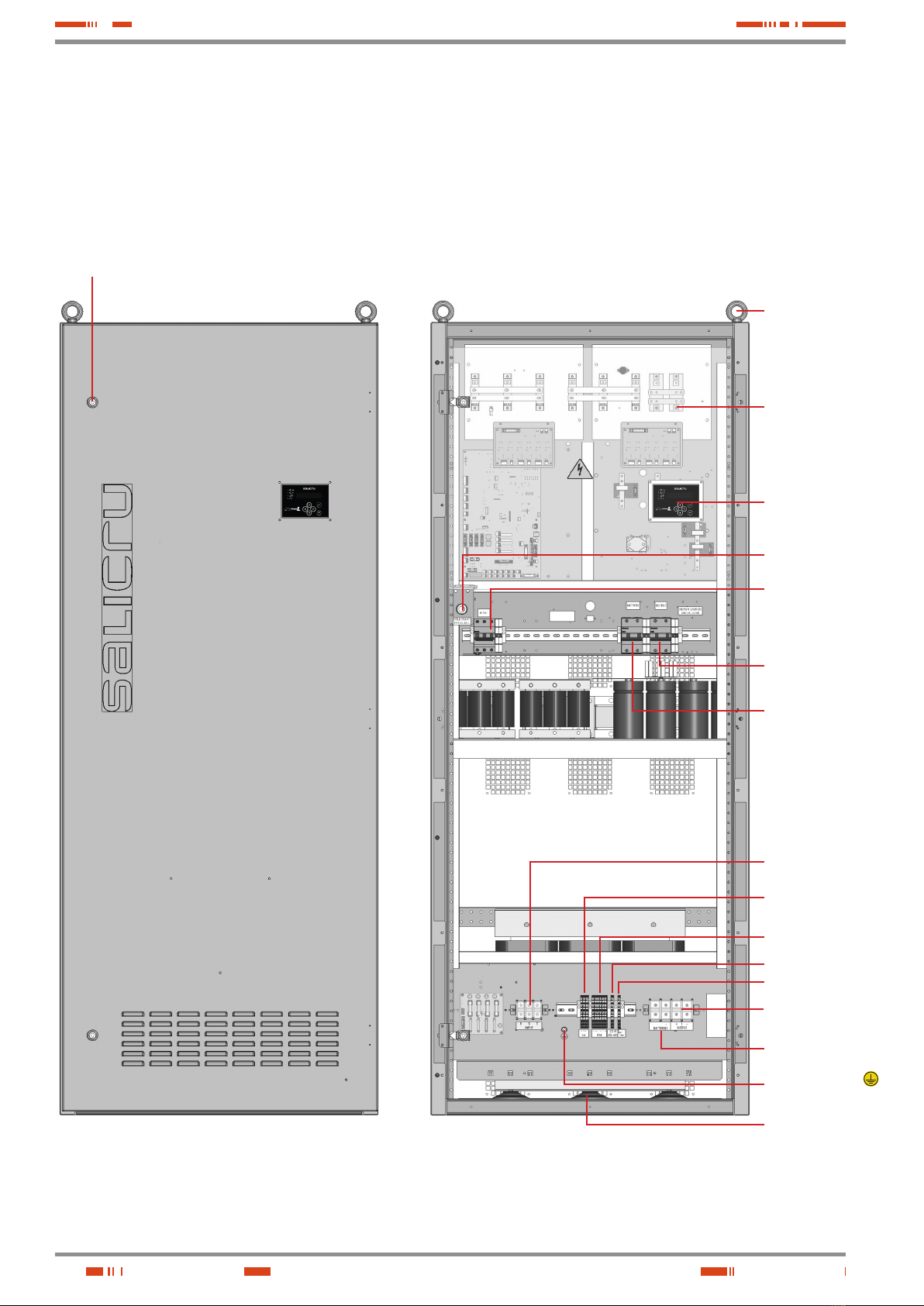
• The device is delivered properly labelled for correct identifi-
cation of each of its parts, which, together with the instruc-
tions described in this user manual, allows installation and
startup operations to be performed in a simple and organised
manner without any doubts whatsoever.
Finally, once the device is installed and operating, it is recom-
mended to keep the documentation pendrive in a safe and
easy-to-access location for future reference.
• If a system differs from that shown in the figures in Chapter
4 due to implementing or excluding elements or parts and/or
amending the technical specifications, additional explanatory
annexes will be published if considered appropriate or nec-
essary. These will usually be printed on paper.
• The following terms are used interchangeably in the docu-
ment to refer to:
‘DC Power-L 12-pulse, device, charger-rectifier,
system, DC power system or unit’.- DC power supply
device.
Depending on the context of the term, it can interchange-
ably refer to the charger rectifier assembly itself or to the
device with batteries, regardless of whether they are all
contained in the same cabinet.
‘Batteries or accumulators’ - Bank or set of elements
that stores the flow of electrons by electrochemical
means.
‘T.S.S.’ - Technical Service and Support.
‘User or customer’ - These are used interchangeably
and by extension to refer to the installer and/or operator
who carries out the corresponding actions, with the same
person possibly being responsible for carrying out the re-
spective actions when acting on behalf, or in representa-
tion, of the above.
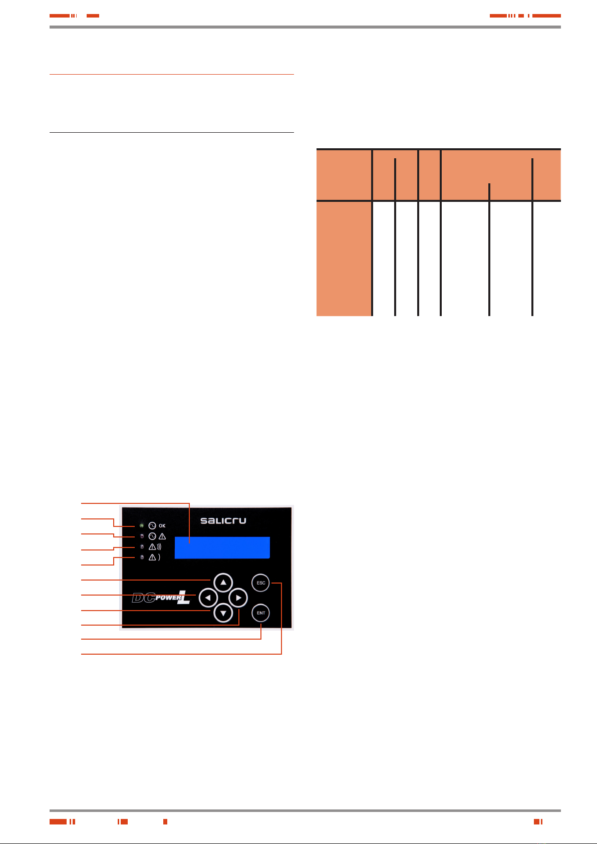
2.1.1. Conventions and symbols used.
Some symbols may be used and appear on the device, batteries
and/or in the context of the user manual.
For more information, see Section 1.1.1 of the ‘Safety Instruc-
tions’ document EK266*08.