All contents current at time of publication.
SALTO Systems S.L. reserves the right to change availability of any
item in this catalog, its design, construction, and/or materials.
©
2017 SALTO Systems S.L.
224901-ED2.- 07/07/2017
XS4 Controller
Installation guide
XS4 Controller
READER 1
A
B
TAMPER
IN1
IN2
IN3
IN4
IN5
IN6
READER 2
RL1
RL2
RL3
RL4
C
NC
NO
C
NC
NO
C
NC
NO
C
NC
NO
BUS485
Ethernet
10Base-T
100Base-TX
ON
12V
DC
Input
+
A
B
-
12V
DC
Output (1A)
Power Input: 12V
DC
-1A
GND
GND
+
-
+
-
+
-
+
-
+
-
+
-
+
-
A
B
+
-
Model:
CU42xx
2
1
3
4
5
6
7
1
9
8
10
11
12
READER 1
A
B
TAMPER
IN1
IN2
IN3
IN4
IN5
IN6
READER 2
RL1
RL2
RL3
RL4
C
NC
NO
C
NC
NO
C
NC
NO
C
NC
NO
BUS485
Ethernet
10Base-T
100Base-TX
ON
12V
DC
Input
+
A
B
-
12V
DC
Output (1A)
Power Input: 12V
DC
-1A
GND
GND
+
-
+
-
+
-
+
-
+
-
+
-
+
-
A
B
+
-
Model:
CU42xx
2
1
3
4
5
6
7
1
9
8
10
11
12
READER 1
A
B
TAMPER
IN1
IN2
IN3
IN4
IN5
IN6
READER 2
RL1
RL2
RL3
RL4
C
NC
NO
C
NC
NO
C
NC
NO
C
NC
NO
BUS485
Ethernet
10Base-T
100Base-TX
ON
12V
DC
Input
+
A
B
-
12V
DC
Output (1A)
Power Input: 12V
DC
-1A
GND
GND
+
-
+
-
+
-
+
-
+
-
+
-
+
-
A
B
+
-
Model:
CU42xx
2
1
3
4
5
6
7
1
9
8
10
11
12
12
1
10
11
2
3
4
5
6
7
8
9
E
Eng
F
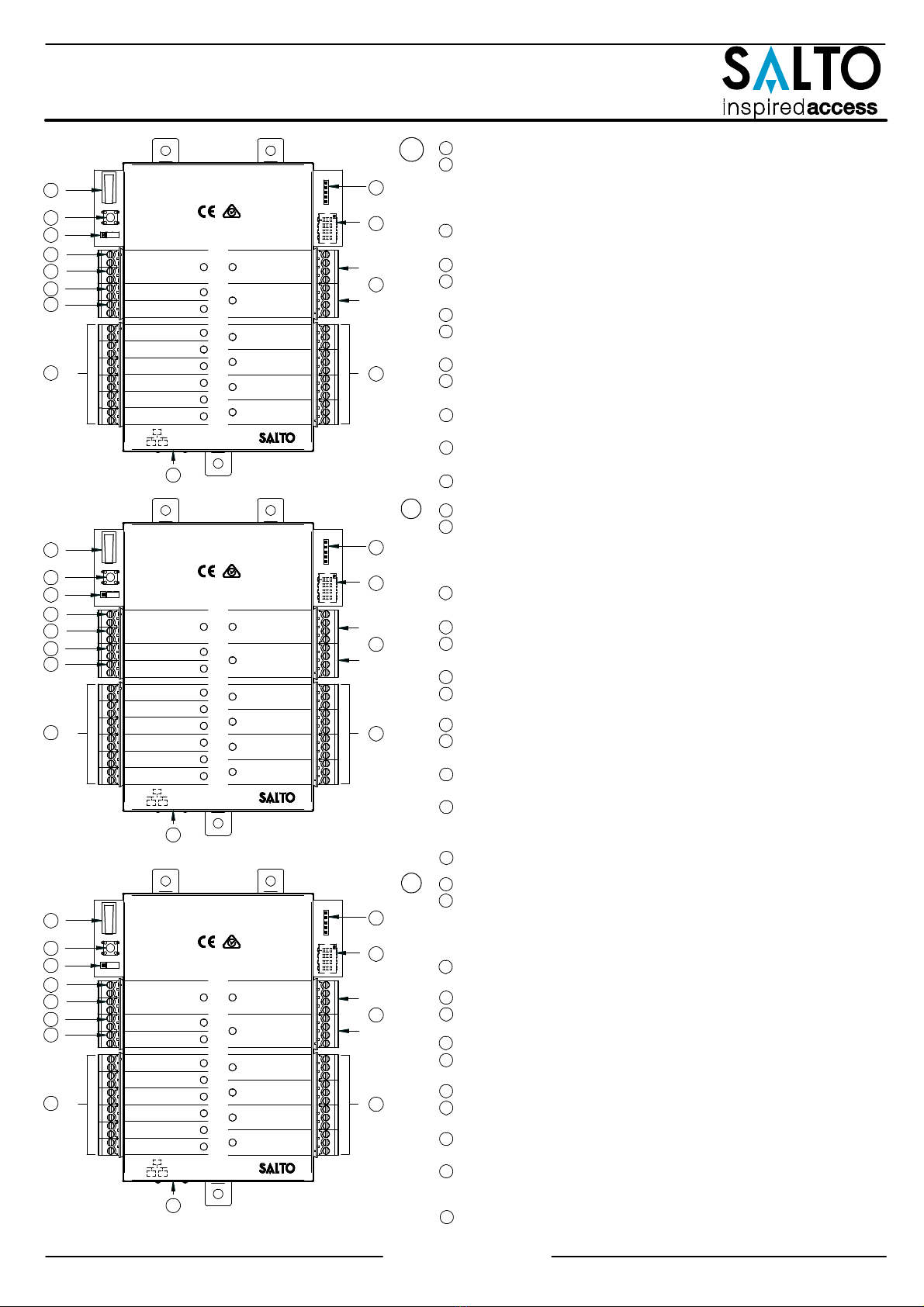
Tamper switch
is connected in parallel with tamper input.
Clear button
must be pushed (not more than 5 seconds) if the
configuration has been changed, (i.e. reader added, connected by
Ethernet, device connected by BUS485) and the tamper alarm must be
activated by removing the tamper switch connector.
BUS RS485 Terminal resistor
must be in the ON position when the CU is
connected at the end of the BUS.
Power input.
Power output:
this output is directly connected to the power input port
protected by a 1A fuse.
BUS485.
Inputs
: installer must identify the bridge cable needed depending on
the input configuration.
PPD Connection.
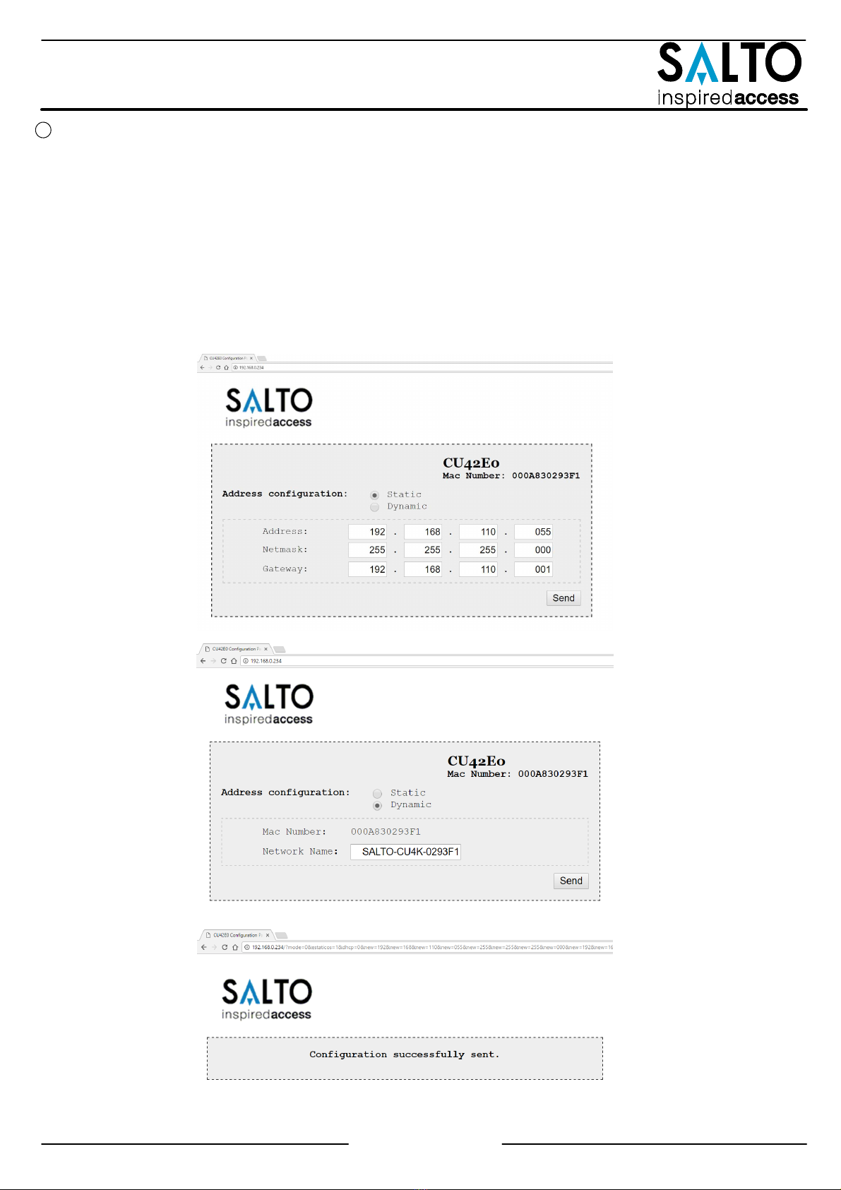
Address configure (Only CU4200)
All connected CU addresses must be
different from each other.
Connection to readers:
check reader installation manual to see
recommended cable, connections and max. distances.
Relay connections:
please take into account the max. load restrictions
(2A-30VDC). Use the provided varistor if an inductive load is used.
Ethernet connection (only CU42E0).
Tamper switch,
conectado en paralelo a la entrada del tamper.
Clear button
ha de ser pulsado (menos de 5 segundos), si se cambia la
configuración: lector añadido, conectado por Ethernet, dispositivo
conectado por BUS485 etc. Para ello, la alarma de tamper ha de estar
activada (quitar el conector del tamper input).
Resistor del terminal BUS RS485
requerido (posición ON) cuando la CU
está conectada al final del BUS.
Entrada de alimentación.
Salida alimentada:
esta salida se conecta directamente a la entrada
de alimentación protegida por un fusible de 1 A.
BUS485.
Entradas
: el instalador ha de identificar el cable para el puente
dependiendo de la configuración de la entrada.
Conexión para el PPD.
Configurador del direccionador (Solo CU4200)
Todos los
direccionamientos de las distintas CUs han de ser diferentes.
Conexión al lector.
Consultar el manual de instalación del lector para
ver el tipo de cable recomendado, conexionado y distancias máximas.
Conexión al Relé:
Tener en cuenta las restricciones de las cargas
máximas (2ª-30VDC). Utilizar el varistor suministrado si la carga es
inductiva.
Puerto Ethernet (solo CU42E0).
12
1
10
11
2
3
4
5
6
7
8
9
Contacteur anti subotage
monté en parallèle avec l’entrée anti sabotaje.
Bouton Clear
doit être appuyé (pendant au moins 5 secondes) lorsque la
configuration est modifée (ex: ajout d’un lecteur, connexion d’un cordon
Ethernet, ajout d’un dispositive sur le BUS485) l’alarmeanti sabotage doit
être active en enlevant le cavalier du bornier.
La résistance de fin de bus RS485
est nécessaire (position ON) lorsque la CU
est positionn’ee à l’extrémité du bus.
Puissance d’entrée.
Puissance de sortie:
Cette sortie est reliéedirectement au port d’ entrée de
l’alimentation protégee par un fusible de 1 A.
BUS485.
Inputs:
L’installateur doit identifier le cable necessaire en function de la
configuration d’entrée.
Connexion pour le PPD.
Configuration de l’adresses (Uniquement pour CU4200)
Les addresses des
CU connectées au même BUS doivent être toutes différentes.
Connexion des lecteurs:
Consultez le manuel d’installation du lecteur afin
de voir les câbles recommandés, les connexions et les distances maximales.
Connexion des relais:
S’il vous plaît prendre en compte les restrictions de
charge max. (2ª-30VDC). Utilisez les varistances fournis si une charge
inductive est utilisée (24v AC/DC Max).
Connexion Ethernet (uniquement CU42E0).
12
1
10
11
2
3
4
5
6
7
8
9
2/20