Salutron SRTPro User manual

30
Surface Roughness Tester
SRTPro
Instruction manual


CONTENT
1ROUGHNESS TESTER OVERVIEW .......................................................................................................3
1.1 FEATURES OF INSTRUMENT...........................................................................................................................3
1.2 MEASUREMENT PRINCIPLE............................................................................................................................3
1.3 NAME OF EACH PART...................................................................................................................................4
1.4 BUTTONS DEFINE ..........................................................................................................................................6
1.5 BATTERY CHARGING.....................................................................................................................................6
1.6 CONNECTION METHOD OF SENSOR AND MAIN UNIT ...................................................................................7
2MEASURING OPERATION .......................................................................................................................9
2.1 PREPARATION FOR MEASUREMENT...............................................................................................9
2.2 TURNING ON/OFF...................................................................................................................................9
2.3 STYLUS POSITION ...............................................................................................................................10
2.4 START MEASUREMENT......................................................................................................................10
2.5 MEASUREMENT RESULT DISPLAY .................................................................................................11
2.6 PRINT MEASUREMENT RESULTS....................................................................................................11
2.7 STORAGE MEASUREMENT RESULTS.............................................................................................12
2.8 MEASURING PARAMETER SETTINGS............................................................................................12
2.9 STORAGE MANAGEMENT.................................................................................................................13
2.10 DATE SETTINGS.................................................................................................................................15
2.11 SOFTWARE INFORMATION...............................................................................................................15
2.12 PARAMETER CALIBRATION.............................................................................................................16
2.13 PRINT SETUP .........................................................................................................................................17
3OPTIONS AND USAGE ...........................................................................................................................18
3.1 ADJUSTABLE SUPPORT...............................................................................................................................18
3.2 MEASUREMENT STAND ...............................................................................................................................19
3.3 EXTENDING ROD ........................................................................................................................................19
3.4 STANDARD SENSOR....................................................................................................................................19
3.5 CURVED SURFACE SENSOR .........................................................................................................................20
4TECHNICAL PARAMETER AND FEATURES .....................................................................................22
4.1 TECHNICAL PARAMETER.............................................................................................................................22
4.2 MEASURING RANGE ..................................................................................................................................23
5GENERAL MAINTENANCE ....................................................................................................................23
5.1 SENSOR ......................................................................................................................................................23
5.2 MAIN UNIT ................................................................................................................................................23
5.3 BATTERY.....................................................................................................................................................23
5.4 STANDARD SAMPLE PLATE .......................................................................................................................24

5.5 TROUBLESHOOTING..................................................................................................................................24
6REFERENCES...........................................................................................................................................24
6.1 TERMS........................................................................................................................................................24
6.1.1 Terms ............................................................................................................................................................25
6.1.2 Traversing Length........................................................................................................................................25
6.2 PARAMETERS DEFINITIONS.......................................................................................................................26
6.3 RECOMMENDED TABLE OF THE SAMPLING LENGTH.................................................................................28

3
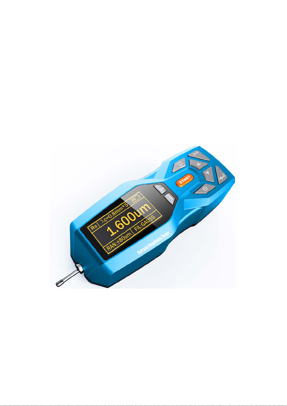
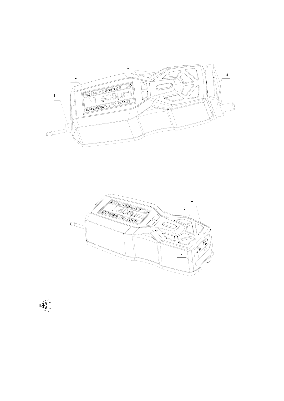
1 Roughness tester overview
The surfaces roughness tester is suitable for shop floor use and mobile measure to need of a
small handheld instrument, it operation simple, function overall, measure fast, accuracy stability,
take convenience. This tester applies to production site and can be used to measure surface
roughness of various machinery-processed parts. This tester is capable of evaluating surface
textures with a variety of parameters according to various national standards and international
standard. The measurement results are displayed digital/graphically on the OLED and can be
outputed to the printer.
1.1 Features
Electromechanical integration design, small size, light weight, easy to operation;
DSP chip control and data processing, high speed, low power consumption;
Large measurement range;
14 parameters: Ra、Rq、Rz、Rt、Rp、Rv、R3z、R3y、RzJIS、Rs、Rsk、Rku、Rsm、Rmr
128 × 64 OLED dot matrix display, digital or graphic highlight display; no viewing angle;
Display full information, intuitive and graphical displays all parameters;
Compatible with ISO, DIN, ANSI, JIS multiple national standards;
Built-in lithium-ion rechargeable battery and control circuit, high capacity, no memory effect;
There are remaining charge indicator, charging hint;
Tester has charging instructions, the operator can readily understand the level of charge
Can work more than 20 hours while the power is enough;
Large capacity data storage, can store 100 item of raw data and waveforms;
Real-time clock setting and display for easy data recording and storage;
With automatic sleep, automatic shutdown power-saving features;
Reliable circuit and software design of prevent the motor stuck;
Instrument can display a variety of information tips and instructions. For example Measurement
result display, the menu prompts and error messages;
Metal case design, rugged, compact, portable, high reliability;
Can connected to the computer and printer;
All parameters can be printed or print any of the parameters which set by the user;
Optional curved surface pickup sensor, holes sensors, measurement stand, Sheath of sensor,
extension rod, printer and analysis software;
1.2 Measurement principle
When measuring roughness of part surface, the pickup is placed on the surface of the part and
then tracing the surface at constant rate. The pickup acquires the surface roughness by the sharp
stylus in pickup. The roughness causes displacement of pickup which results in change of inductive
value of induction coils thus generate analogue signal which is in proportion to surface roughness at
output end of phase-sensitive rectifier. This signal enters data collection system after amplification
and level conversion. After that, those collected data are processed with digital filtering and
parameter calculation by DSP chip and the measuring result can be read on OLED, printed through
printer and communicated with PC.

4
1.3 Name of each part
Skid
Stylus
Protective Tube
Main Body Socket
Sensor
Sampling
Length Number Battery
indicator
Parameters
Range Filter Unit
Assess
Length
Display Interface

5
1. sensor 2. display 3. key area 4. adjustable support
5. USB charge 6. power switch 7. fixing hole
Power switch is a total power switch on the instrument.
Turned off when not in use for a long time.

6
1.4 Buttons define
Power key: Press and hold min. 2 seconds to switch on or off
Stylus position keys: For switching between stylus position display
Start key: Start the measurement
Parameter selection Key: Used to view various parameters
Record storage key/ print key: For storing and print the record results
Up Arrow key: To select items for the switch
Down arrow keys: Select the item for switching
Menu / Enter key: To enter the menu settings
Cancel / Exit key: Used to exit the menu and unset
1.5 Battery Charging
When battery voltage is too low (battery voltage symbol displays on the screen), the
device should be charged as soon as possible. Use USB port of the instrument for charging. You can
use the power adapter for charging or the computer's USB port for charging. Please notice that by
using of the other power adapter, the output voltage should be 5V DC, the current should be greater
than 800mA.
During charging the instrument displays animation and stops after the battery is full. Charging
time is about 2.5 hours.
This instrument adopts lithium ion chargeable battery without memory effect and charging can
be fulfilled at any time without affecting normal operation of the instrument.
When
charging, ensure that the instrument side of the power
switch is in the ON position

7
1.6 Connection of sensor and main unit
main body
protective
tube
protective
tube
main body sensor socket
Installation and Removing of sensor
For installation, hold the main body of sensor with hand, push it into connection adapter at the
bottom of the instrument as shown in Figure and then slightly pushed it to the end of the sheath. To
remove, hold the main body of pickup or the root of protective sheath with hand and slowly pull it
out.
1、Stylus of pickup is key part of this tester and great attention. should be paid to it.
2、During installation and unloading, the stylus should not be touched in order.
to avoid damage and affecting measurement.
3、Connection of sensor should be reliable during installation.

8

9
Battery
indicator
Number
Sampling
Length
Assess
Length
UnitFilter
Range
2 Measuring Operation
2.1 Preparation for Measurement
Switch-on to check if battery voltage is normal;
Clear the surface of part to be measured;
Place the instrument correctly, stably and reliably on the surface to be measured;
Trace of the pickup must be vertical to the direction of process line of the measured surface.
: Correct and standard operation is the premise for accurate measurement
result, please make sure to follow it.
2.2 Turning On/Off
Press the key to hold 2 seconds
after the instrument will automatically boot,
boot will display equipment type, name and
manufacturer information, and then enter
the basic measurement status main display
interface, as shown.
Introductions:
1. The next boot will be displayed when the last shutdown set content
2. Startup and shutdown, press and hold the key for about 2 seconds to open the instrument will
perform the appropriate action
3. Long time not to use, the instrument should be on the side of the power switch turned off
4. Start measuring sensor is installed, please refer to the stylus position, try to adjust the stylus
cursor position to the best position "0"

10
2.3 Stylus Position
First, use the stylus position to determine the
location of the sensor. The stylus as measured in
the middle position.
In the main interface mode, press the stylus
position key switches stylus position
display screen and the main display screen.
2.4 Start measurement
In the main interface mode, press the Start button to start measuring
Testing...
ESC:stop
ESC:stop
Motor Detect...

11
2.5 Measurement result display
After the measurement, can be observed in Figure shows the results of all measurements.
10.3%
6.5%
5.1%
4.1%
100%
95%
80%
75%
100%
C(Rt)
100%
Rmr0
Rmr
C(Rt)
C(Rt) Rmr 0Rmr 100%
C(Rt) 100%
25%
30%
35%
40%
4.1%
5.1%
6.5%
10.3%
10.3%
6.5%
5.1%
4.1%
20%
15%
10%
5%
100%
C(Rt)
100%
Rmr0
Rmr
C(Rt)
R3z= 6.168
μm
Rv= 3.012
μm
Rp= 3.298
μm
Rt= 6.236
μm
Roughness
Rsk=
-0.11
RzJIS= 5.08
μm
R3y= 6.238
μm
Rku= 0.96
Rsm= 0.08mm
Rq= 1.768
μ
m
Rz= 3.016
μm
Ra= 1.598
μ
m
Roughness
2.6 Print measurement results
The instrument can be connected to the printer.
The measurement results will be printed.
After measurement, Press key to
display the measurement results.
Press key to print the measured data
to a serial printer. At this point, key is
a print key to use.
The instrument can be used according to the
actual requirements of arbitrary parameters
choose to print or print all the parameters, how
to set the parameters, refer to "Print Settings."
C(Rt) Rmr
10% 7.2%
20% 41.8%
30% 49.8%
40% 52.1%
50% 54.2%
60% 55.9%
70% 58.6%
80% 66.5%
90% 96.6%
100%C(Rt)
0Rmr
100%
************************
Surface Roughness Tester
************************
2013.04.18 11:05:08
Ln = 0.8mmX5
Range = 40um
Filter = GAUSS
Ra = 1.598um
Rz = 4.275um
Rq = 1.691um
Rt = 5.113um
Rp = 1.966um
Rv = 2.309um
Rs = 0.08mm
R3z = 3.853um
R3y = 4.059um
RzJIS = 3.901um
Rsk = -0.16
Rku = 1.18
Rsm = 0.08mm
Roughness
Ra= 1.598
μ
m
Rz= 4.275
μm
Rq= 1691
μ
m
C(Rt) Rmr 0Rmr 100%
C(Rt) 100%
5%
10%
15%
20%
4.1%
5.1%
6.5%
10.3%

12
2.7 Storage measurement results
In the main display interface mode, press the key to save the measurement results stored in
the instrument memory. Instrument built-in large capacity memory, can store 100 groups of raw
data and waveform data.
Data storage recording date and time the file name automatically generated according to the last
data record is always stored the most recent recording time, the last data record stored recording
record number will be 001.
Saving...
2.8 Measuring parameter Settings
In the basic measurement mode, press the key to enter the menu operation state, press the
keys to select "Preferences" function, then press the key to enter the
parameter setting mode. In the parameter setting mode, you can modify all the measurement
conditions.
LANGUAGE ENG
UNIT
μ
m
DISPLAY Ra
FILTER GAUSS
Parameter
λ
c
0.8mm
λc 5
RANGE
±40μ
3.Date
2.Recoder
1.Parameter
Menu
Content
ENG CHS
μmμin
;;;
±20;±40;±80μ
1-5
0.25 ;0.8 ;

13
2.9 Storage Management
In the basic measurement mode, press the key to enter the menu operation state, Press the
keys to select "Recoder" function, Press the key to enter management
projects.
2.
Format
1.
View
Recoder
Menu
3.Date
2.Recoder
1.Parameter
Recoder management by the two project components, 1 view 2 format.
Selected item and press the Enter key to enter.
2.9.1 View Record
006 2013.05.06 08:08
007 2013.05.06 08:06
009 2013.05.06 08:02
008 2013.05.06 08:05
010 2013.05.01 08:08005 2013.05.08 09:01
003 2013.05.08 09:05
004 2013.05.08 09:03
002 2013.05.08 09:07
001 2013.05.08 09:08
Recoder Recoder
Page Up
Page Down
Item Down
Item Up
Select the appropriate records, press View log content
In view records content, data can be printed according to the specified printer, operate
the following figure.

14
Rz= 3.016
μm
Rq= 1.768
μ
m
Rsm= 0.08mm
Rku= 0.96
R3y= 6.238
μm
RzJIS= 5.08
μm
Rsk=
-0.11
0.8mmx5
±
40
μ
m GAUSS
Rt= 6.236
μm
Rp= 3.298
μm
Rv= 3.012
μm
R3z= 6.168
μm
C(Rt) Rmr 0Rmr 100%
C(Rt) 100%
5%
10%
15%
20%
4.1%
5.1%
6.5%
10.3%
10.3%
6.5%
5.1%
4.1%
40%
35%
30%
25%
100%
C(Rt)
100%
Rmr0
Rmr
C(Rt)
C(Rt) Rmr 0Rmr 100%
C(Rt) 100%
75%
80%
95%
100%
4.1%
5.1%
6.5%
10.3%
************************
Surface Roughness Tester
************************
2013.04.18 11:05:08
Ln = 0.8mmX5
Range = 40um
Filter = GAUSS
Ra = 1.598um
Rz = 4.275um
Rq = 1.691um
Rt = 5.113um
Rp = 1.966um
Rv = 2.309um
Rs = 0.08mm
R3z = 3.853um
R3y = 4.059um
RzJIS = 3.901um
Rsk = -0.16
Rku = 1.18
Rsm = 0.08mm
100%Rmr0
100%C(Rt)
C(Rt) Rmr
10% 7.2%
20% 41.8%
30% 49.8%
40% 52.1%
50% 54.2%
60% 55.9%
70% 58.6%
80% 66.5%
90% 96.6%
Print
2013.05.06 08:08:16
Ra= 1.598
μ
m

15
2.9.2 Format
Data format is the deletion of data records, once formatted and all data will be cleared. In the
data before formatting instrument has confirmation prompt information, user data will not be
restored after confirmation.
1.View
2.Format
Recoder
Do not Shutdown Power
Format...
Farmat
Are you sure?
2.10 Date Settings
Built-in real time clock calendar instrument used to record information about the test of time to adjust date and
time as follows
1.Parameter
2.Recoder
3.Date
Menu
Up: + Down:-
2013.05.08
Date
09:01:18
:Change :Back
2.11 Software Information
Instruments software and hardware information can help users easily upgrade and maintain the product, unique
serial number of the instrument software information items are displayed.
4.Calibrate SN:K00113061718
RoughnessTester
Version V1.0
About
Menu
5.Print
6.About

16
2.12 Parameter calibration
Before measuring instrument, usually required
calibration use standard calibration Block. The
instrument is configured with a standard
calibration block, before measurement,
instruments to test the block. Under normal
circumstances, when the measured value and the
block value of the difference in the acceptable
range, the measurement value is valid, can be
measured directly.
If the measured value and the block value of the
difference is greater than a accuracy error range of
the instrument, or the user require high accuracy,
can be used to correct the indication calibration
function and improve measurement accuracy.
Showing the value of the calibration procedure as
shown.
Illustration is based on a model calibrated 1.63µm
steps to calibrate the model for the actual
calibration of the nominal value of the set value.
1、 Under normal circumstances, the instrument in the factory have been rigorously tested,
showing error is much less than ± 10%, in this case, the user is not showing the value
of the calibration frequently used functions.
2、 After setting the calibration value, you must press the key for a full
measurement, instrument calibration to be valid.
3、 New parameters after calibration must be carried out once a complete measurement and
press the key is stored in the instrument.
4、 Press "ESC" key to return the menu without saving calibration results.
Ra= 1.63μm
ESC: Stop
Calibrate..
.
Ra= 1.63μm
Ra= 1.51μm
Calibrate
6.About
5.Print
4.Calibrate
Menu
Calibrate
Calibrate
Menu
4.Calibrate
5.Print
6.About

17
2.13 Print setup
The instrument can be used according to the actual requirements of any parameter selection Print or
Print All, the steps shown in Figure.
6.About
5.Print
4.Calibrate
Menu
Print
6.About
5.Print
4.Calibrate
Menu
4.Rt OK
2.Rz OK
14.Rmr
3.Rq OK
2.Rz OK
1.Ra OK
Print

18
3 Options and Usage
3.1 Adjustable support
When measured surface of part is smaller than the bottom surface of the instrument, sheath of
pickup and adjustable supporter of instrument options can be used for auxiliary support to complete
the measurement (as shown in Figure).
Adjustable
Support
1.the value L above shall not be shorter than driving stroke of this measurement to prevent
pickup from dropping out of part during measurement.
2. Locking of adjustable supporter shall be reliable
Table of contents
Other Salutron Test Equipment manuals