Samba Model Prestige 2PK User manual

Congratulations for choosing the right model! Your new Prestige 2PK.
The model is a handmade product, carefully packed for your convenience.
Please check that all items ordered are included and not damaged during transportation.
A basic model includes:
3 wing sections (including GFK horns if no IDS is ordered)
1 fuselage with nose cone
1 rudder
1 Elevator
2 carbon joiner 6 degrees
2 pcs clevis couplers
Wire harness fuse with plastic holders for tip connection
4 plastic servo covers
2+2 screws for Elevator and Wing
Wing and fuse bag
Additionally you can order:
ballast set
8 degree joiners (6 degree standard)
The model can be ordered fully assembled
or partly
To complete a model you will need:
2 pcs +/-20g metal geared servos for the flaps.
4 pcs 9-12g metal geared servos for fuse and tips.
IDS from Servorahmen.de or alternately 8 clevises and 2mm threaded rods for
the wings
Motor, regulator and battery
Spinner and propeller in 30mm or 32mm according to your order
a high quality receiver
epoxy to glue in the servos and thin cyano (CA) to secure clevises
strong clear tape (8-12mm wide) to join the wings and rudder to the fuselage
Assembling the wing:
Sand the surface of the servos and the servo trays where the servos will be glued
Connect the servos and the fuse harness to the respective channels on the
receiver. Check that the aileron servo arms are set 90 degrees on the servo and
that the transmitter also is set to neutral. Check that the flap servo arms are set
identically to approximately 20 degrees (measured from the 90°-angle) towards
the flap. The transmitter should later be set to an offset so that the flap servo
arms are 90 degrees on the servos. With full butterfly the servo arms on the flaps
are almost straight towards the flap. This ensures full deflection of the flaps for
butterfly brake
Check again the servo settings and also set the offset of the flap servos. Check
also that the servos move the right way
Mark where the servos will be glued in place by a pencil in the servo trays. Use a
Dremel tool with grinder to open up the pushrod hole and the aileron/flap horn.
Ensure that the servo arm is aligned (straight line) to the line defined by the hole
in the subspar and the aileron/flap horn
Now are available IDS for
IDS Typ MKS 6110 Foam Mono
IDS Typ KST 08 Foam Mono (KST X08 H)
IDS Typ MKS 75K Foam
IDS Typ KST X10 Mini Foam
IDS Typ MKS 6130 Mini Foam
IDS Typ JRDS 181, JRDS 189 Foam

Distance flaps to pin is 3mm
Distance aileron to pin is 0,5mm
Glue the aileron and flap horns. When using the IDS from servorahmen.de the
horns will be glued flush with the upper surface for both aileron and flaps. Mount
the pushrod to the horn to ensure easy positioning while glue is settling.
When not ordering the IDS there is fiberglass horns provided in the set.
Glue the servos/IDS frame in using epoxy. If the epoxy is thin it is possible to add
some thixotropy agent. It is also possible to use Cyano glue in small amounts
Install the threads and clevises whilst the servo arms are set 90 degrees on the
servos and the ailerons / flaps are set in neutral position. When using
thread/clevis secure the thread to the clevis with extra thin CA as this is a place
with some slop. Check also thoroughly the clevis pins going into the horns and
servo arms. There are clevises that can be poorly made in this special detail. Use
the inner most hole on the servoarms possible to ensure full power of the servo
yet providing full throw.
On ailerons it is possible to use a simple bent 1,5mm pushrod with the
servorahmen setup.

Install and glue with Cyano the connector holders in tips and midsection. It can
also be glued with epoxy or polyurethane glue. We do not recommend heat glue.
Start with one side and the other side as the tip are inserted. This ensures perfect
fit and connection each time. There is a small wire connector supplied for each
tip/servo bay. Be careful not getting Cyano into the connector metal parts.
It is recommended to install clear tape on the ends of the wings. This will prevent
the paint being ripped off when the tape is applied / removed every time you go
flying
Adjust the aileron throw according to the settings sheet below.
Meassure the throws from neutral on the inner part of the surfaces
Adjust the aileron throw on flaps
Adjust the crow brake flaps to as much as possible (70-85 degrees is good)
Adjust the crowbrake on ailerons to 1mm up (no bending while brakes applied)
Camber for thermal is +1-5mm measured on flaps and equal along the whole
trailing edge
Camber/reflex for distance/speed is -1 and -2 mm
Snap flap (elevator – flap mix) can be used up to 5mm on full elevator throw
Cut the servo covers so the fit and secure them with tape
IDS installation on youtube
Part 1 https://www.youtube.com/watch?v=f1HJjbIv5uE
Part 2 https://www.youtube.com/watch?v=GtK9itGYJsM
Tip servo installation on youtube by Flightcomp: https://youtu.be/j8pwiXLxQBM
Midsection installation on youtube by Flightcomp: https://youtu.be/-UN7GagaiYA
Aileron and flap servo details – below: Contact holder arrangement glued in

Assembling the fuselage:
After installation the nose cone back part can be shortened by up to 105mm to
adjust the CG. All depending on motor/propeller/ESC/battery used.
Use a Dremel tool to open the servo bay where the servo horn is coming down to
the pushrod. Also make holes for servo wires and wing harness. Make the holes so
that wires does not go into the bottom of the fuse. The bottom of the fuse needs
the space for the ballast rod
Install the “fuse to wing”-harness in the fuselage. Roughen the green connector
and fuselage fitting before you glue it
Install the receiver in the slot under the wing. Drill holes backwards so that the
antenna comes out without making a sharp bend. The antennas (2.4) should
come out behind the wing on each side (min 2-4cm behind). A range test will
show that your installation is correct. A third (or the second) antenna can be
under slightly under the wing and straight down but careful on ballast position. Be
also very careful on not drilling into the pushrods.
Antenna holes / guidance tubes
Cutting holes in fuse before assembly
Cut in fuse for receiver wires

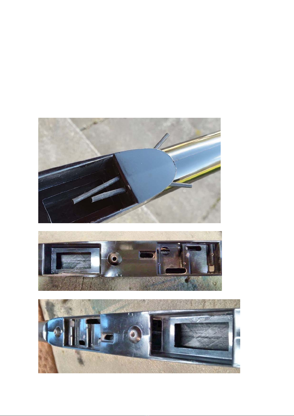
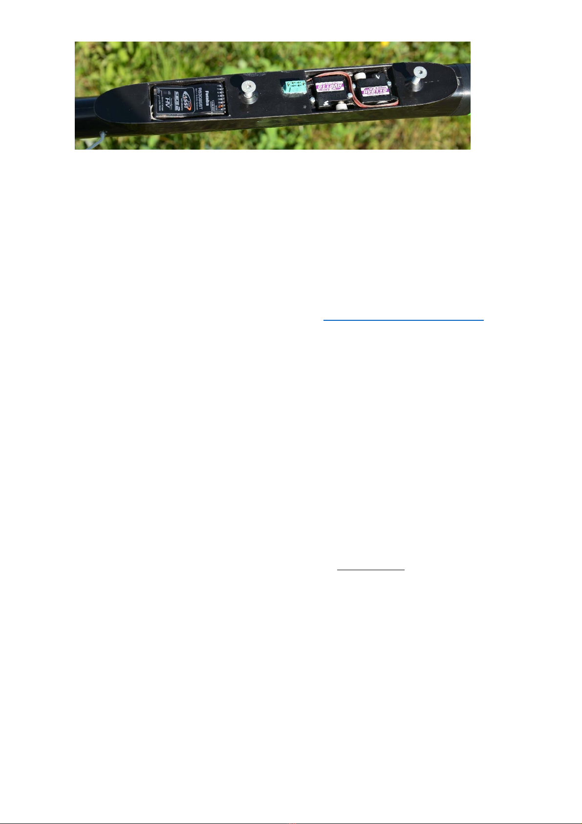
Servos and receiver installed in fuse
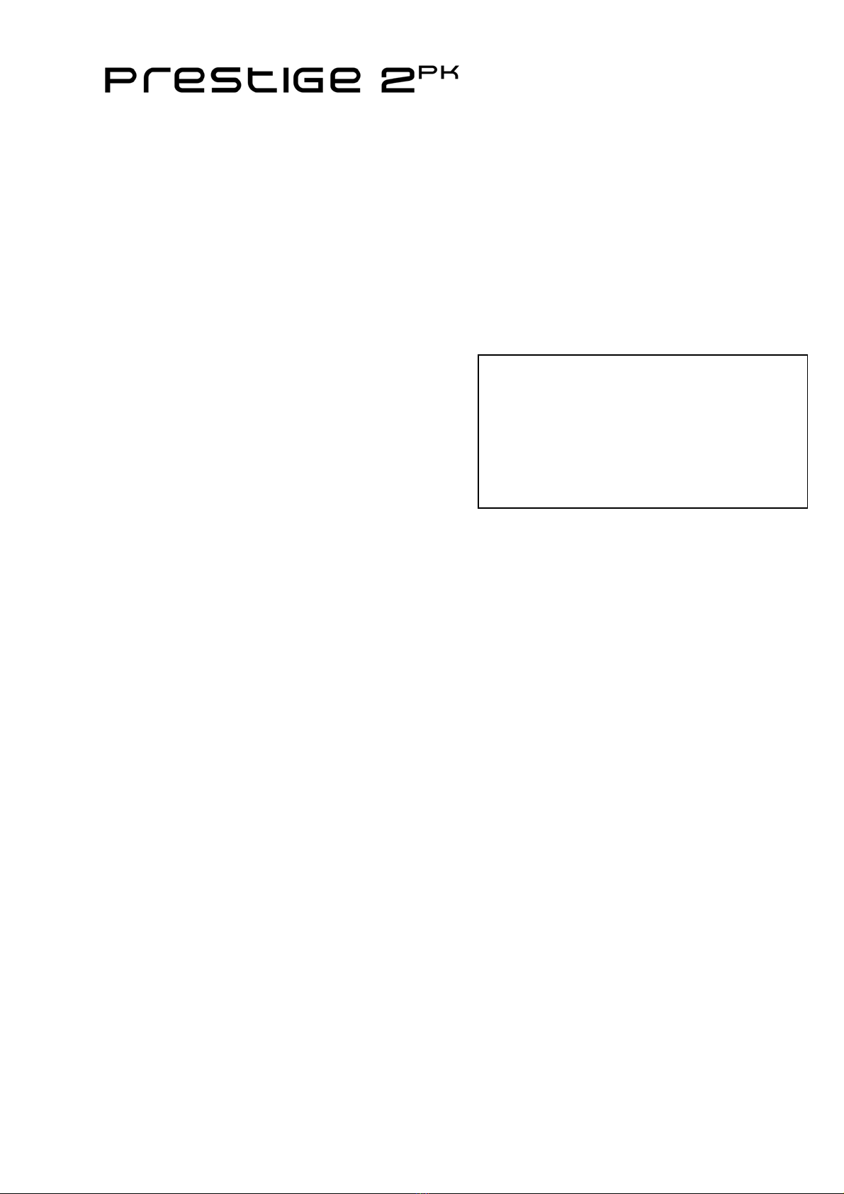
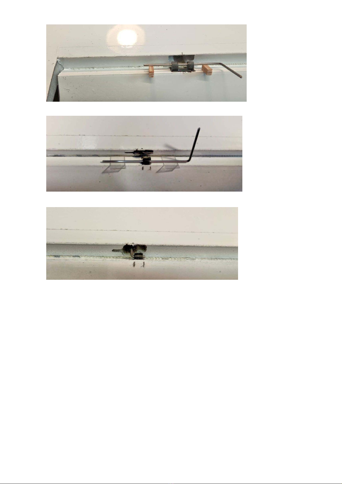
Mount elevator and rudder and secure in neutral with some tape. Shorten the rod
for correct length by marking the total length to servo horn with a pen and then
pull forward thru opening for cutting. The coupler can be glued to the carbon rod
with Cyano and for safety pinch the coupler with a plier to ensure tight fit. Check
the connection thoroughly
Adjust the elevator so that it is in neutral checking top and bottom airfoil (trailing
edge 24mm from fuse). Full throw is 15mm up and 17mm down. At full crow the
elevator goes down to approximately 11mm depending on crow settings for wing.
It is good to ensure more down throw (+6mm) possible after crow brake is set
Adjust rudder throw to 30mm +/-
Using excess of of 40mm might slow down the model instead of yaw motion
Fuse installation on youtube by Flightcomp: https://youtu.be/xG_r3nwUsmw
Assembling the model:
Attach the rudder to the fuse and insert the screw provided to secure the rudder.
Secure with a tiny piece of tape round the front part. Carefully push the ball link
in place and check that they move freely. Pinch the plastic with a plier to free
them up if they are tight. The ball link can be removed by using a flat screwdriver
clicking it off again.
Screw on the elevator and be sure the pushrod pin is inserted before.
Screw on midsection wing and plug in the tips with the included joiners inserted
first in the tips completely inserted.
Attach the tips with clear tape to secure at top and around leading edge.
Check and adjust the CG (center of gravity). A suitable CG to start off is 110mm
for all conditions and 112mm from leading edge in calm conditions
Check range according to transmitter specifications.
If you can not get the necessary range you need to:
1) Check antenna locations
2) Try another transmitter
3) Try another receiver
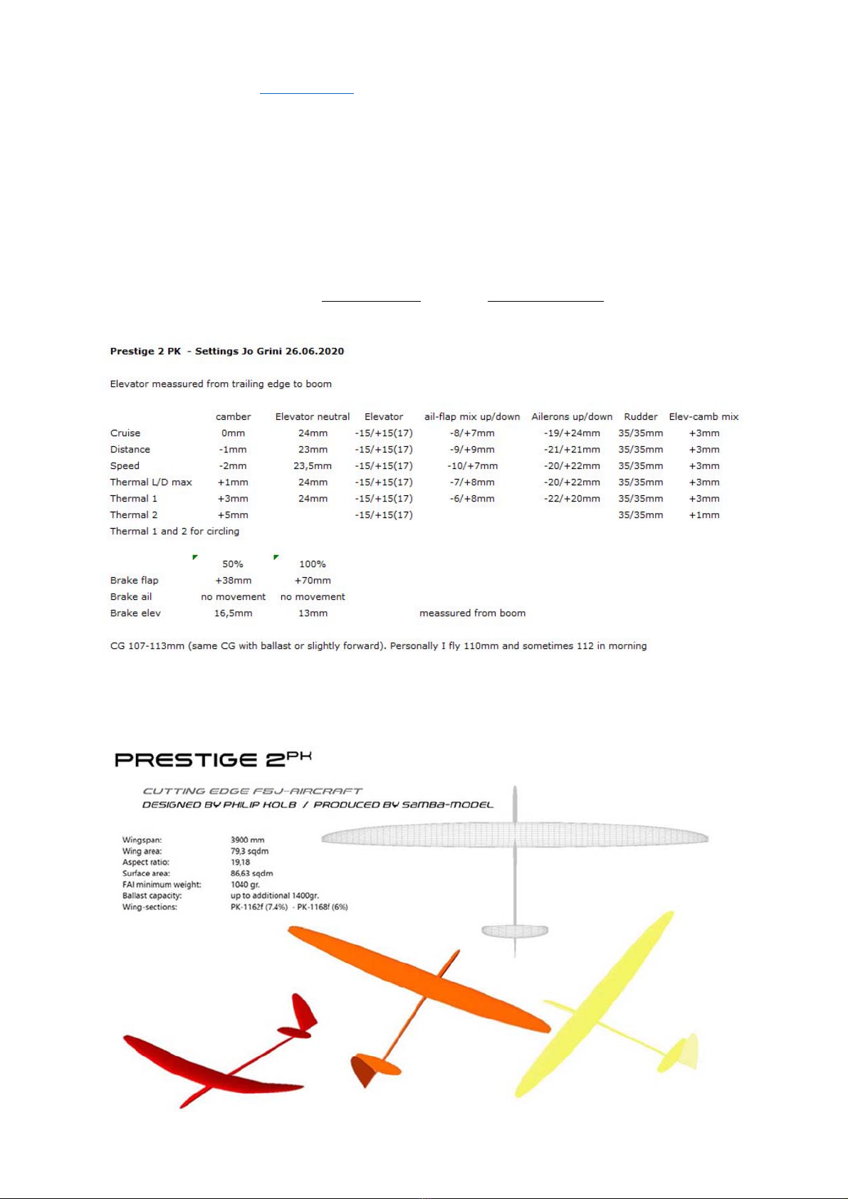
Settings:
All the latest detailed settings can be found on www.F3J.com.
These are settings from some of the world’s best pilots.
You will find these setting a very good starting point.
Wings cannot stay in the sun without wing covers. Covers prevent excessive heating of
the model as there could appear some deformations of model parts when model is
overheated, or the surface could get distortions. If the reflex painted parts are not
protected against the sun, the reflex effect will fade much earlier even if there is used
layer of paint with UV filter.
Prestige 2PK specifications are without any guarantee for structural stiffness. Sudden
changes in the deflection of the controls at high speeds are also prohibited.
The model is intended for F5J competition flying and not for aerobatics.
After harder landings it is necessary to check the joiner and look for cracks as it could
cause failure of complete model in the next flights.

We hope you will be satisfied with your new model. If you have any questions be sure to
look at our webpages www.f3j.com . Additional info about the setup and detailed pictures
can be found there.
Important notice for pilots with Prestige 2PK F3J version
You need to stick the rudder to the fuselage with epoxy. Fixed connection.
Roughen both glued surfaces before gluing. Care must be taken not to glue the rudder
pushrod. Do not put any glue in the vicinity of the rod.
The Prestige 2PK is originally designed as an F5J model. The connection between the
rudder and the fuselage is not strong enough for the F3J start.
Regards
Samba Model
This manual suits for next models
2
Table of contents
Other Samba Model Toy manuals
Popular Toy manuals by other brands

Eduard
Eduard Typhoon Mk.Ib landing flaps manual

Troy Built Models
Troy Built Models F86D DOG SABRE user manual

LEGO
LEGO creator 10214 Assembly guide

Hasbro Gaming
Hasbro Gaming Chow Crown quick start guide

Flying Gadgets
Flying Gadgets F-series 2.4G instruction manual

Hasbro
Hasbro GIJOE VS Cobra ForestFox Frostbite manual