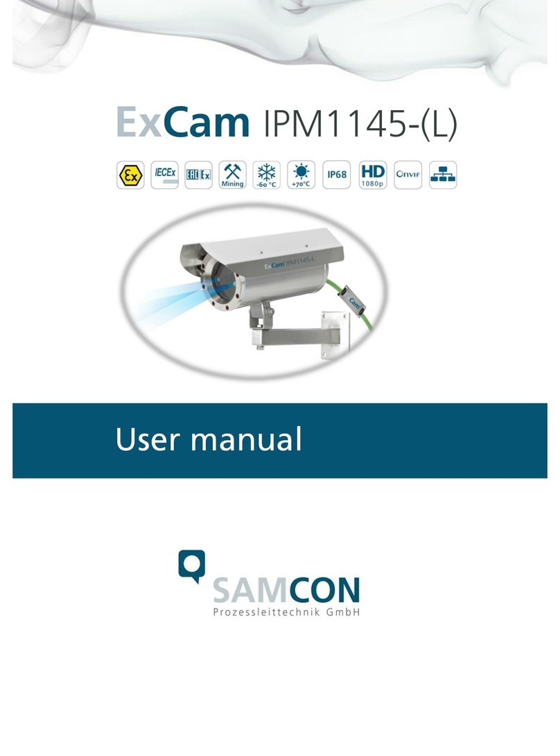
Samcon RoughCam IPM1145 User manual

RoughCam IPM1145-(L)
User manual

Doc.-ID: 180516-PT10BA-ES-RoughCam IPM1145-(L)_en_rev.01.docx, page 2 of 40
Content
1Introduction ..............................................................................................................5
2Technical Data..........................................................................................................6
2.1 Electrical parameters of the camera module.......................................................6
2.1.1 RoughCam IPM1145-(L) (PoE+) (Camera and Heater)............................................................6
2.1.2 RoughCam IPM1145 .................................................................................................................6
2.1.3 RoughCam IPM1145-L..............................................................................................................6
2.2 Electrical parameters of the PTC heat load circuit (optional)...............................6
2.3 Connection cable SKD01-T.................................................................................7
2.4 Power Supply cable (optional).............................................................................8
2.5 Technical specification of the camera modules...................................................9
2.5.1 Axis M1145................................................................................................................................9
2.5.2 Axis M1145-L.............................................................................................................................9
2.6 IR-LED Illumination .............................................................................................9
2.6.1 Axis M1145................................................................................................................................9
2.6.2 Axis M1145-L.............................................................................................................................9
2.7 Temperature range (MTBF) ..............................................................................10
2.7.1 RoughCam IPM1145(-L) PoE+................................................................................................10
2.7.2 RoughCam IPM1145 ...............................................................................................................10
2.7.3 RoughCam IPM1145-L............................................................................................................10
2.8 Other technical data..........................................................................................11
3Safety guidelines....................................................................................................13
4Illustration of the model key..................................................................................13
5Commissioning ......................................................................................................15
5.1 Step 1: Installation.............................................................................................15
5.2 Step 2: Electrical connection.............................................................................15
5.2.1 Potential equalization...............................................................................................................16
5.2.2 Connection and protection.......................................................................................................17
5.2.3 Tests prior to switching on voltage ..........................................................................................21
5.3 Testing of the status LED..................................................................................22
5.4 Step 3: Adjusting the lens..................................................................................22
5.4.1 Work preparation .....................................................................................................................24
5.4.2 Opening the housing................................................................................................................25
5.4.3 Extracting/inserting an SD storage card..................................................................................28
5.4.4 Hardware Reset.......................................................................................................................29
5.4.5 Closing of the pressure-resistant housing ...............................................................................29
6Network access and visualization ........................................................................31
6.1 Browser Support................................................................................................31
6.2 Assigning the IP address...................................................................................32
6.3 Password / identification....................................................................................33
7Maintenance / Servicing / Alterations...................................................................34
8Repairs and Maintenance......................................................................................34
9Disposal / Recycling ..............................................................................................34
10 Drawings..............................................................................................................35
11 Notes....................................................................................................................38

Doc.-ID: 180516-PT10BA-ES-RoughCam IPM1145-(L)_en_rev.01.docx, page 3 of 40
Table of Figures
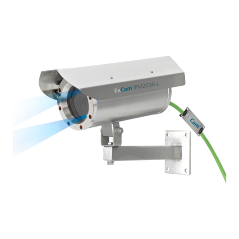
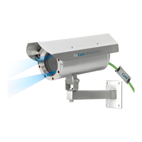
Figure 1.1 –RoughCam IPM1145-L with wall mount bracket and roof..............................5
Figure 2.1 –RoughCam IPM1145-L................................................................................10
Table 4.1 –Model key.....................................................................................................13
Figure 5.1 –RoughCam IPM1145-(L) potential equalization...........................................16
Table 5.1 –Potential equilization.....................................................................................16
Figure 5.2 –Cable glands and supply cable....................................................................17
Figure 5.3 –RoughCam IPM1145-(L) T10-VA2.1.K1.BOR-XXX-K-X..............................17
Figure 5.4 –RoughCam IPM1145-(L) T10-VA2.1.K1.BOR-XXX-P-X..............................18
Figure 5.5 –RoughCam IPM1145-(L) T10-VA2.1.K1.BOR-XXX-X-L(L) .........................18
Table 5.2 –Pin assignment SKD01-T and plug contact RJ45.........................................19
Figure 5.6 –RJ45 Contact assignment ...........................................................................20
Figure 5.7 –SKD01-T Pin assignment ............................................................................20
Table 5.3 –Pin assignment supply cable for heating type L............................................21
Table 5.4 –Pin assigment supply cable for cooling type H .............................................21
Table 5.5 –Status and control LED.................................................................................22
Figure 5.8 –Remote Zoom control of the RoughCam IPM1145-L...................................23
Figure 5.9 –Live View with IR control of the ExCam IPM1145-L ....................................23
Table 5.6 –Lens data......................................................................................................24
Figure 5.10 –Removing the protection roof (1/2)............................................................25
Figure 5.11 –Removing the protection roof (2/2)............................................................25
Figure 5.12 –Opening the RoughCam IPxxx..................................................................26
Figure 5.13 –RoughCam IPM1145-L installation components........................................27
Figure 5.14 –MicroSD card slot......................................................................................28
Figure 6.1 –Axis IP Utility................................................................................................32
Figure 10.1 –Dimensions T10 RoughCam IPM1145-(L).................................................35
Figure 10.2 –Dimensions T10 RoughCam IPM1145-(L) accessories.............................36
Figure 10.3 –cool.Jacket (example)................................................................................37

Doc.-ID: 180516-PT10BA-ES-RoughCam IPM1145-(L)_en_rev.01.docx, page 4 of 40
Revision history
Product: T10 RoughCam® IPM1145-(L)
Title: User manual of RoughCam®IPM1145-(L)
Doc.-Id.: 180516-PT10BA-ES-RoughCam IPM1145-(L)_en_rev.01.docx
Author: Eva Schneider
Date: May 16, 2018
Last revision: Dec. 20, 2018
Rev.-
Index
Date
Name
Remarks
Authorization
0
May 16, 2018
E. Schneider
Compilation of the document
Derived from the following docu-
ment150903-PT08BA-TG-ExCam
IPM1145_en_rev.01.docx
1
Dec. 20, 2018
E.Schneider
Adding the PoE+ Versions
Digital unterschrieben von Steffen
Seibert
DN: cn=Steffen Seibert, o=SAMCON,
c=DE
Datum: 2019.01.29 16:33:25 +01'00'

Doc.-ID: 180516-PT10BA-ES-RoughCam IPM1145-(L)_en_rev.01.docx, page 5 of 40
1 Introduction
The RoughCam IPM1145-(L) is a high-performance digital camera system (type T10),
manufactured by SAMCON Prozessleittechnik GmbH. The system is intended for net-
work transmission via IP/ TCP/ RTSP protocols and Web Interface access. The device is
very compact in design, covers all relevant features of a professional CCTV surveillance
camera and is available as RoughCam IPM1145 or RoughCam IPM1145-L.
Via the data cable, the camera systems are also supplied with power via Power-over-
Ethernet (PoE IEEE802.3af/at) so that ideally only one connection cable is required.
The high-performance of the RoughCam IPM1145-(L) regarding its usage for industrial
process, plant, or person surveillance is based on a high-resolution output (1080p) to
achieve a detailed and high contrast picture quality even at difficult light settings,
day/night functionality, edge storage, individually configurable H.264 and Motion JPEG
video streams, an intelligent and fast P-Iris aperture control as well as optional I/O inter-
faces. The highly efficient infrared LEDs of the RoughCam IPM1145-L are adjustable to
meet the individual application requirements to allow a surveillance of objects also in
complete darkness.
The camera system is suitable for indoor as well as outdoor applications. It is extremely
robust and therefore perfect for even the roughest industrial conditions. The stainless
steel housing allows additional alloys, a powder coating, or coats of varnishes as well as
various mechanical accessories in order to extend the resistance towards extreme envi-
ronmental conditions (salt water, acid, solar radiation, high mechanical strains etc.). Due
to the usage of high-quality PTFE sealings, not only the protection level IP68 is reached
but also the chemical resistance is maximized.
Figure 1.1 –RoughCam IPM1145-L with wall mount bracket and roof

Doc.-ID: 180516-PT10BA-ES-RoughCam IPM1145-(L)_en_rev.01.docx, page 6 of 40
2 Technical Data
2.1 Electrical parameters of the camera module
2.1.1 RoughCam IPM1145-(L) (PoE+) (Camera and Heater)
Power supply: PoE, IEEE 802.3at type 2 class 4
Reference power: 48 V DC (44...54 V DC)
Maximum power input: 24.9 W (30 W from the PSD)
2.1.2 RoughCam IPM1145
Power supply: PoE, IEEE 802.3af/ 802.3at type 1 class 2
Reference power: 48 V DC (44...54 V DC)
Maximum power input: 6.0 W
2.1.3 RoughCam IPM1145-L
Power supply: PoE, IEEE 802.3af/ 802.3at type 1 class 3
Reference power: 48 V DC (44...54 V DC)
Maximum power input: 10.5 W
2.2 Electrical parameters of the PTC heat load circuit (optional)
Reference power UN: 24 V DC
Nominal voltage PN: 20 W at type L (TAMB ≥-30°C)
40 W at type LL (TAMB ≥-60°C)
Attention!
The power consumption of the housing heating is determined by the ambient tempera-
ture or, respectively, by the PTC features
1
found in the modules’ individual operating
points. In addition, the performance of the PTC load circuit is influenced by the switching-
on characteristics of the CB06 circuit board, the load operation of the internal camera
module as well as the convection cooling on the outside (heat dissipation via housing).
Per module, the switch-on power can reach Pmax > 100W! Supply cable fine wire fuses
have to be dimensioned accordingly by the end user. A super-slow (-TT-) trigger charac-
teristic is recommended.
The typical continuous power rating at the low temperature range (TAMB -30°C) is
P(-30°C) = 12.2 W at a saturated condition
The typical continuous power rating at the artic temperature range (TAMB -60°C) is
P(-60°C) = 26.8 W at a saturated condition
The typical start-up peak at the low temperature range (1x HP05 heating element) is
Imax > 4000mA !
The typical start-up peak at the artic temperature range (2x HP05 heating element) is
1
PHP05 = KxAxT (K=5.5W/m2)

Doc.-ID: 180516-PT10BA-ES-RoughCam IPM1145-(L)_en_rev.01.docx, page 7 of 40
Imax > 8000mA !
The typical in-rush-duration for IPTC < 1000mA per module is tON ≤45s
The typical in-rush-duration for IPTC < 500mA per module is tON ≤120s
(saturated range/ steady current)
2.3 Connection cable SKD01-T
Description: Samcon System Cable Digital (type „SKD01-T“)
for low temperature ranges, data transfer and
power supply of the camera modules M1145
and M1145-L
Sheath color: Yellow-green (GN), similar RAL6018
Outer diameter: 9.1 ± 0.2mm
Wall thickness: 1.0 ± 0.1mm
Bending radius: 10 x outer diameter at installation
5 x outer diameter after installation
Tensile: Max. 140N
Temperature range: -10° C to +50° C (at point of installation)
-60° C to +80° C (fixed installed)
Conductor design: 4 x 2 x AWG22/1 blank, CAT.6a
Isolation: SFS-PE foamed
Core diameter: 1.52 ± 0.02 mm
Color code: IEC 708-1
Pair shielding: Compound aluminum foil
Shielding: Copper braid, multiple wires 0-10 vz, opt. cov-
erage approx. 85%
Outer sheath: PUR FHF
Characteristics: PUR halogen free, flame resistant (EN 60332-
1-2), UV and ozone resistant, high chemical re-
sistance, EMV shielded
(q.v. www.samcon.eu, data sheet SKD02-T)
User interface: P(Plug) version: RJ-45 Stecker (EIA/TIA-
568B), e.g. Weidmüller IE-PS-RJ45-FH-BK,
Phoenix Contact VS-08-RJ45-5-Q/IP20 etc.,
10BASE-T/100BASE-TX PoE
K(terminal block) version: about 12 cm stripped:
8 x single conductors twisted pair (solid conduc-
tor A=0.33mm2, ø=0.64 mm approx. 6 mm
stripped), 1 x shield (Cu braid tinned 1.5 mm2,
ferule color code according to DIN 46228)
10BASE-T/ 100BASE-TX PoE

Doc.-ID: 180516-PT10BA-ES-RoughCam IPM1145-(L)_en_rev.01.docx, page 8 of 40
2.4 Power Supply cable (optional)
Description: Ölflex® 440P
2
(U.I. Lapp GmbH), power supply
for the PTC heat load circuit as well as for the
electronical regulation of the CB06 for T10
RoughCam with the model key „L“ and „LL“,
Sheath color: Silver grey (GY) matt, similar RAL7001
Outer diameter: 7.5 mm
Outer sheath: Polyurethane mixture TMPU according to EN
50363-10-2 / VDE 0207-363-10-2
Bending radius: 12.5 x outer diameter (occasional movement)
4.0 x outer diameter (fixed installation)
Conductor design: 3G1.5 (0012838), 3 x 1.5 mm2(ø=1.4 mm),
Fine wired tinned copper strand according to.
IEC 60228 / VDE 0295, class 5, with protective
earth (GN/YE)
Copper index: 43.0 kg/km
Weight: 96.0 kg/km
Tensile strength: 15 N/mm2
Characteristics: Resistant to oil and drilling fluids according to
IEC 61892-4: supplement D, wear and notching
resistant, halogen free (VDE 0472-815) and
flame-retardant according to IEC 60332-1-2, re-
sistant to hydrolysis and microbes, UV re-
sistant, additional testing requirements accord-
ing to IEC 60811, EN 50396 and EN 50396
(q.v. www.samcon.eu, data sheet Ölflex 440P)
Conductor identification code: Black conductors with white numbers with
GN/YE- protective earth according to DIN EN
50334 / VDE 0293-334
Classification: ETIM 5.0 Class-ID: EC 000104, ETIM 5.0 type:
Control cable
Conductor insulation: Thermal Plastic Elastomer (TPE)
Nominal current U0/U: 300/500 V AC/DC
Test voltage: 3000 V
Temperature range: -40°C to +90°C (occasional movement)
-50°C to +90°C (fixed installation)
User interface: P(Plug) version: n/a / upon request
K(terminal block) version: 3x 1.5 mm2(3G1.5)
Cu strand with ferules (color code according to
DIN 46228). Sheath about 12 cm stripped and
furnished with bend relief / shrink tubing
2
Further cables available upon request, e.g. „Ölflex® Petro FD 865 CP“ (high resistance against oil and drilling liquids) or „XPLE
Armoured 3 x 2.5“ (extremely robust, particularly designed for offshore environments)

Doc.-ID: 180516-PT10BA-ES-RoughCam IPM1145-(L)_en_rev.01.docx, page 9 of 40
2.5 Technical specification of the camera modules
Note:
Technical details of the internal CCTV module such as light sensitivity, resolution, frame
rate sensor, shutter times, lens details, streaming functions, supported network protocols,
event trigger, storage options, and picture parameter setting via the web interface are
thoroughly provided in the data sheets of the camera manufacturer and not part of the
T10 RoughCam user manual.
2.5.1 Axis M1145
Data sheet:
http://www.axis.com/files/datasheet/ds_M1145_1480602_en_1604.pdf
User manual:
http://www.axis.com/files/manuals/um_m1145_57266_en_1512.pdf
2.5.2 Axis M1145-L
Data sheet:
http://www.axis.com/files/datasheet/ds_m1145l_1480603_en_1506.pdf
User manual:
http://www.axis.com/files/manuals/um_m1145l_57268_en_1512.pdf
2.6 IR-LED Illumination
2.6.1 Axis M1145
Specification: n/a
(the Axis M1145 camera module does not have
integrated IR LED illumination with additional
photo diode for measuring the light conditions)
2.6.2 Axis M1145-L
Specification: 2 x highly efficient LEDs
3
- with optimized infrared spectral components
(λcentroid = 850 [nm]), allows high-contrast
black and white pictures in darkness and un-
der difficult light conditions
- Adjustable intensity and illumination angle,
typical range up to 15 m
- Light sensor for automatic activation or deac-
tivation of the infrared diodes
3
Depending on the adjusted illumination angle, it is possible that at turned on IR LED illumination, the angle of view is slightly restrict-
ed or a minor shadowing is noticeable

Doc.-ID: 180516-PT10BA-ES-RoughCam IPM1145-(L)_en_rev.01.docx, page 10 of 40
- Includes a particularly developed chloroprene
rubber adapter for limiting the scattering an-
gle due to infrared light reflections within the
pressure resistant housing (q.v. optimization
of shadowing and interferences due to multi-
ple LED light reflections at the borosilicate
sight glass of the stainless steel housing)
- Radiation angle: Max 30°
Figure 2.1 –RoughCam IPM1145-L
2.7 Temperature range (MTBF)
2.7.1 RoughCam IPM1145(-L) PoE+
Permitted functional ambient temperature (MTBF)
4
: -30 °C to +40 °C (type L)
2.7.2 RoughCam IPM1145
Permitted functional ambient temperature (MTBF) 0 °C to +40 °C (type N)
0 °C to +70 °C (type H) (T5)
-30 °C to +40 °C (type L)
-60 °C to +40 °C (type LL)
-30 °C to +70 °C (type LH) (T5)
2.7.3 RoughCam IPM1145-L
Permitted functional ambient temperature (MTBF) 0 °C to +40 °C (type N)
Axis M1145-L 0 °C to +65 °C (type H) (T5)
-30 °C to +40 °C (type L)
-60 °C to +40 °C (type LL)
-30 °C to +65 °C (type LH) (T5)
4
Functional temperature range concerning the operational temperature range of the installed non-Ex components according to AXIS
manufacture declarations (MTBF –mean time between failures) under consideration of thermal power loss and the temperature coef-
ficient of the housing.

Doc.-ID: 180516-PT10BA-ES-RoughCam IPM1145-(L)_en_rev.01.docx, page 11 of 40
2.8 Other technical data
Protection level EN 60529/ IEC 529: IP68
Test conditions (>IP67): 24h/ 3m water column,
pH-neutrality, temperature of the liquid medium:
+5° C ≤ TWater ≤ +20° C.
An additional mechanical protection against wa-
ter jets is recommended
Housing material
5
according to DIN EN 10027-2: 2015-07 (making system for steel):
Housing material (standard)MNo.: 1.4404 (X2CrNiMo17-12-2),
AISI 316L / V4A
Housing material (optional) MNo.: 1.4301 (X5CrNi18-10),
AISI 304 / V2A
MNo.: 1.4305 (X8CrNiS18-9),
AISI 303
MNo.: 1.4401 (X5CrNiMo17-12-2),
AISI 316 / V4A
MNo. 1.4571 (X6CrNiMoTi17-12-2),
AISI 316Ti / V4A
Protective coating: Standard color RAL7035 (all RAL colors
and special colors possible!), DURALMIT®
2K-PUR structure, type DSPT (isocyanate
netted, polyester modified acrylate resin, fine
structure (1.6…2.0 [mm] nozzle), surface re-
sistance ≤ 9^11[Ω], layer thickness ≤ 0.2 [mm],
screw connections, flat gaskets and cable
glands are excluded from the coating
Additional metallic/non-metallic materials
of the housing protection system: Zinced spring steel MNo.: 1.0330, PTFE with
glass microbeads (GYLON® Style 3504 blue),
silicone-coating (Silcoset 105 incl. CureAgent
28), VMQ (silicone), thermos transfer foil made
of polyester (aceton resistant), cable glands
made of brass, nickle-plated (MsNi)
Sight glass material: Borosilicate glass (Ilmadur 10/ I-420)
(DIN7080:2005-05)
5
The available stainless steel materials dispose of different specific characteristics such as mechanical and chemical resistance. It is
possible to optimize the corrosion behavior in highly acidiferous environments or at offshore applications by selecting the applicable
housing material. An electro-polished or powder-coated surface in various RAL colors (standard: RAL7035) is possible.

Doc.-ID: 180516-PT10BA-ES-RoughCam IPM1145-(L)_en_rev.01.docx, page 12 of 40
Internal materials: Aluminum die cast, zinced (protection housing
of the camera module), polyamide (PA6.6/
PA2000) and polyoxymethylen (POM) isolators
and supporting adapters, T08 aluminum univer-
sal adapter (EN AW-ALSi1MgMn), PTC-
ceramics, infrared anti-reflection adapter made
of chloroprene rubber (CR4100/ Z-150), PUR
and additional thermoplastic plastics, optical
and electronical components etc.
Attention: The Axis module is equipped with an
ML614R battery which supplies the real time
clock (RTC). These lithium button celsl (3.0 V)
dispose of 1.2 dimethoxymethane; ethylengly-
coldimethylether (EGDME), CAS-No. 110-71-4
Weight (without accessories): 4700 g (with „K1“ cable gland flange)
5950 g (with „K2“ cable gland flange)
6600 g (PoE+)
Weight accessories: 900 g (wall mount bracket WMB-L)
700 g (wall mount bracket WMB-S)
800 g (Twin adapter WMB-xTA)
650 g (Hood WPR-VA2.1)
100 g (Hinge attachment SCH-VA2.x)
450 g (clamp attachment CMB-S)
1000 g (Samcon cool.Jacket)
Further accessories upon request!
Dimension Housing (BxHxT)
6
: 113.0mm x 138.5mm x 210.2mm (K1 flange)
113.0mm x 138.5mm x 226.0mm (K2 flange)
113.0mm x 138.5mm x 260.2mm (PoE+)
Dimension with accessories (BxHxT)
7
: 135.0mm x 238.0mm x 393.0mm
(with wall mount bracket and hood)
Media resistance: Checked upon request only!
Generally: Resistance to corrosion as well as
chemically high-resistance to a variety of sub-
stances used in the industrial environment and
suitable for offshore applications (q.v. the gen-
eral specifications of stainless steel MNo.:
1.4404, surface finish of the housing, Gylon flat
sealing etc.)
6
Dimension stainless steel housing T11 VA2.1.x.x with mounting, without cable gland, without external accessories, for further / more
detailed dimension please refer to chapter 10 –Technical Drawings
7
Dimension camera housing T11 VA2.1 with wall mount bracket WMB-L and hood WPR-VA2.1 (axially aligned, maximum depth)

Doc.-ID: 180516-PT10BA-ES-RoughCam IPM1145-(L)_en_rev.01.docx, page 13 of 40
- The resistance significantly depends on the
following factors: Temperature, concentration,
duration and media type (liquid, gas, steam
etc.). The resistance towards environmental in-
fluences and mechanical strain can be maxim-
ized by an optional certified protective coating!
To increase the corrosion characteristics it is
also possible to electro-polish the applicable
components -
3 Safety guidelines
Please observe the national regulations regarding security, installation, and acci-
dent prevention for the erecting of electrical plants as well as the safety guidelines
described in this user manual!
Attention!
If components have to be repaired this must be done with original
components of the Samcon Prozessleittechnik GmbH.
4 Illustration of the model key
The following model options are currently available for the T10 RoughCam IPM1145-(L):
Model options
Product name1)
Type2)
Housing
combination3)
Cable length [m]
SKD01-T
/Ölflex®440P4)
Cable
Termin.5)
Temp.
range6)
RoughCam IPM1145
RoughCam IPM1145-L
T10-
VA2.1.K1.BOR-
005-
K-
N
T10-
VA2.1.K1.BOR-
005-
P-
N
T10-
VA2.1.K2.BOR-
005-
K-
N
T10-
VA2.1.K2.BOR-
005-
P-
N
T10-
VA2.1.K1.BOR-
005-
K-
L
T10-
VA2.1.K1.BOR-
005-
P-
L
T10-
VA2.1.K2.BOR-
005-
K-
L
T10-
VA2.1.K2.BOR-
005-
P-
L
T10-
VA2.1.K1.BOR-
005-
K-
LL
T10-
VA2.1.K1.BOR-
005-
P-
LL
T10-
VA2.1.K1.BOR-
005-
K-
H
T10-
VA2.1.K1.BOR-
005-
P-
H
T10-
VA2.1.K1.BOR-
005-
K-
LH
T10-
VA2.1.K1.BOR-
005-
P-
LH
…PoE+
T10-
VA2.2.K1.BOR-
x
x
x
Table 4.1 –Model key

Doc.-ID: 180516-PT10BA-ES-RoughCam IPM1145-(L)_en_rev.01.docx, page 14 of 40
Explanation:
1) RoughCam =Functional camera description of the T10 RoughCam Series regarding the
IPM1145-(L) installed camera module and characteristics: Sensor resolution, light sensi-
tivity, camera angle of view, aperture control, power intake, zoom charac-
teristics (wide/tele range, optical/digital, motor controlled/varifocal), special
features (e.g. IR LEDs, Lightfinder or WDR technology) etc.
2) T10 = Production type concerning the certifications of the „T10
RoughCam Series“
3) VA2.1.K1.BOR = T11 housing with large diameter (ØVA=113 mm) and large sight glass
(QBOR=72 mm) effective, translucent area)
VA2.1.K1.BOR = T11 housing with minimum body length (LVA2.1.R = 188 mm)
VA2.2.K1.BOR = T11 housing with medium body length
VA2.1.K1.BOR = K1 cable gland flange (straight cable gland(s) - Standard -
VA2.1.K2.BOR = K2 cable gland flange (orthogonal cable gland)
VA2.1.K1.BOR = Borosilicate sight glass DIN7080 (standard execution, for video cameras
within visible spectral range: λ= 350…2000 [nm]. Not suitable for thermo-
graphic applications)
4) 005 = Length of the connection line in meter at delivery. The standard cable
length is 5 m (minimum/maximum cable length: 001…100 [m])
5) K= Terminal block termination (standard)
SKD01-T: CAT6a, 8x single conductor AWG22/1 „twisted pair“ solid
conductor copper blank, 0.33 mm2 / Ø=0.64 mm, approx. 6
mm striped, 1x shield CU-braid tinned 1.5 mm2 with ferules
blue
Ölflex 440P: Supply, 3G1.5mm2, Cu Sheath about 12 cm stripped and
furnished with bend relief / shrink tubing
P= Plug- termination (optional)
SKD01-T: CAT6a, RJ-45 network plug (heavy duty), AWG 26-22,
e.g.: Type Weidmüller „IE-PS-RJ45-FH-BK“ or type
Phoenix Contact „VS-08-RJ45-5-Q/IP20“, contact assign-
ment always acc. to specification EIA/TIA-568B 1
Ölflex 440P: Q.v. terminal block termination
Plug-termination n/aor upon request
(6) N= Normal ambient temperature range (MTBF): TAMB_N: 0 to +40 [°C]
L= Low ambient temperature range (MTBF): TAMB_L: -30 to +40 [°C]
LL = Lowest ambient temperature range (MTBF): TAMB_LL: -60 to +40 [°C]
H= High ambient temperature range (MTBF): TAMB_H: 0 to +70 [°C]
LH = Broad ambient temperature range (MTBF): TAMB_LH: -30 to 70 [°C]

Doc.-ID: 180516-PT10BA-ES-RoughCam IPM1145-(L)_en_rev.01.docx, page 15 of 40
5 Commissioning
Before mounting the camera must be checked for transport or storage damage.
Attention!
Please observe the national regulations regarding security, installa-
tion, and accident prevention for the erecting of electrical plants as
well as the safety guidelines described in this user manual!
5.1 Step 1: Installation
Install the RoughCam®IPM1145-(L) at the desired location. More detailed description of
mounting options and accessories you can find on http://www.samcon.eu.
5.2 Step 2: Electrical connection
Attention!
The electrical connection of the equipment must be executed by quali-
fied personnel only!
Attention!
It is mandatory that the housing of the RoughCam®Series has to be
grounded via a PE-connection!
The RoughCam®IPM1145-(L) Series is delivered with the electrical connection cable
type SKD01-T. Optionally, the camera can dispose of a power cable (standard is a type
„Ölflex® 440P“).The maximum cable length is 100 m (depending on electromagnetic tol-
erance) and can be determined individually to reflect the particular customer specifica-
tions. The minimum cable length is 1 meter.
The RoughCam®IPM1145-(L) is manufactured with a pigtail reflecting the desired cable
length. Depending on the model option, the ending of the camera’s cable connection is
either stripped to the blank Cu conductors or furnished with a plug.

Doc.-ID: 180516-PT10BA-ES-RoughCam IPM1145-(L)_en_rev.01.docx, page 16 of 40
5.2.1 Potential equalization
Figure 5.1 –RoughCam IPM1145-(L) potential equalization
The potential equalization / earthing of the camera housing is mandatory in order to avoid
electrostatic charging and hence spark generation. The screw terminal at the lower right
hand side of the housing’s rear side is intended for that purpose (q.v. figure 5.1). The pro-
file of the potential equalization has to reflect the national grounding instructions (min.
4mm2).
Connection table:
Potential
Color (IEC 60757)
Profile
Comment
PE
GN/YE
4 mm2(fix)
Screw terminal: Slotted screw M4 x 0.7 (DIN
84) with washer Ø 9 mm (DIN 125A)), 3Nm
Tightening torque has to be observed!
Table 5.1 –Potential equilization

Doc.-ID: 180516-PT10BA-ES-RoughCam IPM1145-(L)_en_rev.01.docx, page 17 of 40
5.2.2 Connection and protection
Figure 5.2 –Cable glands and supply cable
Figure 5.3 –RoughCam IPM1145-(L) T10-VA2.1.K1.BOR-XXX-K-X
Cable gland 2 (optional)
Ölflex® 440P –Power supply for CB06
circuit board, PTC heating elements
and further devices if applicable via a
relays control (build-to-order)
Cable gland 1
SKD01-T - digital video stream,
control and power supply (PoE) of
the camera module

Doc.-ID: 180516-PT10BA-ES-RoughCam IPM1145-(L)_en_rev.01.docx, page 18 of 40
Figure 5.4 –RoughCam IPM1145-(L) T10-VA2.1.K1.BOR-XXX-P-X
Figure 5.5 –RoughCam IPM1145-(L) T10-VA2.1.K1.BOR-XXX-X-L(L)
RoughCam IPM1145(-L) Use PoE PSE for 802.3at type 1 class 3 or
Use PoE PSE for 802.3at type 2 class 4 (30W)
RoughCam IPM1145(-L) PoE+ Use PoE PSE for 802.3at type 2 class 4 (30W)
Via the 8 (+1) -wire green patch cable SKD01-T, the communication and the data transfer
to connected network devices as well as the power supply (PoE) of the camera is carried
out. In order to guarantee the power supply (Power Device, PD) of the RoughCam
IPM1145-(L), a Power-over-Ethernet component (Power Sourcing Equipment, PSE) has
to be available at the connecting side (e.g. a PoE Switch, a PoE Injector, or Midspan)

Doc.-ID: 180516-PT10BA-ES-RoughCam IPM1145-(L)_en_rev.01.docx, page 19 of 40
which meets the specification IEEE 802.3af or 802.3at Type 1 Class 3 („classification
power: 26-30 mA @48 VDC, max. feed power PSE: 15.4 W, max. removal power PD:
6.49 –12.95 W“). A 100 Mbit Ethernet Connection (100BASE-TX) is used for the
RoughCam IPM1145-(L) data transfer.
In case the camera disposes of a plug, (figure 5.4), it has to be plugged into the RJ45
PoE slot of the network device. Due to the design, a faulty connection or pin assignment
is not possible. The network device can already be supplied with power, prior to connect-
ing it to the camera, hence there is no „power ON“ priority which has to be observed.
In case the RoughCam IPM1145-(L) disposes of a terminal block termination, the correct
connection of the individual pins in accordance with EIA/TIA-568B has to be observed
(q.v. table 5.2). Generally, the pins of the same color code are to be connected.
Attention: The general specification for PoE allows different operation modes for PDs
(e.g. RoughCam IP1365, RoughCam IPM1145-L, RoughCam IPQ1775 etc.):
Mode A (end span): This is usually used by switches; the supply voltage is executed as
phantom power on the data lines. Both polarities are possible.
Mode B (mid span): This is usually used by PoE injectors; the power supply and protocol
transfer is executed on separate pins (plug / pin contact 4.5 is the positive pole and 7.8 is
the negative pole). The T10 RoughCam series supports both modes and the used power
source (PSE) determines the mode.
During operation and interaction with a visualization / video management software or dur-
ing web interface access, it is allowed disconnecting the RoughCam IPM1145-(L) from
and later reconnecting it to the network (hot plugging). The same is valid for a switching
of due to rebooting purposes.
The standard pin assignment of the SKD02-T in accordance with EIA/TIA-568B for
100BaseTX with PoE (IEEE 802.3af/at) is as follows:
Pin / Potential
Color
SKDxx
(IEC60757)
Plug /
pin contact
(TIA-568B)
Cross sec-
tion area
Remarks
Mode A
Mode B
Tx+ / PoE ±48 VDC
Tx+
WH / OG
1
0.64 mm2
Solid conductor
Tx- / PoE ±48 VDC
Tx-
OG
2
0.64 mm2
Solid conductor
Rx+ / PoE GND
Rx+
WH / GN
3
0.64 mm2
Solid conductor
n.a.
PoE +48 VDC
BU
4
0.64 mm2
Solid conductor
n.a.
PoE +48 VDC
WH / BU
5
0.64 mm2
Solid conductor
Rx- / PoE GND
Rx-
GN
6
0.64 mm2
Solid conductor
n.a.
PoE GND
WH / BN
7
0.64 mm2
Solid conductor
n.a.
PoE GND
BN
8
0.64 mm2
Solid conductor
shield/ GND
(complete conductor bunch)
BK
9
n/a
Shield braid of
tinned copper wires
Ø=0.13 mm
(AWG 36)
shield
(single, twisted pair pins)
n/a
n/a (10)
n/a
Aluminum synthetic
strapp, twisted
Table 5.2 –Pin assignment SKD01-T and plug contact RJ45

Doc.-ID: 180516-PT10BA-ES-RoughCam IPM1145-(L)_en_rev.01.docx, page 20 of 40
Figure 5.6 –RJ45 Contact assignment
Particularly in EMC critical environments, it is important to earth the shield at the terminal
block side (q.v. figure 5.3 –pin with black shrink tubing and blue ferule).
Figure 5.7 –SKD01-T Pin assignment
In case the RoughCam IPM1145-(L) is supplied via a PoE capable device, an additional
safeguarding of the power supply is not necessary. The power supply is executed by the
PoE network device via an electronic with intelligent set-up. The camera as well as the
connection is permanently monitored in order to avoid any failure or defects in case of a
short-circuit fault. For a camera with terminal block execution, it is possible to operate the
camera either with a PoE capable network device or with a separate 48 V DC power
supply (BTO, supply voltage and network streams are self-sustaining). In this event an
adequate supply safeguarding has to be dimensioned.
Recommended is a 300 mA medium time lag fuse.
If the CCTV application calls for a separate 48 V DC supply voltage, the wire/pin assign-
ment has to reflect Mode B operation mode (q.v. table 5.2)!
4
2
6
3
9 (shield/
GND)
5
8
7
1
10 (shield)
9
This manual suits for next models
1
Table of contents
Other Samcon Security Camera manuals

Samcon
Samcon ExCam Series T08 User manual

Samcon
Samcon ExCam IPQ6055 User manual

Samcon
Samcon ExCam IPM1145 User manual

Samcon
Samcon ExCam XF Q1645 User manual

Samcon
Samcon RoughCam IPP1275 User manual

Samcon
Samcon RoughCam IPM3016 User manual

Samcon
Samcon ExCam niteZoom User manual

Samcon
Samcon ExCam XPT Q6075 User manual

Samcon
Samcon ExCam miniZoom User manual

Samcon
Samcon RoughCam IPM2036 User manual