Samcon RoughCam IPM3016 User manual

RoughCam IPM3016
User Manual

Doc.-ID: 181210-PT10BA-ES-RoughCam IPM3016_en_rev.00.docx, page 2 of 24
Content
1Introduction ..............................................................................................................4
2Technical Data..........................................................................................................4
2.1 Illustration of the model key.................................................................................4
2.2 Electrical parameters...........................................................................................5
2.3 System cable.......................................................................................................6
2.4 Technical specification of the camera module.....................................................6
2.5 Other technical data............................................................................................7
3Safety guidelines......................................................................................................8
4Commissioning ........................................................................................................9
4.1 Step 1: Installation...............................................................................................9
4.2 Step 2: Electrical connection...............................................................................9
4.2.1 Potential equalization...............................................................................................................10
4.2.2 Connection and protection.......................................................................................................11
4.2.3 Connector pin assignment (RJ45)...........................................................................................12
4.2.4 Connection work on the terminal box ......................................................................................13
4.2.5 Tests prior to switching on voltage ..........................................................................................16
5Hardware Reset......................................................................................................17
5.1 Work preparation...............................................................................................17
5.2 Opening the housing.........................................................................................17
5.3 Closing of the housing.......................................................................................19
6Network access and visualization ........................................................................20
6.1 Browser Support................................................................................................20
6.2 Assigning the IP address...................................................................................20
6.3 Password / identification....................................................................................21
7Maintenance / Servicing / Alterations...................................................................21
8Repairs and Maintenance......................................................................................21
9Disposal / Recycling ..............................................................................................21
10 Drawings..............................................................................................................22

Doc.-ID: 181210-PT10BA-ES-RoughCam IPM3016_en_rev.00.docx, page 3 of 24
Table of Figures
Table 2.1 –Model key.......................................................................................................4
Figure 4.1 –PE connection RoughCam IPM3016...........................................................10
Table 4.1 –Potential equalization....................................................................................10
Figure 4.2 –Cable gland with cable ................................................................................11
Figure 4.3 –RoughCam IPM3016 T10-VA1.2.K1.BOR-N.N-xxx.N-T-0xx.......................11
Figure 4.4 –RoughCam IPM3016 T10-VA1.2.K1.BOR-N.N-xxx.N-P-0xx.......................11
Figure 4.5 –RoughCam IPM3016 T10-VA1.2.K1.BOR-LL.N-xxx.N-P-0xx .....................12
Figure 4.6 –RJ45 Pin assignment and cable pin assignment.........................................12
Table 4.2 –Electrical connection for model key „N.N“.....................................................14
Table 4.3 –Electrical connection for model key “LL.N“ ...................................................15
Figure 4.8 –Connection to the terminal box (models with heating).................................16
Figure 5.1 –Opening the RoughCam IPM3016...............................................................17
Figure 5.2 –Location of the control button ......................................................................18
Figure 5.3 –Disconnecting the mounting adapter ...........................................................18
Figure 10.1 –Dimensions of the T10 RoughCam IPM3016 ............................................23
Revision history
Product: T10 RoughCam IPM3016
Title: User manual RoughCam IPM3016 Type 10
Doc. -Id. 181210-PT10BA-ES-RoughCam IPM3016_en_rev.00.docx
Author: Eva Schneider
Date: December 10, 2018
Latest update: December 10, 2018
Rev.- Index
Date
Name
Remarks
Authorization of the EX Supervisor
0
Dec 10, 2018
E.Schneider
Compilation of the document
Digital unterschrieben von
Steffen Seibert
DN: cn=Steffen Seibert,
o=SAMCON, ou,
, c=DE
Datum: 2018.12.12 09:45:51
+01'00'

Doc.-ID: 181210-PT10BA-ES-RoughCam IPM3016_en_rev.00.docx, page 4 of 24
1 Introduction
The RoughCam IPM3016 is a very compact and robust digital camera (type T10) which is
manufactured by SAMCON Prozessleittechnik GmbH and can be used very flexibly for
various applications. Due to its dimensions and adaption options as well as the exchange-
able lenses with various angle of views, focal length and areas of focus, even sight glass
applications and process observations with only little object distances are possible.
Besides for fixed installation, the RoughCam IPM3016 is also certified to be used for mo-
bile applications (hand-held).
Due to the usage of high-quality PTFE sealings, not only the protection level IP68 is met
but also the chemical resistance is maximized.
2 Technical Data
2.1 Illustration of the model key
Modelvariants
Options
Productname1)
Type
2)
Housing
combination3)
Temperature
range4)
Cable length/m
5)
Cable
termin.6)
Lens7)
RoughCam
IPM3016
T10-
VA1.2.K1.BOR-
N.N-
005.N-
P-
090/046/017
T10-
VA1.2.K1.BOR-
N.N-
005.N-
T-
090/046/017
T10-
VA1.2.K1.BOR-
LL.N-
005.N-
T-
090/046/017
Table 2.1 –Model key
Explanations:
1) RoughCam IPM3016 = Functional camera description of the RoughCam (technical data /
specification of the individual camera module)
2) T10 = SAMCON Production type 10 (for safe areas)
3) VA1.2.K1.BOR = T11 housing (stainless steel 1.4404) with small diameter (ØVA=79mm)
VA1.2.K1.BOR = T11 VA1.x housing with maximum body length (LVA1.2.R = 136mm)
VA1.2.K1.BOR = K1 cable gland flange (axial cable gland, standard)
VA1.2.K1.BOR = Borosilicate sight glass DIN7080 standard execution, for video cameras
within visible spectral range and photographical infrared range (NIR), not
suitable for thermographic applications (MIR/ FIR)
4) N.N= Normal ambient temperature range, no heater installed (Tamb > -5°C)
N.N= No cooling system installed (Tamb < +55°C)
LL.N= PTC heater installed (Tamb > -60°C)
5) 005.N = Length of the connection line in meter at delivery. The standard cable
length is 5 m, minimum/ maximum cable length is: 001…095 [m] for

Doc.-ID: 181210-PT10BA-ES-RoughCam IPM3016_en_rev.00.docx, page 5 of 24
model key -N- and 001…005 [m] for model key -LL-
005.N= Non armoured cable
6) P= Plug- termination (standard)
CAT6, RJ-45 network plug (heavy duty), AWG 26-22,
contact assignment acc. to specification EIA/TIA-568B
Attention:
Only possible for model key N (without heating).
T = Terminal box termination (optional)
4 x PoE Mode A Anbindung (Camera PoE)
24VDC (Heater) (see chapter 4.2 electrical connection)
7) Lens Options
Models
Lens
Iris
Horizontal
AoV@16/9
Horizontal
AoV@4/3
T10-VA.1.2.K1.BOR-X.X-XXX.X-X-090 (wide (standard))
Megapixel lens 2,8mm
F2.6
90°
78°
T10-VA.1.2.K1.BOR-X.X-XXX.X-X-046 (normal)
Megapixel lens 6mm
F2.0
46°
34°
T10-VA.1.2.K1.BOR-X.X-XXX.X-X-017 (tele)
Megapixel lens 16mm
F1.8
17°
12°
2.2 Electrical parameters
Power supply camera: PoE, IEEE 802.3af/ 802.3at
Type 1 class 1, typical 2.9 W, max. 3.8 W
(LL models only MODE A PSE-devices!)
Power supply heater: 20W@-60°C@24VDC
Attention!
Per module, the switch-on power can reach Pmax > 100W! Supply cable fine wire fuses
have to be dimensioned accordingly by the end user.
It is recommended to use for example Typ: 2000 mA -T- time-lag (ESKA UL-microfuse
20x5mm)
The typical continuous power rating at the artic temperature range (TAMB -60°C) is
P(-60°C) = 14.8 W at a saturated condition
The typical start-up peak at the artic temperature range (-60°C) is Imax ≈4860mA!
The typical in-rush-duration for IPTC < 1000mA per module is tON ≤45s
The typical in-rush-duration for IPTC < 500mA per module is tON ≤120s (saturated range/
steady current)

Doc.-ID: 181210-PT10BA-ES-RoughCam IPM3016_en_rev.00.docx, page 6 of 24
2.3 System cable
Outer diameter: 8.7 ± 0.3mm
Bending radius: 8 x outer diameter at installation
4 x outer diameter after installation
Temperature range: -25°C to +80°C (at point of installation)
-60°C to +80°C (fixed installed)
Conductor design: 4 x 2 x AWG24/7 blank, CAT.6
Shielding: Copper braid, multiple wires 0-10 vz, opt. cover-
age approx. 80%
Outer sheath/characteristics: PUR FHF, halogen free, flame resistant (EN
60332-1-2), EMV shielded
2.4 Technical specification of the camera module
Please note:
Technical details of the internal CCTV module such as light sensitivity, resolution, frame
rate sensor, shutter times, lens details, streaming functions, supported network protocols,
event trigger, storage options, and picture parameter setting via the web interface are
thoroughly provided in the data sheets of the camera manufacturer and not part of the
T10 RoughCam user manual.
The Axis M3016
Data sheet:
https://www.axis.com/en-ca/products/axis-m3016/support-and-documentation
https://www.axis.com/files/datasheet/ds_m3016_t10104240_de_1809.pdf
User manual:
https://www.axis.com/files/manuals/um_m30_1741648_en_1709.pdf
Assigning IP addresses and accessing video streams:
https://www.axis.com/files/manuals/um_howtoassignanipad-
dress_t10118032_de_1801.pdf.pdf
Installation guide:
https://www.axis.com/files/manuals/ig_m30_1788577_en_1710.pdf

Doc.-ID: 181210-PT10BA-ES-RoughCam IPM3016_en_rev.00.docx, page 7 of 24
2.5 Other technical data
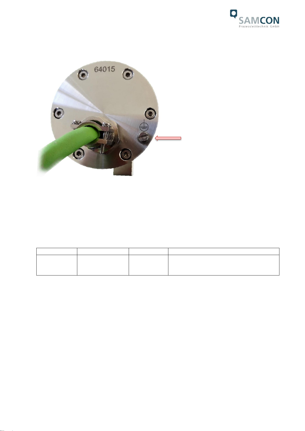
Protection level: IP 68 (IEC/ EN 60529)
Transportation / storage temperature: 5°C … +55°C
Ambient temperature: -60°C … +55°C (Type:…LL.N…)
-5°C … +55°C (Type:…N.N…)
Housing material of the enclosure according to DIN EN 10027-2: 2015-07 (designation
system for steel):
Housing material (standard)MNo.: 1.4404 (X2CrNiMo17-12-2),
AISI 316L / V4A
Additional metallic and non-metallic materials of the T11 VA1.2.x.x
housing: Zinced spring steel MNo.: 1.0330, PTFE with
glass microbeads (GYLON Style 3504 blue),
silicone-coating (Silcoset 105 incl. CureAgent
28), VMQ (silicone), thermos transfer foil made
of polyester (acetone resistant), cable glands
made of brass, nickel-plated (MsNi)
Sight glass material: Borosilicate glass “Ilmadur 10/ I-420”
Internal materials: Optical and electronical components, div. ther-
moplastic plastics: polyamide (PA6.6/ PA2000)
and polyoxymethylene (POM) isolators and
supporting adapters, Aluminum die cast, zinced
(aluminum universal adapter (EN AW-
ALSi1MgMn), PTC-ceramics, PUR, etc.
Weight (without accessories): 3,000 g
Weight of accessories: 800 g (wall mount bracket WMB-S)
400 g (hood WPR-VA1.2)
50 g (hinge attachment SCH-VA1.x)
(further accessories upon request)
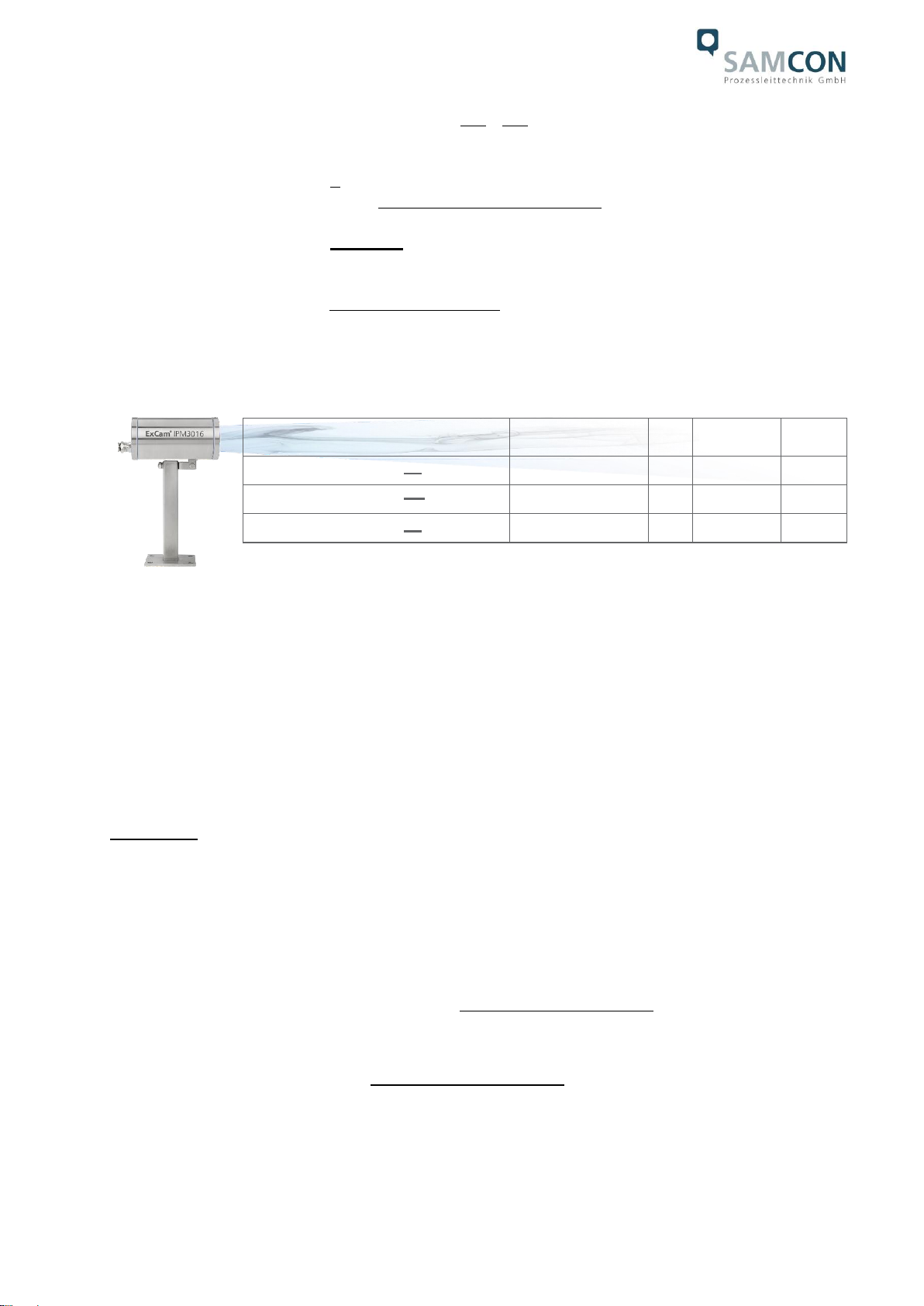
Dimensions housing (wxhxd): 79.0mm x 96.0mm x 158.0mm
Dimensions with accessories (WxHxD): 97.0mm x 193.0mm x 299.5mm
(with wall mount bracket and hood)
Media resistance: Exclusively checked upon request!
Generally: corrosion resistant, as well as chemi-
cal highly resistant against a variety of fluid and
gaseous components of the industriel area and

Doc.-ID: 181210-PT10BA-ES-RoughCam IPM3016_en_rev.00.docx, page 8 of 24
suitable for offshore applications (see general
specification of stainless steell MNo.:1.4404 /
AISI316L), surface finish and modification of the
Ex d housing
1
, elastomer sealings of the ca-
bles, as well as the GYLON flat seals of the
housing flange, etc.)
3 Safety guidelines
Please observe the national regulations regarding security and accident prevention
and the safety guidelines given below in this user manual!
Attention!
Only original parts of SAMCON Prozessleittechnik GmbH may be used
for repairs. Repairs only be carried out in accordance with the nationally
applied regulations and by SAMCON Prozessleittechnik GmbH.
Attention!
External heat and/ or cooling sources are to be taken into account dur-
ing the setting up. The permissible temperature range for transporta-
tion, storage, and operation of the camera has to be observed
Prior to the first use, you should test the camera corresponding to the instructions
given in the chapter Commissioning.
1
Protective coating, electro polishing, etc. …

Doc.-ID: 181210-PT10BA-ES-RoughCam IPM3016_en_rev.00.docx, page 9 of 24
4 Commissioning
For the camera’s installation and operation, the relevant national regulations, as well as
the generally accepted rules of technology shall prevail. Before mounting the camera, thor-
oughly check it for any transport damage, especially at the housing and cable. Installation,
electrical connection and the first commissioning must only be carried out by qualified per-
sonnel.
Attention!
Please observe the national regulations regarding security, installation,
and accident prevention as well as the safety guidelines described in
this user manual!
4.1 Step 1: Installation
Install the RoughCam IPM3016 at the desired location. You can found mounting options
and additional accessories at http://samcon.eu.
Attention!
Prior to the camera installation, take external sources of heat or cold
into account! Observe the permissible temperature range!
4.2 Step 2: Electrical connection
Attention!
The electrical connection of the equipment must be executed by quali-
fied personnel only!
Attention!
It is mandatory that the housing of the RoughCam Series has to be
grounded via a PE-connection!
The T10 RoughCam IPM3016 is delivered with the electrical connection. The maximum
cable length (PD to PSE) is 95 m (depending on electromagnetic tolerance/ EMC environ-
ment) and can be determined individually to reflect the particular customer specifications.
The RoughCam IPM3016 is manufactured with a cable pigtail reflecting the desired cable
length. Depending on the model option, the ending of the camera’s cable connection is
either furnished with a plug or connected to the terminal box.

Doc.-ID: 181210-PT10BA-ES-RoughCam IPM3016_en_rev.00.docx, page 10 of 24
4.2.1 Potential equalization
Figure 4.1 –PE connection RoughCam IPM3016
The potential equalization (graunding of the camera housing) is mandatory in order to
avoid electrostatic charging and hence spark generation. The screw terminal on the
housing’s rear side is intended for this purpose (q.v. figure 4.1). The profile of the
potential equalization has to reflect the national grounding instructions (min. 4 mm2).
Connection table:
Potential
Color (IEC 60757)
Profile
Comment
PE
GN/YE
4 mm2(fix)
Screw terminal: Slotted screw M4 x 0.7 (DIN
84) with washer Ø 9 mm (DIN 125A). 3Nm
tightening torque has to be observed!
Table 4.1 –Potential equalization

Doc.-ID: 181210-PT10BA-ES-RoughCam IPM3016_en_rev.00.docx, page 11 of 24
4.2.2 Connection and protection
Figure 4.2 –Cable gland with cable
Figures 4.3 –4.5 illustrate the possible cable terminations available for the RoughCam
IPM3016. Possible cable terminations are terminal block, plug, or the hybride execution
for the optional heating (attention: IEEE PoE specification then does not apply anymore!)
Figure 4.3 –RoughCam IPM3016 T10-VA1.2.K1.BOR-N.N-xxx.N-T-0xx
Figure 4.4 –RoughCam IPM3016 T10-VA1.2.K1.BOR-N.N-xxx.N-P-0xx
Cable
Cable gland:
ADE 4F MsNi Type5 - M20x1.5 with
additional strain relief

Doc.-ID: 181210-PT10BA-ES-RoughCam IPM3016_en_rev.00.docx, page 12 of 24
Figure 4.5 –RoughCam IPM3016 T10-VA1.2.K1.BOR-LL.N-xxx.N-P-0xx
Via the 8 (+1) wire green patch cable the digital video stream is transferred via IP/ TCP/
RTSP protocol levels and the camera module is controlled and/or parametrized via the
web interface or the video management software.
The power supply of the PoE camera and the optional heating mode (none-PoE) is con-
ducted via this cable. In order to guarantee the power supply of the T10 RoughCam
IPM3016 (Powered Device/ PD), a Power-over-Ethernet component (Power Sourcing
Equipment, PSE) has to be available at the connecting side (e.g. a PoE Switch, a PoE
Injector, or Midspan) which meets the specification IEEE 802.3af or 802.3at type 1 class
1
2
. The interface of the RoughCam IPM3016 uses a 100 Mbit/s „Fast Ethernet“- connec-
tion for the data transfer (100BASE-TX).
4.2.3 Connector pin assignment (RJ45)
In case the camera disposes of a plug (figure 4.4); it has to be plugged into the RJ45
PoE slot of the network device. Due to the design, a faulty connection or pin assignment
is not possible. The network device can already be supplied with power, prior to connect-
ing it to the camera, hence there is no „power ON“ priority which has to be observed.
Figure 4.6 –RJ45 Pin assignment and cable pin assignment
2
Classification power: 9-12 mA, nominal voltage 48 V DC (44…54 V DC),maximum feed power PSE: 4.0 W, removal performance PD: 0.44 W – 3.84 W
9

Doc.-ID: 181210-PT10BA-ES-RoughCam IPM3016_en_rev.00.docx, page 13 of 24
4.2.4 Connection work on the terminal box
If the RoughCam IPM3016 disposes of a terminal block termination, the correct connec-
tion of the individual pins in accordance with EIA/TIA-568B has to be observed (q.v. table
4.2). Generally, the pins of the same color code (IEC60757) are connected. If the Rough-
Cam IPM3016 is equipped with a PTC housing heating, particular connection conditions
apply (camera (PoE) and heating load circuit (24 VDC) have to be supplied separately
(q.v. table 4.3)).
Attention: The general specification for PoE allows different operation modes for PDs:
Mode A (end span): This is usually used by switches; the supply voltage is executed as
phantom power on the data lines. Both polarities are possible.
Mode B (mid span): This is usually used by PoE injectors; the power supply and protocol
transfer is executed on separate pins (plug / pin contact 4.5 is the positive pole and 7.8 is
the negative pole). The T10 RoughCam Series supports both modes and the used power
source (PSE) determines the mode.
Important: If the RoughCam IPM3016 is delivered with a heating (model key LL, figure
4.5), only four wires are available for PoE. In this case, the PSE has to be operated in
mode A (phantom power - q.v. wire assignment table 4.3). The applicable devices on the
connection side should be checked upfront regarding suitability. If you need support,
please get in touch with support@samcon.eu.
It is also allowed to separate and re-connect the RoughCam IPM3016 from the network
when in operation and/or when interacting with the visualization software (hot plugging),
or, if necessary, to reboot it for carrying out a re-parametrization or set it back to default.
Attention: „Hot plugging“ as well as the connection and separation of the data and
power cable from/of network devices and terminal blocks under power is allowed
within the safe area.

Doc.-ID: 181210-PT10BA-ES-RoughCam IPM3016_en_rev.00.docx, page 14 of 24
For model key „N“ (RoughCam without PTC heating) the pin assignment is in accord-
ance with the standard EIA/TIA-568B for 100BaseTX with PoE (IEEE 802.3af/at):
Camera side / Internal Wiring
System Cable
Junction
Box
Pin/ Potential
100BaseTx/PoE
Color
(IEC60757)
Plug
contact
(TIA-
568B)
Profile
AWG24/7
Terminal
Comments
Area
[mm2]
Diameter
[mm]
Mode A
Mode B
-
-.
PE
(enclosure)
SHD.
-
-
PE
SHD
Tx+ /
PoE ±48 VDC
Tx+
WH / OG
1
0.23
0.61
1
Tx- /
PoE ±48 VDC
Tx-
OG
2
023
0.61
2
Rx+ /
PoE GND
Rx+
WH / GN
3
0.23
0.61
3
Rx- /
PoE GND
Rx-
GN
6
0.23
0.61
4
n.a.
PoE
+48 VDC
WH / BU
5
0.23
0.61
5
n.a.
PoE
+48 VDC
BU
4
0.23
0.61
6
n.a.
PoE
GND
WH / BN
7
0.23
0.61
7
n.a.
PoE
GND
BN
8
0.23
0.61
8
Shield A/ GND
(twisted pair)
-
GND
(Plug)
-.
-
PE.
PE
n.c.
n.c.
n.c.
n.c.
n.c.
n.c.
9
n.c.
n.c.
n.c.
n.c.
n.c.
n.c.
10
-.
-
-
PE
Table 4.2 –Electrical connection for model key „N.N“
Particularly in EMC critical environments, it is necessary to make sure that the cable shield is
grounded on side of the terminal block (wire and pin contact No. 9, q.v. figure 4.6). The
maximum cable length between camera and junction box for models without heating is
95 m.

Doc.-ID: 181210-PT10BA-ES-RoughCam IPM3016_en_rev.00.docx, page 15 of 24
For model key „LL“ (RoughCam with PTC heating) the wires of the system cables are,
for marshalling the PoE transmission and heating supply, assigned as follows:
Camera side / Internal Wiring
System Cable
Junction
Box
Pin/ Potential
100BaseTx/PoE
Color
(IEC60757)
Plug
contact
(TIA-
568B)
Profile
AWG24/7
Terminal
Comments
Area
[mm2]
Diameter
[mm]
Mode A
Mode B
-
-.
PE
(enclosure)
SHD.
-
-
PE
SHD
Tx+ /
PoE ±48 VDC
Tx+
WH / OG
1
0.23
0.61
1
Tx- /
PoE ±48 VDC
Tx-
OG
2
023
0.61
2
Rx+ /
PoE GND
Rx+
WH / GN
3
0.23
0.61
3
Rx- /
PoE GND
Rx-
GN
6
0.23
0.61
4
n.c.
n.c.
n.c.
n.c.
5
n.c.
n.c.
n.c.
n.c.
6
n.c.
n.c.
n.c.
n.c.
7
n.c.
n.c.
n.c.
n.c.
8
Shield A/ GND
(twisted pair)
-
GND
(Plug)
FOIL.
-
PE.
PE
L+ /
+24 VDC
n.a.
WH / BN
BN
-
2 x
0.23
2 x
0.61
9
L+ (Heater)
L- /
GND
n.a.
WH / BU
BU
-
2 x
0.23
2x
0.61
10
L- (Heater)
PE
Table 4.3 –Electrical connection for model key “LL.N“
The maximum cable length for models with heater is 5m from the camera to the Ex-e ter-
minal box.
Attention!
Perform the foiling up to about 10mm to the terminals, in order to pre-
vent alien over speak. Make sure that the foiling cannot cause any short
circuit of the data couples!
Attention!
Bring the twisted pair composite approximately 10mm close to the ter-
minals, in order to ensure the immunity to disturbance.
Attention!
Use only terminals approved by SAMCON.

Doc.-ID: 181210-PT10BA-ES-RoughCam IPM3016_en_rev.00.docx, page 16 of 24
Attention!
Finally, check your network installation by per Class-D Link Test.
Figure 4.8 –Connection to the terminal box (models with heating)
4.2.5 Tests prior to switching on voltage
Attention!
Prior to commissioning, all tests as indicated by the national regula-
tions have to be executed. In addition, it is mandatory that the proper
functioning of the operating device in accordance with this user manual
and all other applicable regulation has been executed.
Attention!
Incorrect installation and operation of the camera may lead to a loss of
warranty!
Attention!
Do not switch on the camera at temperatures below -5°C!
PoE 802.3af
100 BASE TX
Ethernet
Power
heating

Doc.-ID: 181210-PT10BA-ES-RoughCam IPM3016_en_rev.00.docx, page 17 of 24
5 Hardware Reset
A hardware reset should only be carried out under the following conditions: The camera
is not accessible in the network even though it has been disconnected from power, after
a failed firmware update, or a factory reset has been explicitly asked for. For carrying out
a hardware reset it is allowed to open the housing. All required steps are described in
chapters 5.1 to 5.3 of this user manual.
5.1 Work preparation
Attention!
Please carry out any preoperational work carefully and in accordance
with the applicable regulations.
Use appropriate tools
Make sure you have a secure foothold
Avoid static charge
5.2 Opening the housing
Opening the camera housing is only allowed to carry out the hardware reset of the M3016
camera module. The steps below have to be followed very carefully:
Figure 5.1 –Opening the RoughCam IPM3016

Doc.-ID: 181210-PT10BA-ES-RoughCam IPM3016_en_rev.00.docx, page 18 of 24
Attention!
Beware not to damage the surface of bore hole and shaft (fit).
Attention!
Please make sure not to damage housing sealings and to keep them
clean.
The two control buttons are located on the Axis modules main board (q.v. Figure 5.2); the
outer push button is used for carrying out the hardware reset.
Figure 5.2 –Location of the control button
In order to be able to press the control button, the black mounting adapter has to be dis-
connected from the stainless steel flange. To do so, please take off the M3*0.5 16 mm
cylinder head screws (DIN 912) with the associated washers (DIN 127 A) (q.v. figure 5.3)
Figure 5.3 –Disconnecting the mounting adapter

Doc.-ID: 181210-PT10BA-ES-RoughCam IPM3016_en_rev.00.docx, page 19 of 24
Attention: Via a „heavy duty“ RJ45 network plug, the hardware is connected to the system
cable. For low temperature models, there are also two further wires (BK) and an additional
plug connection (WH) to the heating module. It is not mandatory to unplug the RJ45 plug
but it might facilitate the handling. If the cable is unplugged, please make sure to re-loop it
later on.
Carefully tilt the mounting adapter so that through the opening, the right push button can
be pressed to carry out the hardware reset (q.v. Figure 5.2).
Please make sure not to damage any electrical installations, cable interfaces, the lens, or
the mounting components. Also, please do not to exert mechanical strain on the aforemen-
tioned components. Please be aware that the measures run a risk of distorting the optical
axis which leads to a reduction in the picture quality!
When touching electrical components, potential equalization (ground-
ing of the body) has to be observed (ESD clothing, PE wristband etc.)!
For carrying out the hardware reset, please refer to the Axis user manual (page 15) which
describes the individual steps:
https://www.axis.com/files/manuals/um_m30_1741648_en_1709.pdf
After the successful hardware reset, the mounting adapter has to be fixed again with the
three M3*0.5 original screws and the associated washers. A tightening torque of 2.5 Nm
is recommended!
When closing the housing, the cable routing has to be observed! In order to avoid colli-
sions and mechanical strain within the closed housing as well as to observe the neces-
sary bending radius, the cable has to be looped.
5.3 Closing of the housing
ATTENTION!
Do not lock-in any foreign objects in the housing
Cylinder head scrrews always have to be tightened evenly and
crosswise with a tightening torque of 3.0 Nm

Doc.-ID: 181210-PT10BA-ES-RoughCam IPM3016_en_rev.00.docx, page 20 of 24
6 Network access and visualization
For a comprehensive user manual of the web surface, please refer to the to the Axis user
manual: https://www.axis.com/files/manuals/um_m30_1741648_en_1709.pdf
At delivery, the RoughCam IPM3016 is set to the applicable net frequency (50Hz or
60Hz). If the camera is used at a location with a differing net frequency, a flickering of the
picture might be noticeable, particularly in surroundings with fluorescent tubes. In such a
case, the applicable settings have to be carried out within the menu “System Options >
Advanced > Plain Config”, requiring a system restart.
6.1 Browser Support
A list with the currently supported web browsers, operating systems, and required add-
ons can be viewed at:
http://www.axis.com/techsup/cam_servers/tech_notes/browsers.htm
6.2 Assigning the IP address
The RoughCam IPM3016 is an Ethernet network camera requiring an IP address to ac-
cess it. Usually a DHCP server is integrated in most networks which automatically as-
signs an IP address. In case there is no DHCP server available in the network, the
RoughCam IPM3016’s default address “192.168.0.90” (subnet masking 255.255.255.0)
is used.
With the “AXIS IP Utility“ tool it is possible to determine the IP address with Windows; the
software as well as additional useful tools can be downloaded free from the homepage.
http://www.samcon.eu/en/info-center/drivers-software/
In case it is not possible to assign the IP address, it might be necessary
to change the firewall settings or to consult the network administrator!
The “AXIS IP Utility“ tool automatically recognizes all RoughCam devices and displays
them (also subnet overlapping). With this application also the static IP address can be set
manually. In this case, the RoughCam IPM3016 network camera should be installed in
the same network segment (physical subnet) as the PC on which the AXIS IP Utility is
executed.
Table of contents
Other Samcon Security Camera manuals

Samcon
Samcon ExCam niteZoom User manual

Samcon
Samcon ExCam XPT Q6075 User manual

Samcon
Samcon ExCam IP1354 User manual

Samcon
Samcon RoughCam IPP1275 User manual

Samcon
Samcon ExCam Series T08 User manual

Samcon
Samcon RoughCam IPM2036 User manual

Samcon
Samcon ExCam IPM1145 User manual

Samcon
Samcon ExCam miniZoom User manual

Samcon
Samcon ExCam IPQ6055 User manual

Samcon
Samcon ExCam IPM2036 User manual