Samcon ExCam IPM2036 User manual

ExCam®IPM2036
User Manual

Doc.-ID: 220607-PT08BA-ES-ExCam IPM2036_en_rev.00.docx, Page 2 of 36
Table of contents
1Introduction ..............................................................................................................4
2Technical data ..........................................................................................................4
2.1 Explosion protection............................................................................................4
2.2 Illustration of the model key.................................................................................5
2.3 Electrical parameters of the camera....................................................................6
2.4 Connection cable Ex-d - Ex-e..............................................................................7
2.4.1 Connection cable for models without cooling (SKD02-T/ASKD02-T)........................................7
2.4.2 Connection cable for model with cool.Jacket (SKD05-HT) .......................................................8
2.5 Video-technical characteristics............................................................................8
2.6 Other technical data............................................................................................8
2.7 IR-LED illumination..............................................................................................9
2.7.1 Settings for automatic switching to night mode .........................................................................9
2.7.2 Optimize IR illumination.............................................................................................................9
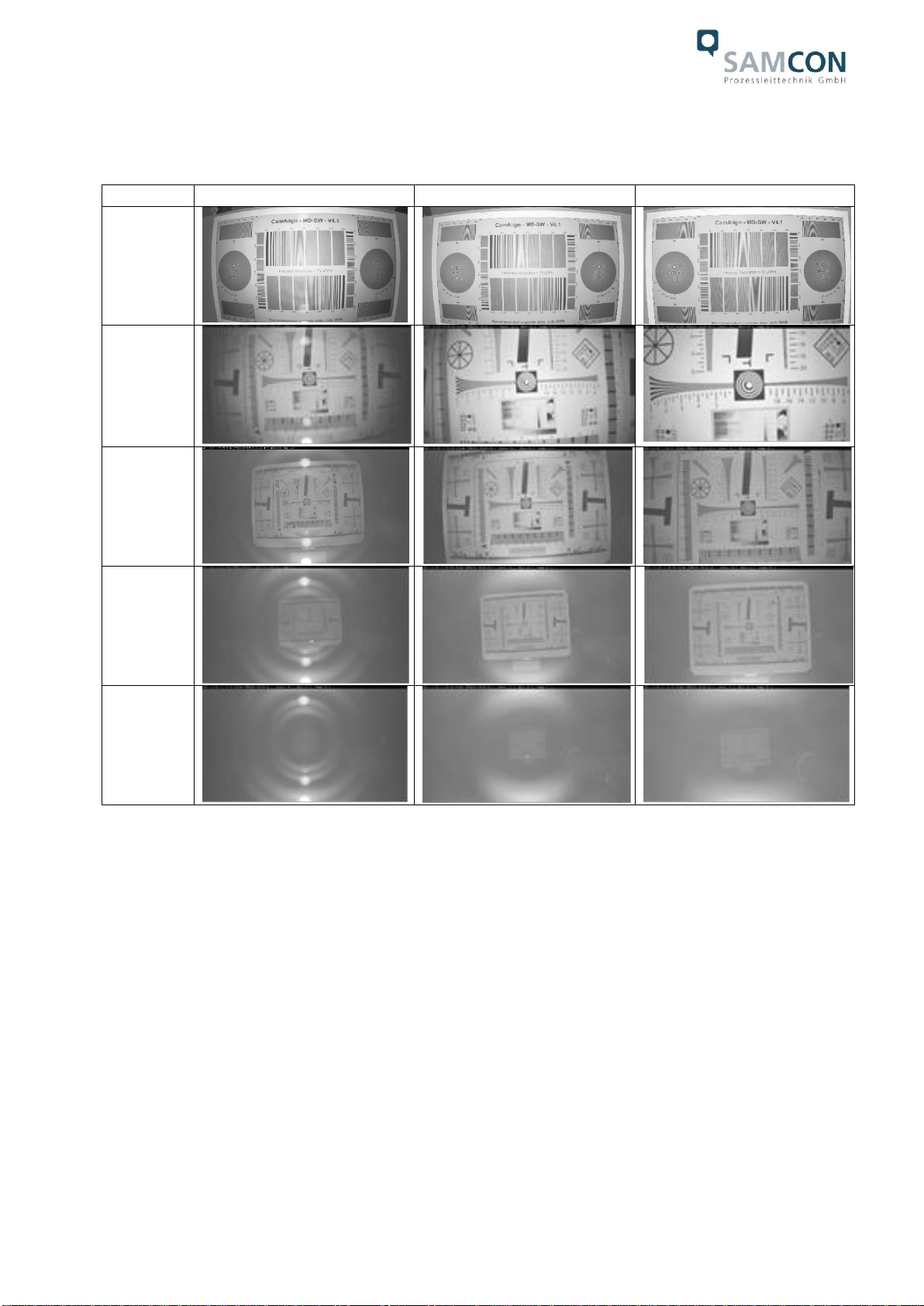
2.7.3 Illumination tests......................................................................................................................10
3Safety Instructions.................................................................................................11
4Installation ..............................................................................................................12
5Electrical connection .............................................................................................14
5.1 Potential equalization........................................................................................14
5.2 Connection work at the device (terminal box) and fuses...................................15
5.3 External connection and protection...................................................................19
5.3.1 Direct routing from the ExTB-3 into the safe area...................................................................19
5.3.2 Routing via ExConnection Rail (optional accessories)............................................................20
5.3.3 Appropriate cables & cable entries..........................................................................................21
5.3.4 Fusing......................................................................................................................................22
5.3.5 Plug assignments (RJ45).........................................................................................................23
5.3.6 Tests prior to switching on voltage ..........................................................................................24
6Working inside the camera housing (Ex-d)..........................................................25
6.1 Preparation for work:.........................................................................................25
6.2 Opening the pressure-resistant housing............................................................25
6.3 Removing / inserting a SD memory card...........................................................28
6.4 Hardware Reset ................................................................................................29
6.5 Closing of the pressure-resistant housing.........................................................29
7Network access and visualization ........................................................................31
7.1 Browser Support................................................................................................31
7.2 Assigning the IP address...................................................................................31
7.3 Password/ Identification ....................................................................................32
8Maintenance / Modification....................................................................................32
9Disposal / Recycling ..............................................................................................33
10 Drawings & 3D models.......................................................................................33
11 Certificates and further documentation............................................................34
12 Notes....................................................................................................................35

Doc.-ID: 220607-PT08BA-ES-ExCam IPM2036_en_rev.00.docx, Page 3 of 36
Table of Figures and Charts
Table 2-1 Model key..........................................................................................................5
Figure 2-1 Sectional view of SKD02-T...............................................................................7
Figure 2-2 Sectional view of ASKD02-T ............................................................................7
Figure 2-3 Sectional view of SKD05-HT............................................................................8
Table 2-2 Other technical data ..........................................................................................8
Table 4-1 Mounting accessories......................................................................................13
Figure 5-1 ExCam IPM2036 Potential equalization.........................................................14
Table 5-1 Potential equalization ......................................................................................15
Figure 5-2 ExCam IPM2036 T08-VA2.1.K1.BOR-L.H-xxx.N-T........................................15
Figure 5-3 ExCam IPM2036 T08-VA2.1.K1.BOR-L.H-xxx.N-P........................................15
Figure 5-4 ExCam IPM2036 T08-VA2.1.K1.BOR-L.HH-010.N-T.....................................16
Figure 5-5 Video Tutorial ExTB-3....................................................................................16
Table 5-2. Wire assignment of terminal box ExTB-2 .......................................................17
Table 5-3 Wire assignment of terminal box ExTB-2/3 (ASKD02-T).................................17
Table 5-4 Wire assignment of terminal box ExTB-2 (SKD05-HT)....................................17
Figure 5-6 Sample circuit of terminal box ExTB-2 ...........................................................18
Figure 5.7 –Connection to the terminal box....................................................................18
Figure 5-8 ExTB-3 -> Safe area ......................................................................................19
Figure 5-9 ExTB-3 -> ExConnection Rail.........................................................................20
Figure 5-10 Ex-d cable selection.....................................................................................21
Figure 5-11 Barrier gland.................................................................................................22
Figure 5-12 Plug assignment, RJ45 ................................................................................23
Figure 6-1 Removing the weather protection roof (1/2) (this illustration is an example)..26
Figure 6-2 Removing the weather protection roof (2/2) (similar illustration) ....................26
Figure 6-3 Opening the ExCam IPM2036 (similar illustration).........................................27
Figure 6-4 Structure of the camera (similar illustration)...................................................28
Figure 7-1 Axis IP Utility ..................................................................................................32
History of revisions
Product: ExCam® IPM2036
Title: User Manual for ExCam®IPM2036
Doc. -Id. 220607-PT08BA-ES-ExCam IPM2036_en_rev.00.docx
Author: Eva Schneider, Grad. Eng. (UAS)
Created on: 07.06.2022
Rev.
Index
Date
Name
Comment
Approved by the ATEX Supervisor
0
07.06.2022
E. Schneider
Compilation of the document
Digital unterschrieben von Steffen
Seibert
DN: cn=Steffen Seibert, o=SAMCON,
c=DE
Datum: 2022.07.21 15:40:11 +02'00'

Doc.-ID: 220607-PT08BA-ES-ExCam IPM2036_en_rev.00.docx, Page 4 of 36
1 Introduction
The ExCam IPM2036 is a powerful mega-pixel day-/night IP camera (4MP resolution)
with advanced analysis (object classification). It is certified by ATEX, IECEx and EAC-Ex.
The camera has a high-definition television resolution (2668x1512) and is equipped with
integrated IR-illumination. Besides this it has a Deep Learning Processor Unit for artificial
intelligence with deep learning.
The ExCam series is certified both in accordance with the European (ATEX) and interna-
tional directive (IECEx). The explosion-protected housing is approved for ATEX group II
for zones 1, 2, 21 and 22 including the explosion groups IIC / IIIC. To see other approv-
als, please visit our website at www.samcon.eu/en
When designing the ExCam IPM2036, we attached a very high importance to safety, me-
chanical precision and high quality of stainless steel.
2 Technical data
2.1 Explosion protection
Identification marks
acc. to Directive 2014/34/EU: II 2G (zone 1 and 2)
II 2D (zone 21 and 22)
I M2
1
Explosion protection (gas): Ex db IIC T5 Gb
Explosion protection (dust): Ex tb IIIC T95°C Db
Explosion protection (mining): Ex db I Mb
Protection class: IP 66/68 (IEC /EN 60529)
Transport/storage temperature: -40°C…+65°C (non-condensing)
Ambient temperature (EX): -30°C…+55°C (Type…L.H…)
-60°C…+55°C (Type…LL.H…)
-30°C…+120°C (Type…L.HH)
2
Named testing laboratory: TÜV Rheinland (number 0035)
EU type approval certificate: TÜV 18 ATEX 8218X (2018)
IECEx Certificate of Conformity: TUR 18.0023X (2018)
EAC-Ex TUR Report: TC RU C-DE.AБ.61.B.00381/19
Other certificates see: https://www.samcon.eu/en/products/network/excam-ipm2036/
1
Certification for mining only for models with armoured cable and plug termination.
2
This model requires the SAMCON cool.Jacket. The temperature class must be reduced to T3.

Doc.-ID: 220607-PT08BA-ES-ExCam IPM2036_en_rev.00.docx, Page 5 of 36
Attention!
The instructions stated on the type plates have to be observed!
2.2 Illustration of the model key
Ex product-
name
Model variants
Options
1)
2)
Type
3)
Housing-
combination
4)
Temp.-
range
5)
Cable
length [m]
6)
Cable
termin.
7)
Lens
ExCam
IPM2036
T08-
VA2.1.K1.BOR-
L.H-
005.N-
P-
085/056/041
T08-
VA2.1.K1.BOR-
L.H-
005.N-
T-
085/056/041
T08-
VA2.1.K1.BOR-
L.H-
005.A-
P-
085/056/041
T08-
VA2.1.K1.BOR-
L.H-
005.A-
T-
085/056/041
T08-
VA2.1.K1.BOR-
LL.H-
005.N-
P-
085/056/041
T08-
VA2.1.K1.BOR-
LL.H-
005.N-
T-
085/056/041
T08-
VA2.1.K1.BOR-
LL.H-
005.A-
P-
085/056/041
T08-
VA2.1.K1.BOR-
LL.H-
005.A-
T-
085/056/041
T08-
VA2.1.K1.BOR-
L.HH-
005.N-
P-
085/056/041
T08-
VA2.1.K1.BOR-
L.HH-
005.N-
T-
085/056/041
Table 2-1 Model key
Explanations:
1) ExCam IPM2036 = Functional camera description of the ExCam Series (technical data/
specification of the individual camera module)
2) T08 = SAMCON Production- Type 08
3) VA2.1.K1.BOR = T07 ex d housing (stainless steel 1.4404) with large diameter
ØVA2=113mm)
VA2.1.K1.BOR = T07 VA2.1 housing with medium body length (L.R = 210.20mm)
VA2.1.K1.BOR = K1 cable gland flange
VA2.1.K1.BOR = Borosilicate sight glass DIN7080 (standard, for video cameras within visible
spectral range: λ= 350…2000 [nm] and photografical infrared range (NIR),
not suitable for thermographic applications (MIR/ FIR)
4) L.X= Low ambient temperature range, standard heater installed (Tamb > -30°C)
X.H= High temperature (Tamb < +55°C)
LL.H= PTC heater installed (Tamb > -60°C)
L.HH= Active cooling with cool.Jacket for extreme high temperatures
(Tamb < +120°C)
5) 005.N = Length of the connection line in meter at delivery; 5m is the
standard cable length, max. cable length is: 005…100 [m]
005.N= Non armoured cable
005.A= Armoured cable

Doc.-ID: 220607-PT08BA-ES-ExCam IPM2036_en_rev.00.docx, Page 6 of 36
6) P= Plug- termination (standard)
CAT6, RJ-45 network plug (heavy duty), AWG 26-22,
contact assignment acc. To specification EIA/TIA-568B
T = Terminal Box termination (optional)
4 x PoE Mode A connection (camera PoE)
(see chapter electrical connection)
7) Lens options
Model
Lens
Iris
Horizontal
AoV@16/9
T08-VA2.1.K1.BOR-X.X-XXX.X-X-085 (wide (standard))
Megapixel lens 3.6mm
F1.8 IR
85°
T08-VA2.1.K1.BOR-X.X-XXX.X-X-056 (normal)
Megapixel lens 6.0mm
F1.9 IR
56°
T08-VA2.1.K1.BOR-X.X-XXX.X-X-041 (tele)
Megapixel lens 8.0mm
F1.8 IR
41°
2.3 Electrical parameters of the camera
Power supply of the camera via Ethernet (PoE):
Voltage supply: PoE, IEEE 802.3af/802.3at type 1 class 3
Reference voltage: +48 V DC (44...54 V DC)
Maximum power consumption: 12.95 W
Typical power consumption: 5.0 W
Supply of the camera with heating (PoE+):
Voltage supply: PoE, IEE 802.3at type 2 class 4
Reference voltage: +48 V DC (44...54 V DC)
Max. power consumption: 25.5 W (30 W from the PSD)
Typical power consumption: 12.95 W

Doc.-ID: 220607-PT08BA-ES-ExCam IPM2036_en_rev.00.docx, Page 7 of 36
2.4 Connection cable Ex-d - Ex-e
Description: Data transfer and power supply of the camera
module (compliant with DIN EN 60079-14)
Jacket colour: Green (GN), similar to RAL3001
2.4.1 Connection cable for models without cooling (SKD02-T/ASKD02-T)
System cable SKD02-T:
Outside diameter: 8.9 ± 0.3 mm
Bending radius: 8 x Dawhen installed and 4 x Daafter relocation
Data line: 4 x 2 x AWG23/1 CAT.6
Properties: PUR halogen-free, flame-retardant, UV-
resistant, chemical resistance, shielded
Quick link:
https://www.samcon.eu/fileadmin/documents/en/60-Assembling%26mounting/SKD02-T_Datasheet.pdf
Figure 2-1 Sectional view of SKD02-T
System cable ASKD02-T:
Outside diameter: 12.0 ± 0.4 mm
Bending radius: 20 x Dawhen installed and
10 x Daafter relocation
Data line: 4 x 2 x AWG23/1 CAT.6
Properties: PUR halogen-free, flame-retardant, UV-
resistant, chemical resistance, shielded
(see www.samcon.eu)
Quicklink:
https://www.samcon.eu/fileadmin/documents/en/60- Assembling%26mounting/ASKD02-T_Datasheet.pdf
Figure 2-2 Sectional view of ASKD02-T

Doc.-ID: 220607-PT08BA-ES-ExCam IPM2036_en_rev.00.docx, Page 8 of 36
2.4.2 Connection cable for model with cool.Jacket (SKD05-HT)
Description: Data transfer and power supply of the camera
module (compliant with DIN EN 60079-14)
Jacket colour: Grey (GY)
Systemcable SKD05-HT:
Outside diameter: 6.60 ± 0.2 mm
Bending radius: 8 x Dawhen installed and 4 x Daafter relocation
Data line: 4 x 2 x AWG26/7 CAT.6
Properties: FEP, flame-retardant, UV-resistant, chemical
resistance, for extreme hot temperatures
Quick link:
https://www.samcon.eu/fileadmin/documents/en/60-Assembling%26mounting/SKD05-HT_Datasheet.pdf
Figure 2-3 Sectional view of SKD05-HT
2.5 Video-technical characteristics
We use the AXIS M2036-LE Network Camera in a pressure-resistant enclosure. For de-
tails, please refer to the Product Documentation, video-technical data of AXIS®:
https://www.axis.com/products/axis-m2036-le
2.6 Other technical data
Table 2-2 Other technical data
Camera (Ex-d)
Terminal box (Ex-e)
Permissible ambient temperature
-30°C … +55°C
(PoE power supply model L.H)
-60°C … +55°C
(PoE+ model LL.H)
-60°C … +55°C
Protection class as per EN
60529/IEC 529
IP66/68
(Test conditions: 24h/3m
water column 5°C)
IP66
Housing material
stainless steel, mat. no. 1.4404
polyester resin
Weight
about 4.6 kg
about 1 kg
Dimensions
D113mm x 210mm
145mm x 145mm x 71mm

Doc.-ID: 220607-PT08BA-ES-ExCam IPM2036_en_rev.00.docx, Page 9 of 36
2.7 IR-LED illumination
When switching to night mode, the camera uses both visible and near-infrared light to
deliver bright and detailed black and white images instead of color images.
2x high efficiency LEDs
3
IR-LEDs with optimized infrared spectral component (λcentroid = 850 [nm]), enable high-
contrast black and white camera images in the dark and under difficult lighting conditions
(max. distance in complete darkness 2m, otherwise typical range depends on lighting
conditions (residual light) and Scene). See test protocol for illumination.
Attention!
Infrared radiation may emanate from this product. Do not look directly
at the operating lamp.
2.7.1 Settings for automatic switching to night mode
1. Set the IR-cut filter to Auto: go to Video > Image > Day-night mode
2. Determination of the light level from which the camera should switch to night mo-
de: move the Thresold slider towards Bright or Dark.
3. To use the built-in IR light oft he camera, when the camera is in night mode: Acti-
vate Allow IR illumination and Synchronize IR illumination.
4. Tip:
Set the switch to night mode when it is brighter Image remains sharper, as there
is less low-light noise.
Set the switch to night mode when it is darker colors are maintained for longer,
but there is more image blur due to low-light noise.
2.7.2 Optimize IR illumination
Depending on the positioning and conditions around the camera, such as external light
sources in the scene, IR illumination can sometimes be improved by manually adjusting
the intensity of the LEDs.
1. Go to Video > Image > Day-night mode.
2. Activate Allow illumination.
3. Go to and select Manual.
4. Adjust the intensity.
3
In the case of IR LED illumination, the viewing angle may be minimally restricted or a shadow/reflection may be visible, depending
on the lens, the adjustment of the illumination angla and the residual light. Image disturbances possible due to multiple LED light
reflections on the borosilicate sight glass of the stainless steel housing.

Doc.-ID: 220607-PT08BA-ES-ExCam IPM2036_en_rev.00.docx, Page 10 of 36
2.7.3 Illumination tests
Tests with IR illumination ON
85°
56°
41°
With low
light
Object
distance
0.5m
Dark-
ness
Object
distance
0.5m
Dark-
ness
Object
distance
1m
Dark-
ness
Object
distance
2m
Dark-
ness
Object
distance
5m
In absolute darkness, the internal infrared illumination can only be used up to a maximum
object distance of 2.0 m. In addition, the quality of the image is strongly influenced by the
resulting reflections and the object to be observed is no longer visible.
The image quality increases as soon as an external infrared light source is used.
When illuminated by external infrared light, the distance to be observed is more than
30.0m and the image has no noticeable loss of quality due to the illumination.
In absolute darkness, it is advisable to use an external infrared light source.

Doc.-ID: 220607-PT08BA-ES-ExCam IPM2036_en_rev.00.docx, Page 11 of 36
3 Safety Instructions
Please absolutely observe the installation instruction’s safety
directions of the T08 ExCam series!
Quick link:
https://www.samcon.eu/fileadmin/documents/en/22-Ex-Network-Cameras/ExCam-Series-T08-EX-Installation-Manual-2020.pdf
It is absolutely mandatory to adhere to the national safety regulations and regula-
tions for prevention of accidents, as well as to the safety instructions given below
in this User Manual!
Attention!
Cameras of type T08 ExCam are not suitable for use in zones 0 and 20.
The ambient temperature, temperature class and explosion group writ-
ten on the enclosure nameplate must be absolutely adhered to! The
customer is not allowed to make any alterations of the camera! The
camera must be operated in a proper and sound condition and only in
the way intended.
Attention!
Repairs may only be carried out by using original parts from the man-
ufacturer. Repairs which affect the explosion protection may only be
carried out in accordance with the nationally applied regulations and
exclusively by the manufacturer.
Attention!
Prior to installation, take external sources of heat or cold into account!
The temperature ranges prescribed for storage, transport and operat-
ing must be adhered to!
Attention!
Adhere to the warnings given on the nameplate:
“WARNING –DO NOT OPEN IN HAZARD AREAS“
Using the camera in explosion-protected areas with regard to tempera-
ture and dust layers is defined in the respective national regulations.
When installing the ExCam, adhere to the requirements of the EN/IEC
60079-14.

Doc.-ID: 220607-PT08BA-ES-ExCam IPM2036_en_rev.00.docx, Page 12 of 36
4 Installation
For commissioning and operating the camera, the relevant national regulations, as well
as the generally accepted rules of technology shall prevail. Before mounting the camera,
thoroughly check it for any transport damage, especially on the housing and cable. Instal-
lation, electrical connection and the first start must only be carried out by qualified spe-
cialists.
Work preparation:
Attention!
Prepare your work carefully and in accordance with the relevant
regulations.
Attention!
Depending on classification of hazard areas, it is imperative to obtain
a work approval first!
When you open the pressure-resistant enclosure under voltage, it is
absolutely necessary to prevent potentially explosive atmosphere!
To ensure the best image quality delivered by the network camera, plan the installation
site carefully (consider light conditions, object distance or size, angle and minimum object
distance to the focus).
Use appropriate tools and aids.
When working, ensure a safe stand.
Make sure that any static charge is avoided.
Attention!
Please observe the national security, installation and accident preven-
tion regulations (e.g. DIN EN 60079-14) and the safety instructions in
this User Manual, as well as the ones in the Installation Guidelines!
Attention!
Adhere to the provisions of the IECEx, ATEX and
EX installation instructions for mounting and starting up!
The ExCam®IPM2036 consists of a flame-proof camera housing (Ex-d) and, optionally
(models with a terminal box …-T), a terminal box of a high degree of safety (Ex-e). Both
units are connected via a 5 m cable. Mount the camera according to the desired field of
view. Install the terminal box so that a good accessibility is provided, in order to facilitate
electrical connection.

Doc.-ID: 220607-PT08BA-ES-ExCam IPM2036_en_rev.00.docx, Page 13 of 36
Attention!
Please pay attention to the national and local regulations for mounting
heavy loads. In case of doubt, take appropriate security measures.
Drawings for drill hole patterns and further information can be viewed on our product
page:
Quick link:
https://www.samcon.eu/en/products/network/excam-ipm2036/
Optional mounting accessories
Wall bracket
WMB-...
WALL MOUNT WMB-VA2.1/2.2
Wall bracket for cameras of the T08-VA2.1-Series
Suitable for hanging the cameras on walls.
Material: Stainless steel 1.4404
Load bearing: 25 kg
Dimensions: 80 x 100 x 275 mm
Weather protec-
tion roof
WPR-…
WEATHER PROTECTION ROOF WPR-VA2.1
Weathershield for cameras of the T08-VA2.1-
Series
Pole adapter
PMB-…
WALL MOUNT BRACKET PMB-VA2.1
Pole adapter for VA wall mount
Material: stainless steel 1.4404
Suitable for pole diameters
between 50 and 100 mm
Load-bearing capacity: 50 kg
Dimensions:120 x 180 (x 130 bei Mast Ø 60 mm)
Table 4-1 Mounting accessories

Doc.-ID: 220607-PT08BA-ES-ExCam IPM2036_en_rev.00.docx, Page 14 of 36
5 Electrical connection
Attention!
The electrical connection of the equipment may only be carried out by
qualified and skilled personnel!
Attention!
It is absolutely necessary to ground the ExCam®series’housing via
the PA connection.
Attention!
Please observe the national security, installation and accident preven-
tion regulations (e.g. DIN EN 60079-14) and the safety instructions in
this User Manual, as well as the ones in the Installation Guidelines!
The delivered ExCam®IPM2036 is equipped with an electrical connection cable of the
type (A)SKD02-T (models without cooling) or type SKD05-HT (models with cool.Jacket).
The maximum transmission range from the camera to the next active network interface is
100 meters (without cool.Jacket) or 60 meters (models L.HH) and can be individually
specified by the client. The user is NOT authorised to do electrical connection procedures
inside the pressure-resistant enclosure.
5.1 Potential equalization
Figure 5-1 ExCam IPM2036 Potential equalization
Potential equalization/grounding of the camera housing is absolutely necessary, in order
to avoid static charges and thus the formation of sparks. For this purpose, a screw termi-
nal is provided at the rear side, at the bottom (right) (see Figure 5-1). The cross-section
of the potential equalization should comply with the National Ground Rules (at least
4mm2).

Doc.-ID: 220607-PT08BA-ES-ExCam IPM2036_en_rev.00.docx, Page 15 of 36
Wiring table:
Potential
Colour (IEC 60757)
Cross-
section
Comment
PA
GN/YE
4 mm2(rigid)
Terminal: Slotted screw M4x0.7 (DIN 84) with
washer Ø9mm (DIN 125A),
Keep 3 Nm tightening torque!
Table 5-1 Potential equalization
5.2 Connection work at the device (terminal box) and fuses
ExCam IPM2036 (PoE+) (Camera and Heater)
Power supply: PoE, IEEE 802.3at type 2 class 4
Reference power: 48 V DC (44...54 V DC)
Maximum power input: 25.5 W (30 W from the PSD)
Typical power input: 12.95 W
Power supply for the camera (PoE)
Voltage supply: PoE, IEEE 802.3af/802.3at type 1 class 3
Reference voltage: +48 V DC (44...54 V DC)
Maximum power consumption: 12.95 W
Typical power consumption: 5.0 W
The figures 5.2 and 5.3 illustrate the potential cable terminations of the ExCam IPM2036.
Possible terminations are: terminal box or plug.
Figure 5-2 ExCam IPM2036 T08-VA2.1.K1.BOR-L.H-xxx.N-T
Figure 5-3 ExCam IPM2036 T08-VA2.1.K1.BOR-L.H-xxx.N-P

Doc.-ID: 220607-PT08BA-ES-ExCam IPM2036_en_rev.00.docx, Page 16 of 36
Figure 5.4 shows ExCam IPM2036 with active cooling cool.Jacket.
Figure 5-4 ExCam IPM2036 T08-VA2.1.K1.BOR-L.HH-010.N-T
Attention!
Never open the Ex-e terminal box under voltage!
Attention!
Adhere to the international installation regulations for connection
chambers with increased safety (Ex-e).
Attention!
Adhere to attached separate User Manual for the Ex-e terminal box.
Video Tutorial:
Observe our video tutorial:
“SAMCON 01 Wiring the cable SKDP03-T to the junction box ExTB-3”
https://go.samcon.eu/v01
Figure 5-5 Video Tutorial ExTB-3

Doc.-ID: 220607-PT08BA-ES-ExCam IPM2036_en_rev.00.docx, Page 17 of 36
The pin assignment of the SKD02-T is executed in accordance with the standard
EIA/TIA-568B as follows:
Camera (Ex-d)
(T568B)
Colour
SKD02-T
(IEC60757)
Terminal
ExTB-3
Cross-
sectional
surface
Comment
Tx+
WH / OG
1
0.26 mm2
Solid conductor
Tx-
OG
2
0.26 mm2
Solid conductor
Rx+
WH / GN
3
0.26 mm2
Solid conductor
Rx-
GN
4
0.26 mm2
Solid conductor
(PoE +48 VDC)
WH / BU
5
0.26 mm2
Solid conductor
(PoE +48 VDC)
BU
6
0.26 mm2
Solid conductor
(PoE GND)
WH / BN
7
0.26 mm2
Solid conductor
(PoE GND)
BN
8
0.26 mm2
Solid conductor
GND/SHD
YE / GN
PE
2.5 mm2
Flex
Table 5-2. Wire assignment of terminal box ExTB-2
The pin assignment of the ASKD02-T is executed in accordance with the standard
EIA/TIA-568B as follows:
Camera (Ex-d)
(T568B)
Colour
ASKD02-T
(IEC60757)
Terminal
ExTB-3
Cross-
sectional
surface
Comment
Reinforcement
YE / GN
PE
2.5 mm2
Flex
Tx+
WH / OG
1
0.26 mm2
Solid conductor
Tx-
OG
2
0.26 mm2
Solid conductor
Rx+
WH / GN
3
0.26 mm2
Solid conductor
Rx-
GN
4
0.26 mm2
Solid conductor
(PoE +48 VDC)
WH / BU
5
0.26 mm2
Solid conductor
(PoE +48 VDC)
BU
6
0.26 mm2
Solid conductor
(PoE GND)
WH / BN
7
0.26 mm2
Solid conductor
(PoE GND)
BN
8
0.26 mm2
Solid conductor
GND/SHD
YE / GN
PE
2.5 mm2
Flex
Table 5-3 Wire assignment of terminal box ExTB-2/3 (ASKD02-T)
The pin assignment of the SKD05-HT is executed in accordance with the standard
EIA/TIA-568B as follows:
Camera (Ex-d)
(T568B)
Colour
SKD05-HT
(IEC60757)
Terminal
ExTB-3
Cross-
sectional
surface
Comment
Tx+
WH / OG
1
0.14 mm2
Solid conductor
Tx-
OG
2
0.14 mm2
Solid conductor
Rx+
WH / GN
3
0.14 mm2
Solid conductor
Rx-
GN
4
0.14 mm2
Solid conductor
(PoE +48 VDC)
WH / BU
5
0.14 mm2
Solid conductor
(PoE +48 VDC)
BU
6
0.14 mm2
Solid conductor
(PoE GND)
WH / BN
7
0.14 mm2
Solid conductor
(PoE GND)
BN
8
0.14 mm2
Solid conductor
GND/SHD
YE / GN
PE
2.5 mm2
Flex
Table 5-4 Wire assignment of terminal box ExTB-2 (SKD05-HT)

Doc.-ID: 220607-PT08BA-ES-ExCam IPM2036_en_rev.00.docx, Page 18 of 36
Figure 5-6 Sample circuit of terminal box ExTB-2
Figure 5.7 –Connection to the terminal box
ExCam IPM2036
SKD02-T
SKD02-T
PoE(+) 802.3af
100 BASE TX
Ethernet

Doc.-ID: 220607-PT08BA-ES-ExCam IPM2036_en_rev.00.docx, Page 19 of 36
Attention!
Introduce the foiling up to about 15 mm close to the terminals, in order
to prevent alien crosstalk. Make sure that the foiling cannot cause any
short circuit of the data pairs!
Attention!
Bring the twisted pair composite up to about 10 mm close to the ter-
minals, in order to ensure interference immunity.
Attention!
Use only terminals approved by SAMCON.
Attention!
Finally, check your network installation with a Class-D Link Test.
5.3 External connection and protection
There are several options of routing the ExTB-2/3 terminal box to a safe area:
5.3.1 Direct routing from the ExTB-3 into the safe area
Figure 5-8 ExTB-3 -> Safe area
In the case of direct routing from ExTB-2/3 to the safe area, the voltage signal is led from
the safe area to the terminal box. Please observe the terminal box assignment, as de-
scribed above.
Switch/
PoE
15W

Doc.-ID: 220607-PT08BA-ES-ExCam IPM2036_en_rev.00.docx, Page 20 of 36
Attention!
Cables and wires must comply with the requirements of the IEC 60079-
0/1/7 & 14.
Attention!
The supply line must have a sufficient cross-section. The cable pro-
tection must comply with national and international regulations.
5.3.2 Routing via ExConnection Rail (optional accessories)
Figure 5-9 ExTB-3 -> ExConnection Rail
In the case of routing the ExTB-2/3 into an ExConnection Rail, larger installation distanc-
es can be managed.
Note:
In hazardous areas, the ExConnection Rail (optional accessories) acts as a PoE+ switch, a
media converter from copper to fibre-optic cable, as well as a power supply for the cameras.
Table of contents
Other Samcon Security Camera manuals

Samcon
Samcon RoughCam IPM1145 User manual

Samcon
Samcon RoughCam IPM3016 User manual

Samcon
Samcon RoughCam IPP1275 User manual

Samcon
Samcon RoughCam IPM2036 User manual

Samcon
Samcon ExCam niteZoom User manual

Samcon
Samcon ExCam IP1354 User manual

Samcon
Samcon ExCam miniZoom User manual

Samcon
Samcon ExCam Series T08 User manual

Samcon
Samcon ExCam XPT Q6075 User manual

Samcon
Samcon ExCam IPM1145 User manual