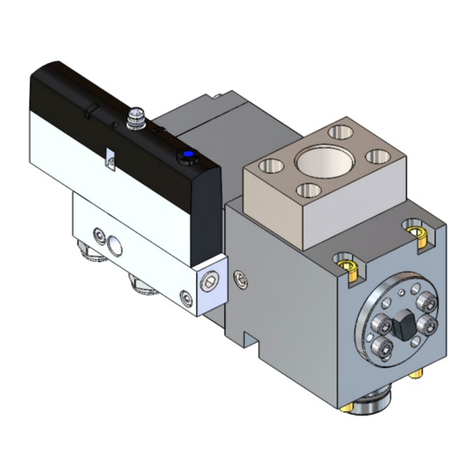
SAMES KREMLIN MINI Series User manual

Index revision : I - November 2018 1 6243
User manual
SAMES KREMLIN SAS - 13, Chemin de Malacher - 38240 MEYLAN - FRANCE
Tel. 33 (0)4 76 41 60 60 - www.sames-kremlin.com
Stainless Steel "MINI" Pneumovalves
DES01691

Index revision : I - November 2018 2 6243
All communication or reproduction of this document, in any form whatsoever and all use or
communication of its contents are forbidden without express written authorisation from
SAMES KREMLIN.
The descriptions and characteristics mentioned in thisdocument are subject tochange without
prior notice.
© SAMES KREMLIN 2002
WARNING : SAMES KREMLIN SAS is registered with the Ministry of Labour as a training insti-
tution.
Throughout the year, our company offers training courses in the operation and
maintenance of your equipment.
A catalogue is available on request. Choose from a wide range of courses to acquire
the skills or knowledge that is required to match your production requirements and
objectives.
Our training courses can be delivered at your site or in the training centre at our Mey-
lan head office.
Training department:
Tel. 33 (0)4 76 41 60 04
E-mail: formation-clie[email protected]
SAMES KREMLIN SAS operating manuals are written in French and translated into English, German, Spanish, Italian
and Portuguese.
The French version is deemed the official text and SAMES KREMLIN will not be liable for the translations into other
languages.

Index revision : 3
Stainless Steel "MINI" Pneumovalves
1. Marking- - - - - - - - - - - - - - - - - - - - - - - - - - - - - - - - - - - - - - - - - - - - - 4
2. General - - - - - - - - - - - - - - - - - - - - - - - - - - - - - - - - - - - - - - - - - - - - 4
3. Characteristics- - - - - - - - - - - - - - - - - - - - - - - - - - - - - - - - - - - - - - - 4
3.1. Pneumovalve Type “G“ . . . . . . . . . . . . . . . . . . . . . . . . . . . . . 4
3.2. Pneumovalve type “RS“ . . . . . . . . . . . . . . . . . . . . . . . . . . . . . 5
4. Operation- - - - - - - - - - - - - - - - - - - - - - - - - - - - - - - - - - - - - - - - - - - 6
5. Installation- - - - - - - - - - - - - - - - - - - - - - - - - - - - - - - - - - - - - - - - - - - 6
5.1. MINI Pneumovalve G (2-way) . . . . . . . . . . . . . . . . . . . . . . . . 6
5.2. RS MINI Pneumovalves (2- or 3-way) . . . . . . . . . . . . . . . . . . 6
5.3. Control Air Circuit . . . . . . . . . . . . . . . . . . . . . . . . . . . . . . . . . . 7
5.4. Product Circuit . . . . . . . . . . . . . . . . . . . . . . . . . . . . . . . . . . . . 7
5.4.1. 2-Way Mini Pneumovalve G. . . . . . . . . . . . . . . . . . . . . . . . . . . . 7
5.4.2. 2- or 3- Way Mini Pneumovalve RS . . . . . . . . . . . . . . . . . . . . . . 7
6. Servicing - - - - - - - - - - - - - - - - - - - - - - - - - - - - - - - - - - - - - - - - - - - - 7
6.1. Maintenance . . . . . . . . . . . . . . . . . . . . . . . . . . . . . . . . . . . . . . 7
6.2. Disassembly . . . . . . . . . . . . . . . . . . . . . . . . . . . . . . . . . . . . . . . 7
6.2.1. Disassembly of the pneumovalves all types excepted the
pneumovalves isocyanate. . . . . . . . . . . . . . . . . . . . . . . . . . . . . . . . . . 7
6.2.2. Disassembly of the isocyanate pneumovalves . . . . . . . . . . . . 8
6.3. Reassembly . . . . . . . . . . . . . . . . . . . . . . . . . . . . . . . . . . . . . . . 9
6.3.1. Reassembly of the pneumovalves all types except the
pneumovalves isocyanate. . . . . . . . . . . . . . . . . . . . . . . . . . . . . . . . . . 9
6.3.2. Reassembly of the isocyanate pneumovalves . . . . . . . . . . . . 9
6.4. Sticking and adjustment of the "screwed" needles" . . . . . 11
7. Problems, Troubleshooting. - - - - - - - - - - - - - - - - - - - - - - - - - - - - - 12
8. Spare Parts - - - - - - - - - - - - - - - - - - - - - - - - - - - - - - - - - - - - - - - - - 13
8.1. MINI Pneumovalve RS (2-ways) . . . . . . . . . . . . . . . . . . . . . 13
8.2. 2-way pneumovalve RS, isocyanate . . . . . . . . . . . . . . . . . 15
8.3. MINI Pneumovalve RS (3-ways) . . . . . . . . . . . . . . . . . . . . . 17
8.4. Pneumovalve (Flowmeter Bypass) . . . . . . . . . . . . . . . . . . . 19
8.5. MINI Pneumovalve G (2-ways) . . . . . . . . . . . . . . . . . . . . . . 21
8.6. Safety pneumovalve . . . . . . . . . . . . . . . . . . . . . . . . . . . . . . 23
8.7. Shunt / safety pneumovalve . . . . . . . . . . . . . . . . . . . . . . . . 24
8.8. 2-way pneumovalve G - isocyanate . . . . . . . . . . . . . . . . . 25
8.9. 3-way pneumovalve G - isocyanate . . . . . . . . . . . . . . . . . 27
8.10. 4-way pneumovalve G - isocyanate . . . . . . . . . . . . . . . . 29
8.11. 2-way pneumovalve D: 7- isocyanate . . . . . . . . . . . . . . 31
8.12. 2-way pneumovalve for block - isocyanate . . . . . . . . . . 33

Index revision : I - November 2018 4 6243
This manual contains links to the following user manuals:
•see RT Nr 6021 for the microvalve.
1. Marking
2. General
These pneumovalves are specially designed for rapid color changing. Product channels are
direct, with no wells or contact with difficult-to-clean surfaces. Air and paint gaskets around the
shaft are compressed by a spring and do not require adjustment or retightening. Materials in
contact with the product withstand all pH levels in paints. These pneumovalves are always of
the "normally closed" type, i.e. they are closed when the APPLICATION side is idle (no control
air). The following variants exist:
•Mini G pneumovalve : 2-way model for fitting in a color change manifold.
•Mini RS pneumovalve :
2- and 3-way models designed to be fitted directly on paint atomizers.
3. Characteristics
3.1. Pneumovalve Type “G“
• Product channel diameter = 5 mm
• Weight (without union): 310 g
• Materials,
•Bodyandhousing
• Needle: polyamide 6
• Shaft: stainless steelAISI 303
• Gasket (air or product):
• Tapered seal: PTFE
• Utilization position: horizontal, vertical or other
• Products: air, water, solvent, paint
• Control air: filtered, dehumidified air at a pressure of 6 bar
• Total response time between energizing the control solenoid
valve and full opening of the Mini pneumovalve (with air
supply hose of dia. 2.7 x 4):
• 50 ms with 0.5 m of hose
• 300 ms with 15 m of hose
• Approx. 1 s with 35 m of hose.
1dia. 32
285 mm
4Product outlet for application
Dossier technique : PV mini
N de SERIE:
II 2 G c T6
DES04403
DES01350
2
1
4

Index revision : I - November 2018 5 6243
3.2. Pneumovalve type “RS“
• Product channel diameter
= 5 mm.
• Weight (without union):
•2-way mini RS 440 g
•3-way mini RS 640 g
•Materials,
• Body and housing: stainless
steel NSU
• Needle: polyamide 6
• Shaft: stainless steelAISI 303
•Gasket
(air or product):
Graphite-loaded teflon
• Tapered seal: PTFE
• Utilization position:
horizontal, vertical or other
• Products: air, water, solvent,
paint
• Control air: filtered and
dehumidifiedairatapressureof
6 bar.
• Total response time between energizing the control solenoid valve and full opening of the
Mini pneumovalve (with air supply hose of dia. 2.7 x 4):
• 50 ms with 0.5 m of hose
• 300 ms with 15 m of hose
• Approx. 1 s with 35 m of hose.
1dia. 32
285 mm
3Product inlet
4Product outlet for application
5Product return
6106 mm
DES01349
1
6
3
5
4
2
1
3
4

Index revision : I - November 2018 6 6243
4. Operation
• In idle mode the Mini pneumovalve is closed. The piston spring 5pushes against the piston
6secured to the shaft 8(or 14) which opens the needle 11 (or 16) for outlet to the
application 12. Product arriving at 1cannot flow to 12.
• With the 3-way pneumovalve, the product flows via the return 15.
• When the control air is pressurized, the piston 6compresses the spring 5driving the shaft 8
(or 14) and the needle 11 (or 16). The product can then flow to 12.
• With the 3-way pneumovalve, the return 15 is closed by the rear end of the needle 16.
•Theshaft8(or 14) is sealed from the air or product by gaskets 3and a tapered seal 2. The
gaskets are compressed by the stuffing box spring 9.
• A venting holebetween these gaskets allows easydetection of aseal breakso thatmixing
of the two fluids can be avoided.
Remarks: For the operation of the pneumovalves (P/N # 910007742, 910008070), see RT Nr 6021
5. Installation
5.1. MINI Pneumovalve G (2-way)
This pneumovalve is secured by 2 screws to a base plate (for 2 or 3 pneumovalves) or a
manifold (for 5, 8 or X pneumovalves).
For special use it can be secured to base plates with RS outlets (see below).
5.2. RS MINI Pneumovalves (2- or 3-way)
This pneumovalve is secured to the front of the atomizer via an RS outlet base plate, in axial,
lateral or offset configuration (see figure) by means of 2 screws.
1
10
16
13
12
8
7
6
5
4
3
2
12
15
1
12
1
14
9
11
DES01694

Index revision : I - November 2018 7 6243
5.3. Control Air Circuit
The control solenoid valve must be 3-way to allow pneumovalve venting in idle mode. A dia.-
2.7 x 4 Rilsan hose must be used to connectthecontrol solenoidvalve tothe Mini pneumovalve.
The 1/8 tapered x dia.-4 elbow union required for the Mini pneumovalve is always delivered
with the product. To reduce the response time of the assembly, place the control solenoid
valve as close as possible to the pneumovalve.
5.4. Product Circuit
5.4.1. 2-Way Mini Pneumovalve G
The product is supplied to the pneumovalve via a 1/8" BSP tapered union (not supplied with the
pneumovalve).
5.4.2. 2- or 3- Way Mini Pneumovalve RS
The product is supplied to the pneumovalve (and the return if fitted) via special SAMES unions.
Unless indicated otherwise, the pneumovalve is delivered with unions for dia. 6 x 8 Rilsan hoses.
Unions for dia. 4 x 6 Rilsan or dia. 4 x 16 and dia. 8 x 20 polyethilene hoses can be delivered as
options. For hoses of other diameters and materials, please contact our technical services.
6. Servicing
6.1. Maintenance
Maintenance is limited to changing the needle or gaskets if sealing is no longer efficient and a
seal cartridge for the isocyanate pneumovalves .
6.2. Disassembly
6.2.1. Disassembly of the pneumovalves all types excepted the pneumovalves isocyanate
1 Remove the pneumovalve from its base plate or manifold.
2 If necessary remove the control air and product hoses.
3 Remove the 2 screws counter-sunk into the metal on the APPLICATION side “12“.
4 Unscrew the needle 11 (or 16).
5 The central part can then be separated. It contains the paint seal assembly comprising a
tapered seal 2and two gaskets 3.
6 To remove the shaft 8(or 14):
• Remove the circlip at the other end of the pneumovalve.
• Remove the plug and piston spring 5then the piston 6and shaft.
• This is only necessary on exceptional occasions to reach the piston seal 7and the air
seal assembly containing the air gasket 3.

Index revision : I - November 2018 8 6243
6.2.2. Disassembly of the isocyanate pneumovalves
Removal of the needle:
•Step 1: Tighten the needle with a vice in order to ovalize it, turn of 90° and to start again
to tighten.
•Step 2: Make lever with a grip to extract it from the axis.
WARNING : Remain straight in order not to fold the part "fir tree".
•Step 3: On a small chuck of drilling machine vertically positioned (not to twist the axis) to
block the part "fir tree" to prevent that the axis turns at the time of the unscrewing of the
nuts of the piston.
•Step 4: Unscrew the cap nut (ref.: X4KEHB003), remove the red plate (Ref.:1410082), the
external circlip (ref.: X4KQNT117), the lock washer (ref.: 900000571), the spring
(Ref.:449089), and the nut M3 (Ref.:X4KEHU003).
•Step 5: Remove the pneumovalve from the chuck, remove the flat washer
(Ref.:X4KDZU003) and the sealing ring (ref.: J4BRND032) (fold it with a grip and unscrew).
•Step 6: Disunite the axis of the piston, the piston is stuck on the axis by the joint-sealing
product, to separate them, install the pneumovalve on the block support (ref.: 1315253)
and give a blow of mallet on the axis.
•Step 7: Extract the piston unit, the sealing ring (ref.: J4BRND032) (fold it with a grip and
unscrew), the washer (Ref.:1412147), if necessary install the axis on the chuck to unscrew
the nut M3 (ref.: X4KEHU003).
•Step 8: Remove the axis, extract the two screws milled (Ref.:X4EVSF123) to remove the
stuffing box from the body, leave the spring bushing (ref.: 449093) and the drain washer
(ref.:749985), the spring (ref.: 449095), the equipped seal cartridge (ref.: 749987), the ring
Teflon (ref.: 749986) and biconical sealing ring (ref.: 441117).
•Step 9: If necessary to replace the seal of piston (ref.: 449091), for that, to block the body
of piston on a vice equipped with jaws with vertical V-shaped grooves or a standard grip
"multi-grip" (to protect the nozzles not to stripe the part), unscrew the nut, remove the
damage seal, clean the body of piston and the nut, to plate it well on the body of piston,
put a drop of loctite "oléoétanche 542" on the bottom of the threading of the piston (with
screwing, the nut will distribute the product on the seal), screw the nut side chamfer resting
against the seal and tighten moderately from 1/4 to 1/2 turn (too much to tighten, the
seal becomes deformed). Wipe the excess of product.
•Step 10: Clean all the reusable parts, pass the die M3 on the threading of the axis if this one
is reusable (it should neither be striped, nor twisted).

Index revision : I - November 2018 9 6243
6.3. Reassembly
6.3.1. Reassembly of the pneumovalves all types except the pneumovalves isocyanate
In reverse order, observing the following precautions:
1 Install in the stuffing box body: the conical seal, the seal cartridge and the metallic ring
respecting their assembling order.
2 Compress the stuffing box spring 9(by pushing the parts forming the pneumovalve body
by hand) while screwing the needle 11 (or 16).
3 Screw both assembly screws simultaneously and tighten them firmly.
Note 1: It is normal to find a regular, ring-shaped notch on the cone of the needle. This area of
caulking is useful for providing a good seal. However, if it is irregular or has stripes cut into it, the
needle may no longer be sealed and needs to be replaced.
Note 2: An oil-resistant cyanoacrylate sealant (Loctite) is used to produce the seal between the
piston 6 and the shaft 8 (or 14). Only dismantle these parts if absolutely necessary, and renew
this seal when refitting.
Note 3: Before replacing the gaskets 3 or the piston seal 7, soak the replacement parts with a
few drops of pure vaseline oil.
Note 4: If the gaskets, piston seal or needle are changed, "break in" the refitted pneumovalve
by carrying out 500 cycles without product so that:
• The needle is caulked,
• The gaskets are compacted and sit correctly,
• The piston seal is worn in.
6.3.2. Reassembly of the isocyanate pneumovalves
Assembling and Caulking of the biconical sealing ring (Ref.: 441117)
•Step 1: Soak the rings at least 30 minutes in vaseline oil, leave a ring vaseline oil and put it
in the body of piston (ref.: 434987),
•Step 2: Put in place above the spring bushing (Ref.:449093) and to caulk slightly on the
spring bushing (Ref.:449093) (in general a small blow is enough, if not a part of the ring will
pass side piston.)
WARNING : The caulking of the ring will be made without the axis of piston in order to obtain a
light tightening of the ring which will ensure the sealing on the axis.
•Step 3: In the body of stuffing box (Ref.:1312749), install the tapered seal (Ref.:749986) and
the equipped seal cartridge (Ref.:749987) (take care to the direction of assembling of the
equipped seal cartridge).
•Step 4: Put in place the drain washer (Ref.:749985) then the spring (Ref.:449095).
•Step 5: Secure the body of stuffing box on the body of pneumovanne with the two screws
(F/90 HC 4x20 ref.: X4EVSF123).
Assembly of the axis of the piston in the body
•Step 6: Block the axis of piston side "fir tree" on a small chuck of drilling machine positioned
vertically (not to twist the axis), introduce the pneumovalve side stuffing box, and screw it
on the level of the sealing ring (ref.: 441117 (to avoid withdrawing it).
•Step 7:Push completely the pneumovalve until it stops on the chuck.
•Step 8: Clean the axis (threading recover a little trimming and vaseline).Screw and block
the nut (ref.: X4KEHU003) completely.
Note: the axis should not turn in the chuck.

Index revision : I - November 2018 10 6243
•Step 9: Install the washer (Ref.: 1412147) and the sealing ring (Ref.: J4BRND032).
•Step 10: Deposit and distribute a half drip of loctite "oléoétanche 542" between the seal-
ing ring (ref.: J4BRND032) and the axis.
•Step 11: Assemble the piston unit, pay attention that the lip of the seal is not turned over,
for that, to exert a rotational movement while entering the body.
•Step 12: Install the second sealing ring (ref.: J4BRND032), put in place the flat washer (ref.:
X4KDZU003), screw and block the nut (ref.: X4KEHU003).
WARNING : Before installing the needle, it is necessary to carry out a pre control of sealing of
the sealing ring (ref.: 441117) (to make sure that caulking is good) and also the seal of pis-
ton (ref.: 449091).
•Step 13: Remove the pneumovalve from the chuck, lubricate the interior of the body by
depositing 3 to 4 vaseline oil drops.
•Step 14: Putthe spring, installthe lock washer (Ref.:900000571) (shoulder inside), close with
the internal circlip (Ref.:X4KQNT117) (if possible, make the assembly on a press in order to
compress the spring and to facilitate the assembly of the ring).
•Step 15: Pilot between 5 and 6 bar.
Result of the test:
• For the piston seal (ref.: 449091), not of audible leakage with approximately 30 to 50 cen-
timetres of the ear.
• For the sealing ring (Ref.: 441117), put a water drop in the ddrain hole of the stuffing box
body (Ref.:1312749), there should not be bubble.
• Switch off the air.
•Step 16: Assemble the plate of visualization (ref.: 1410082) (P7 marking must be visible).
•Step 17: Screw and block slightly the cap nut (Ref.:X4KEHB003) ) if necessary lock the axis
on the chuck
Assembly of the needle:
• Fix the needle which will be positioned until it stops against the shoulder of the axis.

Index revision : I - November 2018 11 6243
6.4. Sticking and adjustment of the "screwed" needles"
Material necessary:
•Step 1: Temporarily, maintain the stuffing box body on the body with two screws to leave
free the threading of the axis.
•Step 2: Clean and degrease carefully the threaded part of the axis and the tapping of the
needle with a solvent, wipe to dry the parts with a clean rag.
•Step 3: Deposit using the glue gun, a drop of glue inside the needle at the beginning of
the tapping.
•Step 4: Screw the needle.
•Step 5: Check the dimension according to the table below between the back of the nee-
dle and the stuffing box body. Let dry the glue approximately 8 hours at the free air (or 3
hours under 40°C).
•Step 6: After drying, if necessary remove the pad of glue. Remove the two screws.
Nota : the pad guarantees that the glue is well distributed.
Adjustment of the needles:
Part number Description
H2CPAL062 Glue DP460
W1SBPM083 Mixing nozzle
W1SPML084 Glue gun
W1SBPM095 Blue needle
Part number
of the Needles Positioning dimensions of the needle
458804 4 mm
459159 4 mm
1516999 4 mm
458816 2 mm
1519550 2 mm
459153 18 mm between the end of the needle and the stuffing
box body.
1521947 In stop against the axis
1521483 In stop against the axis

Index revision : I - November 2018 12 6243
7. Problems, Troubleshooting.
Symptoms Causes Remedies
The pneumovalve does not
open
(the operating indicator
does not remain in out posi-
tion at the rear of the pneu-
movalve).
The control air does not
arrive at the pneumovalve.
Check the control circuit
(control hose folded or dis-
connected).
The control pressure is less
than 5 bar (72,5 Psi). Increase the network pres-
sure.
The needle control rod is
jammed. If there is a leak at
the gaskets, the paint may
dry if the gun is not used for
some time preventing the
needle rod from moving.
Check if any product has
flowed through the venting
hole.
If this is the case, replace the
pneumovalve.
The piston seal is damaged.
If this seal leaks, pressure
cannot build up in the con-
trol chamber.
Remove the pneumovalve.
Check that the needle can
recede by pushing the end
of it with a flat tool. If it does
not operate correctly,
replace the pneumovalve.
The pneumovalve does not
close.
The control air circuit
remains pressurized.
The control solenoid valve is
not operating correctly. The
air cannot be drained.
The return spring is broken.
After disassembling the
pneumovalve, exert a pres-
sure on the end of the nee-
dle. Lack of resistance is a
sign that the spring is worn. If
so, replace the pneumov-
alve.
The needle control rod is
jammed.
Check that the indicator
can move out by pressing
on the end of it with a flat
tool.
If it does not operate cor-
rectly, replace the pneumo-
valve.
The pneumovalve no longer
acts correctly as a valve.
If the pneumovalve cannot
be closed, the needle does
not exert enough pressure
on its seat, resulting in prod-
uct leakage.
See previous symptom.
The needle is faulty.
Remove the pneumovalve.
Check visually for scratches
or faults on the needle. If
faults can be seen, change
the needle.
Check for foreign matter on
the needle bearing. Clean as necessary.

Index revision : I - November 2018 13 6243
8. Spare Parts
8.1. MINI Pneumovalve RS (2-ways)
27
7
8
9
2
17
18
22
418 21
6
16
3
19
12
5
10
1
13
11
5
15
14
26
20
20
24
26
25
23
DES01662

Index revision : I - November 2018 14 6243
Item Part number Description Qty Unit of sale
458804 2-way pneumovalve RS 1 1
1 434986 2-way stuffing box body 1 1
2 434987 Piston body, stainless steel M 5 1 1
3 437534 Block body, minivalve RS, stainless steel 1 1
4 438460 Mini die, stainless steel 1 1
5 441117 Biconical sealing ring 3 5
6 449085 2-way needle 1 1
7 900000571 Lock washer 1 1
8 449089 Piston spring 1 1
9 449091 Piston seal 1 1
10 449092 Drain washer 1 1
11 449093 Spring bushing 1 1
12 449094 Tapered seal 1 1
13 449095 Stuffing box spring 1 1
14 740392 Piston 1 1
15 740393 Nut 1 1
16 449084 2-way piston shaft 1 1
17 F6RLCS270 Male elbow 1 1
18 J3TTCN009 O ring 2 5
19 J3TTCN011 O ring 1 2
20 J4BRND032 Sealing ring 2 1
21 X4FVSY125 Screw, CHC M 4 x 30, s/s 316 4 1
22 X4FVSY073 Screw, CHC M 3 x 25, s/s 316 2 1
23 X4KDVX003 Fan washer, AZ 3 s/s 316 1 1
24 X4KDZU003 Flat washer, Z Ø 3 x 6 s/s 316 1 1
25 X4KEHB003 Cap nut, dia. M 3 s/s 316 1 1
26 X4KEHU003 H nut, dia. M 3 s/s 316 2 1
27 X4KQNT117 Internal circlip 1 1
- 455437 Repair kit - -

Index revision : I - November 2018 15 6243
8.2. 2-way pneumovalve RS, isocyanate
DES04619
1
2
3
4
5
6
7
8
9
10
11
12
13
14
15
16
17
18
19
20
21
19 22
23
24
2
25
26
27
25
28

Index revision : I - November 2018 16 6243
Item Part number Description Qty Unit of sale
854493 2-way pneumovalve RS, isocyanate 1 1
1 640732 Plate, visualization 1 1
2X4KEHU003 H nut, dia. M 3 s/s 316 2 1
3X4KDZU003 Flat washer, Z Ø 3 x 6 s/s 316 1 1
4 900000571 Lock washer 1 1
5 449089 Piston spring 1 1
6 449091 Piston seal 1 1
7 740393 Nut 1 1
8 441117 Biconical sealing ring 1 5
9 449093 Spring bushing 1 1
10 449095 Stuffing box spring 1 1
11 749985 Drain washer 1 1
12 749987 Equipped seal cartridge 1 1
13 J3TTCN011 O ring 1 2
14 749986 Tapered seal 1 1
15 437534 Block body, minivalve RS, stainless steel 1 1
16 X4FVSY125 Screw, CHC M 4 x 30, s/s 316 2 1
17 449085 2-way needle 1 1
18 749983 2-way piston shaft 1 1
19 J3TTCN009 O ring 2 5
20 438460 Mini die, stainless steel 1 1
21 X4FVSY073 Screw, CHC M 3 x 25, s/s 316 2 1
22 732335 2-way stuffing box body 1 1
23 F6RLCS270 Male elbow 1 1
24 434987 Piston body, stainless steel M 5 1 1
25 J4BRND032 Sealing ring 2 1
26 740392 Piston 1 1
28 X4KEHB003 Cap nut, dia. M 3 s/s 316 1 1
27 X4KQNT117 Internal circlip 1 1

Index revision : I - November 2018 17 6243
8.3. MINI Pneumovalve RS (3-ways)
8
20
27
DES01663
25
23
26
24
15
9
1
17
14
3
18
18
21
4
19
222 6
18
4
18
13
7
12
5
11
516
10
26
20

Index revision : I - November 2018 18 6243
Item Part number Description Qty Unit of
sale
458816 3-way pneumovalve RS 1 1
1 434987 Piston body 1 1
2 437534 Block body, minivalve RS, stainless steel 1 1
3 438256 3-way stuffing box body 1 1
4 438460 Mini die, stainless steel 2 1
5 441117 Biconical sealing ring 3 5
6 449087 3-way needle 1 1
7 449086 3-way piston shaft 1 1
8 449088 Lock washer 1 1
9 449089 Piston spring 1 1
10 449091 Piston seal 1 1
11 449092 Drain washer 1 1
12 449093 Spring bushing 1 1
13 449094 Tapered seal 1 1
14 449095 Stuffing box spring 1 1
15 740392 Piston 1 1
16 740393 Nut, M 12 1 1
17 F6RLCS204 Male elbow 1 1
18 J3TTCN009 O ring 4 5
19 J3TTCN011 O ring 1 2
20 J4BRND032 Sealing ring 2 1
21 X4FVSY129 Screw, CHC M 4 x 50, s/s 316 4 1
22 X4FVSY073 Screw, CHC M 3 x 25, s/s 316 2 1
23 X4KDVX003 Fan washer, AZ 3 s/s 316 1 1
24 X4KDZU003 Flat washer, Z Ø 3 x 6 s/s 316 1 1
25 X4KEHB003 Cap nut, dia. M 3 s/s 316 1 1
26 X4KEHU003 H nut, dia. M 3 s/s 316 2 1
27 X4KQNT117 Internal circlip 1 1
- 455437 Repair kit - -

Index revision : I - November 2018 19 6243
8.4. Pneumovalve (Flowmeter Bypass)
6
7
25
DES01664
13
2
3
2
1
2
4
2
2
1
8
18
24
8
14
3
10
12
9
17
3
11
520 16
1
9
2
4
1
15

Index revision : I - November 2018 20 6243
Item Part number Description Qty Unit of sale
459153 Pneumovalve (flowmeter bypass) 1 1
1 434987 Piston body, stainless steel M 5 1 1
2 438781 Valve base plate, flowmeter bypass 1 1
3 441117 Biconical sealing ring 3 5
4 449086 3-way piston shaft 1 1
5 449087 3-way needle 1 1
6 449088 Lock washer 1 1
7 449089 Piston spring 1 1
8 449091 Piston seal 1 1
9 449092 Drain washer 1 1
10 449093 Spring bushing 1 1
11 449094 Tapered seal 1 1
12 449095 Stuffing box spring 1 1
13 740392 Piston 1 1
14 740393 Nut 1 1
15 F6RLCS204 Male elbow 1 1
16 J3TTCN009 O ring 1 5
17 J3TTCN011 O ring 1 2
18 J4BRND032 Sealing ring 2 10
19 X2BVCB125 Screw, CHC M4 X 30 4 1
20 X3AVSY126 Screw, CHC M4 X 35 2 1
21 X4KDVX003 Fan washer, AZ 3 s/s 316 1 1
22 X4KDZU003 Flat washer, Z Ø 3 x 6 s/s 316 1 1
23 X4KEHB003 Cap nut, dia. M 3 s/s 316 1 1
24 X4KEHU003 H nut, dia. M 3 s/s 316 2 1
25 X4KQNT117 Internal circlip 1 1
- 455437 Repair kit - -
This manual suits for next models
2
Table of contents
Other SAMES KREMLIN Control Unit manuals
Popular Control Unit manuals by other brands

OSF
OSF POOLcontrol-45 exclusiv Installation and operating instructions

MTT
MTT MS3765 user manual

M-system
M-system 61F instruction manual

EOS
EOS ECON 09 Installation and user guide

DEMA
DEMA Chemaster DM-813-PLLL-1T installation instructions

Allmess
Allmess ITRON EquaScan pMIURF Assembly and Programming Instructions

Lenze
Lenze SMVector reference guide

Newhaven Display International
Newhaven Display International NHD user guide

Grundig
Grundig GSS HAMS 400 Assembly instruction

EWM
EWM T4.06-Tetrix AC/DC Smart 2.0 operating instructions

Digi
Digi XBee user guide

Parker
Parker Sporlan SD-114 Installation and servicing instructions