Samlexpower ADJ-28 User manual

28"
Adjustable
Solar Tilt
Mount
ADJ-28
Please read this
manual BEFORE
installing your
solar tilt mount
Owner's
Manual

2 | SAMLEX AMERICA INC.
SECTION 1 | Introduction
Mounting your solar panel inclined to an optimized angle with respect to the horizontal
axis can lead to increased annual collection of sunlight. Depending on the location and
time of the year, this could lead to up to 50% more solar energy collection compared to
horizontally mounted panels. Typically, for optimal annual performance, the solar panel
should be tilted at an angle equal to 0.9 times the latitude of the location with respect
to the horizontal. For optimal summer performance, the solar panel should be tilted to
an angle equal to latitude – 15 degrees and optimal winter performance the solar panel
should be tilted to angle equal to latitude + 15 degrees with respect to the horizontal.
The ADJ-28 Tilt Mount kit includes 4 Nos. sturdy 28” Aluminum mounting rails, 2 Nos.
14” Aluminum brackets (Fig. 1) and stainless steel hardware required to securely fasten
a solar panel to the roof of your Recreational Vehicle (RV) or any other at surface. The
inclination of the solar panel can be adjusted to a desired angle with respect to the
horizontal axis.
Fig.1. ADJ-28 Tilt Mount
........................................................................
1
...........................................................................
...........................................................................
..................................................................
1, 2 28” Mounting Rail (for base support)
3, 4 28” Mounting Rail (for supporting solar panel)
5, 6 14” Aluminum Bracket for setting tilt angle
7.1 to 7.6 Carriage bolts
8.1 to 8.6 Wing nuts
7.6
7.5
7.4
7.3
7.2
7.1
4
5
2
3
8.3
8.2
8.1
8.6
8.4
8.5

SECTION 2 | Components & Required Tools
List of Parts (included in the kit)
Part Description
Quantity Illustration
28” Aluminum mounting rail for base support 2Fig. 1
28” Aluminum mounting rail for supporting
solar panel 2Fig. 1
14” Aluminum bracket for setting tilt angle 2Fig. 1
¼” - 20 x 1” stainless steel carriage bolts 6Fig. 1
¼” - 20 stainless steel wing nuts 6Fig. 1
Stainless steel serrated ange bolt ¼” - 20 x ¾" 4Fig. 2
Stainless steel nylon insert locknut, ¼” 4Fig. 2
Stainless steel at washer, ¼” - 20 8Fig. 2
Well nut-nut thread:
¼” - 20, length: 1”, shank diametre: ½” 4Fig. 8
Stainless steel serrated ange bolt, ¼”- 20 x 1¼” 4Fig. 8
Required Tools (not included in the kit)
• 7/16” wrench
• 3/8” wrench
• Hand Drill
• ½” drill bit
• Pliers
• Punch or Awl

4 | SAMLEX AMERICA INC.
SECTION 3 | Installation
Pre-installation
With the incidence of sunlight on all photovoltaic modules, a voltage appears at the
output terminals of the photovoltaic module turning it into a live power source. To
avoid a shock hazard make sure the solar module is covered with an opaque (dark)
material such as paper / cloth.
Stainless Steel can be subject to a process called “thread galling” in which bolts can twist
off and/or the bolt threads seize to the nut’s thread. Apply anti-galling lubricant avail-
able at most hardware or auto-parts stores to all the stainless steel fasteners before in-
stallation. If anti-galling lubricant is not available, any standard lubricant will minimize
the occurrence of “thread galling”.
Well Nut For Anchoring 28" Base Support Mounting
Rails To The RV Roof Or Flat Surface
A Well-Nut is a bushing of tough neoprene rubber with a ange at the top end and a
captive brass nut mounted within the bore at the bottom end (Fig. 2). This is used to
anchor the 28" base support mounting rails (1, 2 of Fig.1) on to the roof of the RV or to
other at surface. Typical installation is shown in Figs 3 to 6. Tightening a conventional
machine bolt or screw engages the captive nut thereby causing the bushing to expand
outwards. This fastens securely to thinner RV roofs by bulging up and against the bot-
tom surface of the roof (Fig. 5). If used in a blind hole in a solid surface material, the
rubber will expand outwards to create a secure fastening (Fig. 6). The neoprene and
brass resist most environmental conditions. Additionally, the Well-Nut seals the drilled
hole effectively against air and liquid leakage.
ange
1/2” diameter
1/4” captive brass nut
Fig. 2. Construction of a Well Nut

SECTION 3 | Installation
Typical Installation Of A Well-Nut
Installation Procedure
Determine the position of the solar panel on the RV roof or at surface. While position-
ing panels, avoid shading of the solar panel by neighboring obstacles such as vents, air-
conditioners, TV antennas etc. As far as possible, position the panels to minimize wiring
distance between the solar panel and the charge controller. Place the panel at least 8-10
inches away from the RV roof edges and leave sufcient space to walk around the panel
and access the mounting hardware.
Make sure the thickness of the roof at the installation location is at least ½” thick and
the material is strong enough to provide mechanical support to the solar panel and
Fig. 3. Well-Nut is inserted
into a pre-drilled hole with
its ange against the outer
surface. There is no need for
access to the
inner side.
RV Roong
Material
Well Nut
1/4”-20 x 11/4”
Serrated
Flange Bolt
Mounting
Rail
Captive
Brass Nut
Fig. 4. The 28" mounting
rail is placed against the
ange of the Well-Nut and
is secured by the 1/4"-20 x
11/4" serrated ange bolt
engaging the captive brass
nut.
Fig. 5. As the bolt is
tightened, the neoprene
body of the Well-Nut is
compressed and expanded,
forcing it tightly into the
bolt's threads and against
the inner surface of the
thin RV roof material.
Fig. 6. Installed in a blind
hole in a solid material,
the body of the Well-Nut
expands tightly against
the walls of the hole,
effecting a secure,
dependable fastening.

6 | SAMLEX AMERICA INC.
mounting hardware against possible wind loading. Place the panel length-wise to
reduce the effects of wind loading on the RV.
The slots on the mounting rails are sized to accept the ¼” hardware supplied with
the unit.
Fixing The Solar Panel To The Mounting Rails
1. The solar panel frame comes with pre-cut holes to accept external mounting
hardware. Identify these holes.
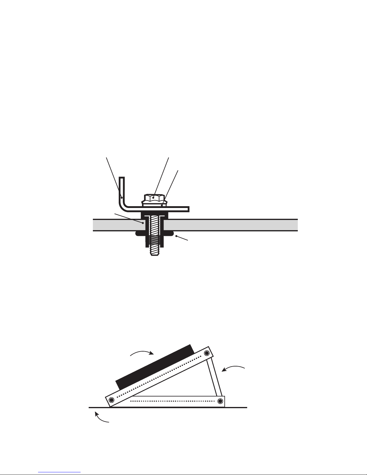
Fig. 7. Attaching Solar Panel to 28” Mounting Rail
2. Fix one pair of 28” mounting rails (3, 4 of Fig.1) to the shorter sides of the solar
panel frame using the slotted opening and the ¼”-20 x ¾" Flange Bolt, Nylon Lock-
nut and at washer (Fig. 7). Using a 7/16” wrench, tighten the nuts to secure the
mounting brackets to the PV panel. Recommended tightening torque is 15 lbs.
3. Attach the second pair of 28” mounting rails (1, 2 of Fig.1) to the rst pair of
mounting rails at one end using the wing nut and the ¼”-20 x 1" carriage bolt, so
that it pivots at one end (Point A in Fig. 9).
Anchoring 28" base support rails (1, 2 of Fig.1) to the RV roof or at
surface with the help of Well-Nuts
4. Position the second pair of 28" mounting rails (1, 2 of Fig.1) on the RV roof or at
surface at the desired location and mark two sets of mounting hole positions on
each 28” rail. It is desirable to have the mounting holes located as close to the
extremities of the 28” mounting rails (1, 2 of Fig.1) as possible.
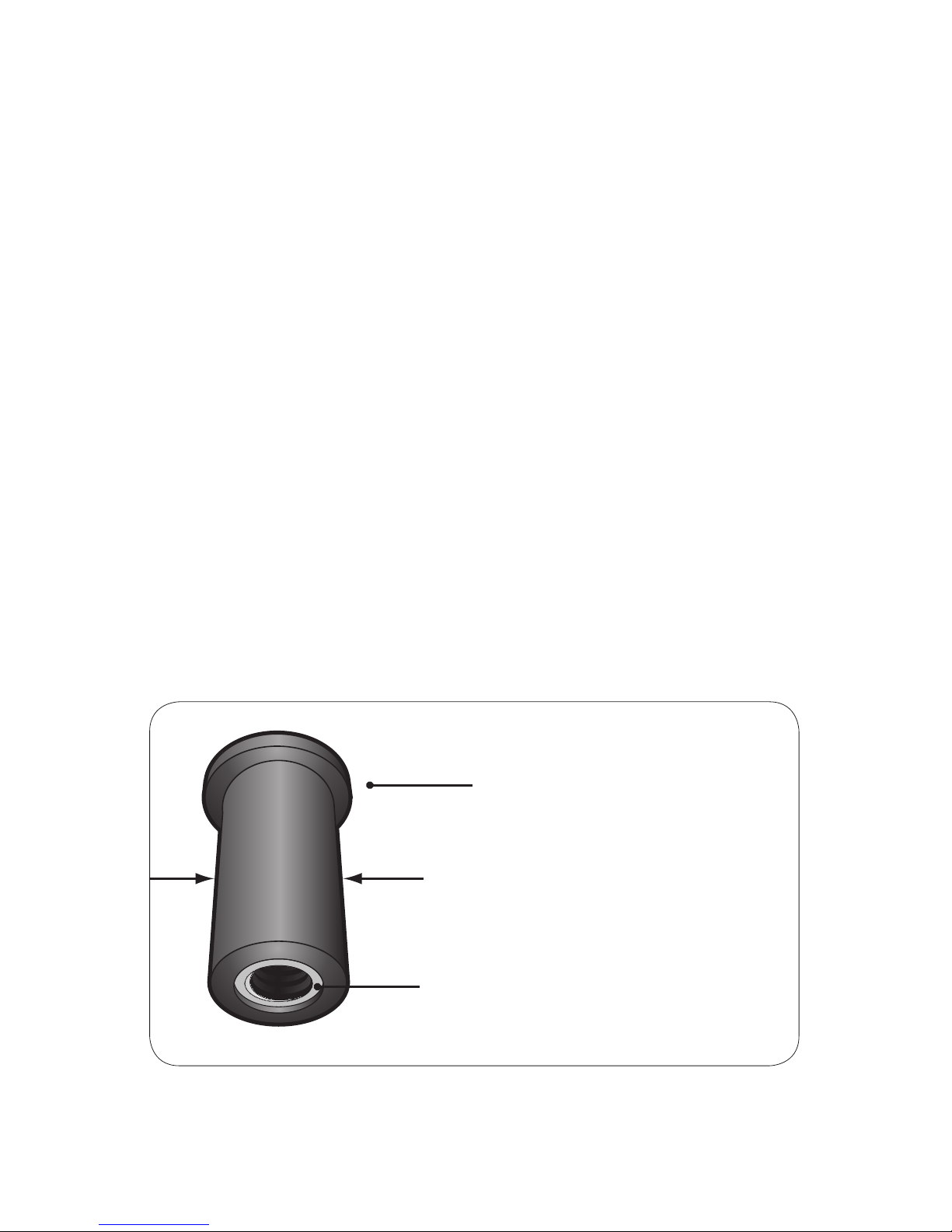
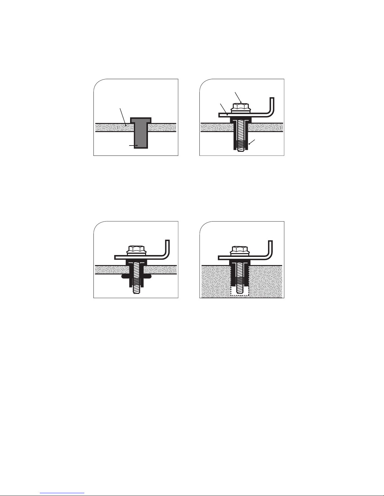
5. To install the Well-Nuts to anchor the two base support mounting rails (1, 2 of
Fig.1), drill holes 1¼” deep at the marked positions using a ½” size drill bit. Make
sure that drilling does not interfere with pre-existing wiring installations.
SECTION 3 | Installation
Solar module
1/4” ange bolt
1/4” at washer
1/4” at washer
1/4” locknut
28 “ mounting rail
(3, 4 of Fig.1)
Aluminium frame
of the solar panel

6. Apply silicone or any appropriate sealant recommended by your RV dealer to the
drilled holes for water-proong.
7. Insert the ¼” Well nut into the drilled holes so that only the ange section remains
above the roof surface (Fig. 3).
8. Fasten the base support mounting rails (1, 2 of Fig.1) to the roof surface by insert-
ing the ¼ x1¼” serrated ange bolt into the Well-Nut. Tighten using a 3/8” wrench
to a recommended torque of 15 lbs. When the serrated ange bolt is screwed into
the Well-Nut, the material surrounding the well nut bulges slightly securing the
structure to the RV roof (Fig. 5, Fig. 8).
Fig. 8 Attaching 28” base support mounting rails
(1, 2 of Fig.1) to the RV roof or other at surface
Setting The Tilt Angle
9. Fix the 14” Aluminum brackets to the free ends of the mounting rail pairs as shown
in Figure 9 using the ¼”-20 x 1" carriage bolts and the ¼” wing nuts to obtain the
desired tilt angle (Point B and Point C in Fig. 9).
Fig. 9 Tilt-up position (Side view)
SECTION 3 | Installation
Rubber bushing material expands
when bolt is tightened to securely
anchor hardware
¼”- 20 x 1¼” ange bolt
¼” at washer
Well-Nut
28” mounting rail
Point B
Point CPoint A
Solar Panel
14” Aluminum Bracket
RV Roof

8 | SAMLEX AMERICA INC.
SECTION 3 | Installation
10. Fig. 9 corresponds to one possible tilt-angle. Other tilt-angles maybe possible by
using different hole combinations.
Travelling mode
11. The mounting hardware should be connected in the tilted position only when the
RV is stationary. When the RV is in motion, the mounting hardware should be in
the at mount position.
12. In order to do this remove the ¼”-20 x 1" carriage bolt carriage bolts by loosening
the ¼” wing nuts at points B and C (Fig. 9).
13. Lower the 28” mounting rails and the 14” brackets so that the square holes of
each set of the mounting rails and brackets align with each other and the solar
panel is at (Fig. 10).
14. Using the ¼”- 20 x 1" carriage bolts and the ¼” wing nuts, secure the structure in
this position (Fig. 10).
Fig. 10 Travelling Mode
Point C
Point A
Point B
Solar Panel
28” Mounting Rail
28” Mounting Rail
RV Roof
SAMLEX AMERICA BATTERY CAR BATTERIES
Table of contents
Other Samlexpower Solar Panel manuals
Popular Solar Panel manuals by other brands

STATCON ENERGIAA
STATCON ENERGIAA SEOG Series product manual

LG
LG MonoX ACe troubleshooting guide

ferolli
ferolli ECOTOP H2 manual

vikram solar
vikram solar SOMERA VSMD.72 Series installation manual

Southwest Windpower
Southwest Windpower Skystream Hybrid 6 installation manual

solarwatt
solarwatt Vision 60P style installation instructions