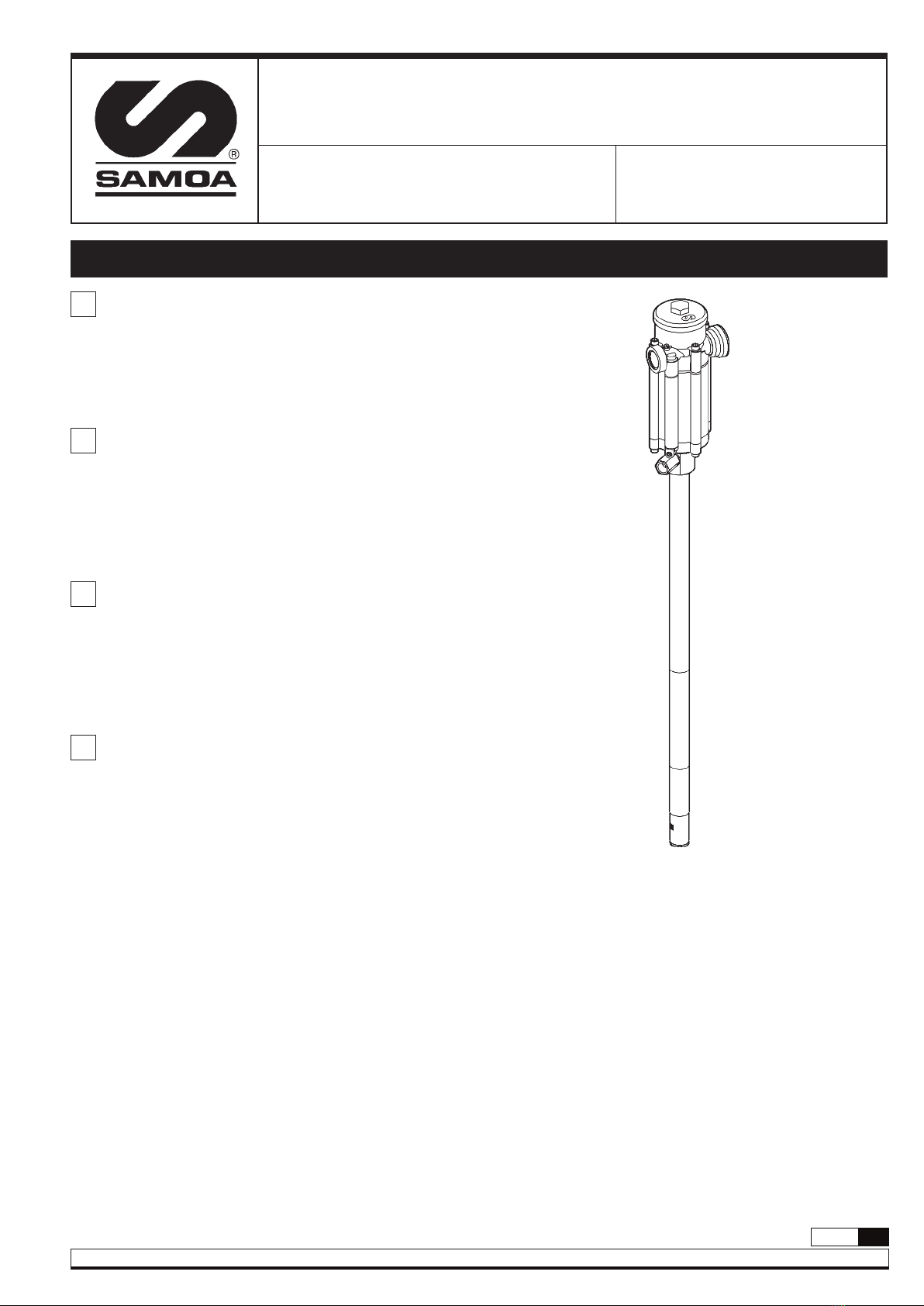
Samoa 402000 Operating manual
Other Samoa Water Pump manuals

Samoa
Samoa LARIUS SIRIO 60:1 Operating instructions

Samoa
Samoa LARIUS THOR Operating instructions

Samoa
Samoa 561610 Operating manual

Samoa
Samoa LARIUS VEGA 34:1 Operating instructions

Samoa
Samoa 300 006 How to use

Samoa
Samoa LARIUS 4 Operating instructions

Samoa
Samoa Larius SUPER NOVA 45:1 Operating instructions

Samoa
Samoa PM100 Operating manual

Samoa
Samoa LARIUS VEGA 34:1 Operating instructions

Samoa
Samoa 536010 Operating manual

Samoa
Samoa 157 000 Troubleshooting guide

Samoa
Samoa LARIUS MINIPEGASO Operating instructions

Samoa
Samoa PM35 Operating manual

Samoa
Samoa 533911 Operating manual

Samoa
Samoa 560 230 How to use

Samoa
Samoa Larius GHIBLI 26:1 EXT Operating instructions

Samoa
Samoa LARIUS GHIBLI 24:1 Operating instructions

Samoa
Samoa 537 130 Operating manual

Samoa
Samoa Larius Dali Liner Plus Series Operating instructions

Samoa
Samoa Larius SUPER NOVA 68:1 Operating instructions


Popular Water Pump manuals by other brands

Watershed Innovations
Watershed Innovations HYDRAPUMP SMART FLEX Instructional manual

Graco
Graco Modu-Flo AL-5M instructions

Messner
Messner MultiSystem MPF 3000 operating instructions

Xylem
Xylem Bell & Gossett WEHT0311M Installation, operation and maintenance instructions

WilTec
WilTec 50739 Operation manual

Franklin Electric
Franklin Electric Little Giant 555702 HRK-360S instruction sheet

Ingersoll-Rand
Ingersoll-Rand PD02P Series Operator's manual

VS
VS ZJ Series Operating instruction

Flotec
Flotec FPZS50RP owner's manual

SKF
SKF Lincoln FlowMaster II User and maintenance instructions

Xylem
Xylem Lowara LSB Series Installation, operation and maintenance instructions

Water
Water Duro Pumps DCJ500 Operating & installation instructions

Action
Action P490 Operating instructions & parts manual

Flo King
Flo King Permacore Reusable Carbon Bag Disassembly. & Cleaning Instructions

ARO
ARO ARO PD15P-X Operator's manual

Pumptec
Pumptec 112V Series Operating instructions and parts manual

Virax
Virax 262070 user manual

Neptun
Neptun NPHW 5500 operating instructions