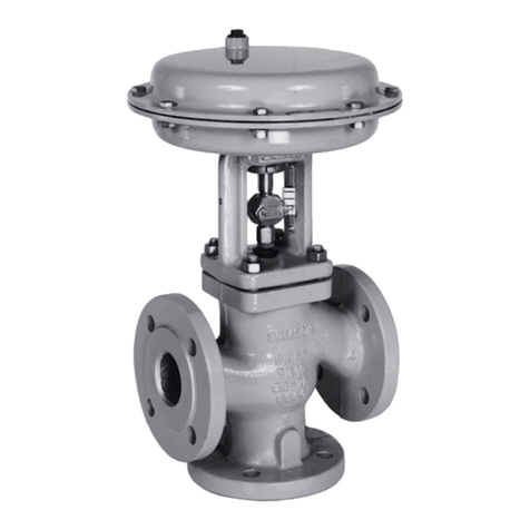
Samson 3253 Setup guide

Translation of original instructions
EB 8055 EN
Edition January 2021
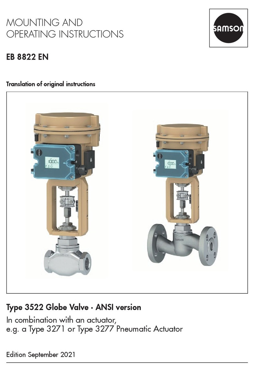
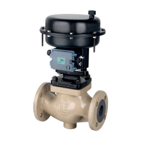
Type3253 Valve · DIN version
In combination with an actuator,
e.g. a Type3271 or Type3277 Pneumatic Actuator

Definition of signal words
Hazardous situations which, if not avoided,
will result in death or serious injury
Hazardous situations which, if not avoided,
could result in death or serious injury
Property damage message or malfunction
Additional information
Recommended action
DANGER
!
WARNING
!
NOTICE
!
Note
Tip
EB 8055 EN
Note on these mounting and operating instructions
These mounting and operating instructions assist you in mounting and operating the device
safely. The instructions are binding for handling SAMSON devices. The images shown in
these instructions are for illustration purposes only. The actual product may vary.
ÎFor the safe and proper use of these instructions, read them carefully and keep them for
later reference.
ÎIf you have any questions about these instructions, contact SAMSON‘s After-sales Service
(aftersalesservice@samsongroup.com).
Documents relating to the device, such as the mounting and operating
instructions, are available on our website at www.samsongroup.com >
Service & Support > Downloads > Documentation.

Contents
EB 8055 EN
1 Safety instructions and measures ................................................................1-1
1.1 Notes on possible severe personal injury ......................................................1-4
1.2 Notes on possible personal injury ................................................................1-5
1.3 Notes on possible property damage.............................................................1-6
1.4 Notes on the use of an RFID tag ...................................................................1-7
1.5 Warnings on the device...............................................................................1-8
2 Markings on the device ..............................................................................2-1
2.1 Valve nameplate .........................................................................................2-1
2.2 Actuator nameplate.....................................................................................2-2
2.3 Material identication number .....................................................................2-2
2.4 Label when an adjustable packing is installed ...............................................2-2
2.5 Optional RFID tag.......................................................................................2-2
3 Design and principle of operation ...............................................................3-1
3.1 Fail-safe positions .......................................................................................3-1
3.2 Versions .....................................................................................................3-3
3.3 Additional ttings........................................................................................3-3
3.4 Accessories ................................................................................................3-4
3.5 Technical data ............................................................................................3-4
4 Shipment and on-site transport ...................................................................4-1
4.1 Accepting the delivered goods .....................................................................4-1
4.2 Removing the packaging from the valve........................................................4-1
4.3 Transporting and lifting the valve..................................................................4-1
4.3.1 Transporting the valve .................................................................................4-2
4.3.2 Lifting the valve...........................................................................................4-3
4.4 Storing the valve.........................................................................................4-4
5 Installation.................................................................................................5-1
5.1 Installation conditions..................................................................................5-1
5.2 Preparation for installation...........................................................................5-3
5.3 Mounting the device....................................................................................5-3
5.3.1 Mounting the external anti-rotation xture.....................................................5-4
5.3.2 Mounting the actuator onto the valve..........................................................5-14
5.3.3 Installing the valve into the pipeline ............................................................5-16
5.4 Testing the installed valve...........................................................................5-16
5.4.1 Leak test...................................................................................................5-17
5.4.2 Travel motion............................................................................................5-18
5.4.3 Fail-safe position.......................................................................................5-18
5.4.4 Pressure test..............................................................................................5-18
Contents
EB 8055 EN
6 Start-up .....................................................................................................6-1
7 Operation..................................................................................................7-1
7.1 Normal operation .......................................................................................7-2
7.2 Manual operation .......................................................................................7-2
8 Malfunctions ..............................................................................................8-1
8.1 Troubleshooting ..........................................................................................8-1
8.2 Emergency action .......................................................................................8-2
9 Servicing....................................................................................................9-1
9.1 Periodic testing ...........................................................................................9-3
9.2 Preparing the valve for service work.............................................................9-5
9.3 Installing the valve after service work............................................................9-6
9.4 Exchanging parts subject to wear.................................................................9-6
9.4.1 Standard version.........................................................................................9-6
9.4.2 Version with insulating section....................................................................9-13
9.4.3 Sequence of packing parts.........................................................................9-14
9.5 Ordering spare parts and operating supplies ..............................................9-16
10 Decommissioning .....................................................................................10-1
11 Removal ..................................................................................................11-1
11.1 Removing the valve from the pipeline..........................................................11-2
11.2 Removing the actuator from the valve .........................................................11-2
12 Repairs ....................................................................................................12-1
12.1 Returning devices to SAMSON ..................................................................12-1
13 Disposal...................................................................................................13-1
14 Certicates...............................................................................................14-1
15 Annex......................................................................................................15-1
15.1 Tightening torques, lubricants and tools ......................................................15-1
15.2 Spare parts ..............................................................................................15-1
15.3 After-sales service.....................................................................................15-5

EB 8055 EN 1-1
Safety instructions and measures
1 Safety instructions and measures
Intended use
The SAMSON Type3253 Three-way Valve in combination with an actuator, e.g. Type3271
or Type3277 Pneumatic Actuator, is designed as a mixing or diverting valve for use in pro-
cess engineering applications with high industrial requirements. The valve with its actuator is
designed to operate under exactly dened conditions (e.g. operating pressure, process medi-
um, temperature). Therefore, operators must ensure that the control valve is only used in op-
erating conditions that meet the specications used for sizing the valve at the ordering stage.
In case operators intend to use the control valve in other applications or conditions than
specied, contact SAMSON.
SAMSON does not assume any liability for damage resulting from the failure to use the de-
vice for its intended purpose or for damage caused by external forces or any other external
factors.
ÎRefer to the technical data and nameplate for limits and elds of application as well as
possible uses.
Reasonably foreseeable misuse
The control valve is not suitable for the following applications:
−Use outside the limits dened during sizing and by the technical data
−Use outside the limits dened by the valve accessories connected to the valve
Furthermore, the following activities do not comply with the intended use:
−Use of non-original spare parts
−Performing service and repair work not described
Qualications of operating personnel
The control valve must be mounted, started up, serviced and repaired by fully trained and
qualied personnel only; the accepted industry codes and practices must be observed. Ac-
cording to these mounting and operating instructions, trained personnel refers to individuals
who are able to judge the work they are assigned to and recognize possible hazards due to
their specialized training, their knowledge and experience as well as their knowledge of the
applicable standards.

1-2 EB 8055 EN
Safety instructions and measures
Personal protective equipment
We recommend checking the hazards posed by the process medium being used (e.g.
uGESTIS (CLP) hazardous substances database). Depending on the process medium and/
or the activity, the protective equipment required includes:
−Protective clothing, gloves, eye protection and respiratory protection in applications with
hot, cold and/or corrosive media
−Wear hearing protection when working near the valve
−Hard hat
−Safety harness when working at height
−Safety footwear, ESD (electrostatic discharge) footwear, if necessary
Check with the plant operator for details on further protective equipment.
Revisions and other modications
Revisions, conversions or other modications of the product are not authorized by SAMSON.
They are performed at the user's own risk and may lead to safety hazards, for example. Fur-
thermore, the product may no longer meet the requirements for its intended use.
Safety features
The fail-safe position of the control valve upon air supply or control signal failure depends on
the actuator used (see associated actuator documentation). When the valve is combined with
a SAMSON Type3271 or Type3277 Pneumatic Actuator, the valve moves to a certain fail-
safe position (see the 'Design and principle of operation' section) upon supply air or control
signal failure. The fail-safe action of the actuator is the same as its direction of action and is
specied on the nameplate of SAMSON actuators.
Warning against residual hazards
To avoid personal injury or property damage, plant operators and operating personnel must
prevent hazards that could be caused in the control valve by the process medium, the operat-
ing pressure, the signal pressure or by moving parts by taking appropriate precautions. Plant
operators and operating personnel must observe all hazard statements, warning and caution
notes in these mounting and operating instructions.
Hazards resulting from the special working conditions at the installation site of the valve must
be identied in a risk assessment and prevented through the corresponding safety instruc-
tions drawn up by the operator.
ÎObserve safety measures for handling the device as well as re prevention and explosion
protection measures.

EB 8055 EN 1-3
Safety instructions and measures
Responsibilities of the operator
Operators are responsible for proper use and compliance with the safety regulations. Opera-
tors are obliged to provide these mounting and operating instructions as well as the refer-
enced documents to the operating personnel and to instruct them in proper operation. Fur-
thermore, operators must ensure that operating personnel or third parties are not exposed to
any danger.
Operators are additionally responsible for ensuring that the limits for the product dened in
the technical data are observed. This also applies to the start-up and shutdown procedures.
Start-up and shutdown procedures fall within the scope of the operator's duties and, as such,
are not part of these mounting and operating instructions. SAMSON is unable to make any
statements about these procedures since the operative details (e.g. differential pressures and
temperatures) vary in each individual case and are only known to the operator.
Responsibilities of operating personnel
Operating personnel must read and understand these mounting and operating instructions as
well as the referenced documents and observe the specied hazard statements, warnings
and caution notes. Furthermore, operating personnel must be familiar with the applicable
health, safety and accident prevention regulations and comply with them.
Referenced standards, directives and regulations
The control valves comply with the requirements of the European Pressure Equipment Direc-
tive 2014/68/EU and the Machinery Directive 2006/42/EC. Valves with a CE marking
have a declaration of conformity which includes information about the applied conformity
assessment procedure. The 'Certicates' section contains this declaration of conformity.
Non-electric valve versions whose bodies are not lined with an insulating material coating do
not have their own potential ignition source according to the hazard assessment stipulated in
Clause52. of ISO80079-36, even in the rare incident of an operating fault. Therefore, such
valve versions do not fall within the scope of Directive 2014/34/EU.
ÎFor connection to the equipotential bonding system, observe the requirements specied in
section6.4 of EN60079-14 (VDE0165-1).

1-4 EB 8055 EN
Safety instructions and measures
Referenced documentation
The following documents apply in addition to these mounting and operating instructions:
−Mounting and operating instructions for the mounted actuator, e.g. uEB8310-X for
Type3271 or Type3277 Pneumatic Actuator
−Mounting and operating instructions for mounted valve accessories (positioner, solenoid
valve etc.)
−uAB0100 for tools, tightening torques and lubricant
−Manual uH02: Appropriate Machinery Components for SAMSON Pneumatic Control
Valves with a Declaration of Conformity of Final Machinery
−When a substance is used in the device, which is listed as being a substance of very high
concern on the candidate list of the REACH regulation:
Information on safe use of the part affected
uwww.samsongroup.com > About SAMSON > Material Compliance > REACH
If a device contains a substance which is listed as being a substance of very high concern
on the candidate list of the REACH regulation, this circumstance is indicated on the
SAMSON delivery note.
1.1 Notes on possible severe personal injury
DANGER
!
Risk of bursting in pressure equipment.
Valves and pipelines are pressure equipment. Impermissible pressure or improper
opening can lead to valve components bursting.
ÎObserve the maximum permissible pressure for valve and plant.
ÎBefore starting any work on the control valve, depressurize all plant sections affect-
ed as well as the valve.
ÎDrain the process medium from all the plant sections concerned as well as the
valve.

EB 8055 EN 1-5
Safety instructions and measures
1.2 Notes on possible personal injury
WARNING
!
Risk of burn injuries due to hot or cold components and pipelines.
Depending on the process medium, valve components and pipelines may get very hot
or cold and cause burn injuries.
ÎAllow components and pipelines to cool down or warm up to the ambient tempera-
ture.
ÎWear protective clothing and safety gloves.
Risk of hearing loss or deafness due to loud noise.
The noise emissions depend on the valve version, plant facilities and process medium.
ÎWear hearing protection when working near the valve.
Risk of personal injury due to exhaust air being vented.
While the valve is operating, air is vented from the actuator, for example, during
closed-loop operation or when the valve opens or closes.
ÎInstall the control valve in such a way that vent openings are not located at eye level
and the actuator does not vent at eye level in the work position.
ÎUse suitable silencers and vent plugs.
ÎWear eye protection when working in close proximity to the control valve.
Crush hazard arising from moving parts.
The control valve contains moving parts (actuator and plug stem), which can injure
hands or ngers if inserted into the valve.
ÎDo not insert hands or nger into the yoke while the air supply is connected to the
actuator.
ÎBefore working on the control valve, disconnect and lock the pneumatic air supply
as well as the control signal.
ÎDo not impede the movement of the actuator and plug stem by inserting objects into
the yoke.
ÎBefore unblocking the actuator and plug stem after they have become blocked (e.g.
due to seizing up after remaining in the same position for a long time), release any
stored energy in the actuator (e.g. spring compression). See associated actuator
documentation.

1-6 EB 8055 EN
Safety instructions and measures
WARNING
!
Risk of personal injury due to preloaded springs.
Valves in combination with pneumatic actuators with preloaded springs are under ten-
sion. These control valves with SAMSON pneumatic actuators can be identied by the
long bolts protruding from the bottom of the actuator.
ÎBefore starting any work on the actuator, relieve the compression from the preload-
ed springs (see associated actuator documentation).
Risk of personal injury due to residual process medium in the valve.
While working on the valve, residual medium can ow out of the valve and, depending
on its properties, cause personal injury, e.g. (chemical) burns.
ÎIf possible, drain the process medium from all the plant sections affected and the
valve.
ÎWear protective clothing, safety gloves, respiratory protection and eye protection.
Risk of personal injury through incorrect operation, use or installation as a result of
information on the valve being illegible.
Over time, markings, labels and nameplates on the valve may become covered with dirt
or become illegible in some other way. As a result, hazards may go unnoticed and the
necessary instructions not followed. There is a risk of personal injury.
ÎKeep all relevant markings and inscriptions on the device in a constantly legible
state.
ÎImmediately renew damaged, missing or incorrect nameplates or labels.
1.3 Notes on possible property damage
NOTICE
!
Risk of valve damage due to contamination (e.g. solid particles) in the pipeline.
The plant operator is responsible for cleaning the pipelines in the plant.
ÎFlush the pipelines before start-up.

EB 8055 EN 1-7
Safety instructions and measures
NOTICE
!
Risk of valve damage due to unsuitable medium properties.
The valve is designed for a process medium with dened properties.
ÎOnly use the process medium specied for sizing the valve.
Risk of leakage and valve damage due to excessively high or low tightening
torques.
Observe the specied torques when tightening control valve components. Excessive
tightening torques lead to parts wearing out more quickly. Parts that are too loose may
cause leakage.
ÎObserve the specied tightening torques (uAB0100).
Risk of valve damage due to the use of unsuitable tools.
Certain tools are required to work on the valve.
ÎOnly use tools approved by SAMSON (uAB0100).
Risk of valve damage due to the use of unsuitable lubricants.
The lubricants to be used depend on the valve material. Unsuitable lubricants may cor-
rode and damage surfaces.
ÎOnly use lubricants approved by SAMSON (uAB0100).
Risk of the process medium being contaminated through the use of unsuitable lubri-
cants and/or contaminated tools and components.
ÎIf necessary, keep the valve and the tools used free from solvents and grease.
ÎMake sure that only suitable lubricants are used.
1.4 Notes on the use of an RFID tag
The RFID tag is subject to certain restrictions due to its application range (technical specica-
tions).
ÎObserve the explosion protection certicates of the RFID tag when it is to be used on
valves installed in potentially explosive atmospheres.
ÎDo not expose the RFID tag to strong electric elds.
ÎAvoid electrostatic charging.
ÎObserve the application range (technical specications) of the RFID tag.

1-8 EB 8055 EN
Safety instructions and measures
1.5 Warnings on the device
Warning Meaning of the warning Location on the device
Warning against moving parts
There is a risk of injury to hands or ngers through the
stroking movement of the actuator and plug stem if they
are inserted into the yoke while the air supply is con-
nected to the actuator.

EB 8055 EN 2-1
Markings on the device
2 Markings on the device
2.1 Valve nameplate
22
21
20 19
1817
16
151413121110
8
7
6
5
4
2
1
Fig.2-1: Inscriptions on the valve nameplate
Fig.2-1 and the inscription table list all pos-
sible characteristics and options that may
appear on a valve nameplate. Only the in-
scriptions relevant to the ordered Type3253
Valve actually appear on the nameplate.
Note
Item Inscription meaning
1Data Matrix code
2 Type designation
4 Material
5 Month and year of manufacture
6 Valve size:
DIN: DN · ANSI: NPS · JIS: DN
7 Pressure rating:
DIN: PN · ANSI: CL · JIS: K
8 Order number/item
10 Flow coefcient:
DIN: KVS · ANSI: CV
11 Characteristic:
%: equal percentage · LIN: linear
mod-lin: modied linear
NO/NC: on/off service
12 Seat-plug seal:
ME: metal · HA: carbide metal ·
ST: metal base material with Stellite®facing
KE: ceramic · PT: PTFE soft seal · PK: PEEK
soft seal
13 Seat code (trim material): on request
14 Pressure balancing:
DIN: D · ANSI/JIS: B
Version:
M: mixing valve · V: ow-diverting valve
Item Inscription meaning
15 Noise reduction:
1:ow divider(ST)1 · 2:ST2 · 3:ST3
1/PSA:ST1 standard and integrated in
seat for PSA valve ·
AC-1/AC-2/AC-3/AC-5:AC trim, versions
1 to 5 · LK: perforated plug · LK1/LK2/
LK3:perforated plug with ow divider ST1
to ST3 · MHC1:multi-hole cage ·
CC1:Combi Cage · ZT1:Zero Travel
16 Country of origin
17 PSA version:
PSA
18 Cage/seat style:
CC: clamped cage, clamped seat
SF: suspended cage, anged seat
19 CE marking
20 ID of the notied body
PED: Pressure Equipment Directive
G1/G2: gases and vapors
Fluid group1= hazardous
Fluid group2= other
L1: liquids
Fluid group1= hazardous
Fluid group2= other
I/II/III: Category 1 to 3
21 Serial number
22 NE53 (NAMUR Recommendation)

2-2 EB 8055 EN
Markings on the device
The valve nameplate (80) is afxed to the
bonnet (see Fig.2-2).
80
Fig.2-2: Nameplate on the bonnet
2.2 Actuator nameplate
See associated actuator documentation.
2.3 Material identication
number
The seat and plug of the valves have an item
number written on them. You can contact us
stating this item number to nd out which
material is used. Additionally, a seat code is
used to identify the trim material. This seat
code is specied on the nameplate.
2.4 Label when an adjustable
packing is installed
An instructional label is afxed to the valve
when an adjustable packing is installed (see
Fig.2-3).
Fig.2-3: Label when an adjustable packing is
installed
2.5 Optional RFID tag
The RFID tag is located directly next to the
nameplate on valves ordered with the RFID
tag option. It contains the same data as in-
cluded in the Data Matrix code on the elec-
tronic nameplate. It can be read using a
smartphone, tablet or RFID reader.
Application range according to the technical
data (see the 'Design and principle of opera-
tion' section).

EB 8055 EN 3-1
Design and principle of operation
3 Design and principle of oper-
ation
The Type3253 is a three-way valve which
can be used either as a mixing or diverting
valve. The design of the mixing and divert-
ing valves in sizes DN15 to 25 is identical.
The Type3253 Valve is preferably combined
with a SAMSON Type3271 or Type3277
Pneumatic Actuator (see Fig.3-1). It can also
be combined with other actuators.
The two seats (4), plug (5) and plug stem
(36) are installed in the body (1). The plug
stem is connected to the actuator stem (A7)
by the stem connector clamps (A26/27) and
is sealed by a V-ring packing (15). Alterna-
tively, an adjustable high-temperature pack-
ing can be used.
The springs in the pneumatic actuator are lo-
cated either above or below the diaphragm
depending on the selected fail-safe action
(see section3.1). A change in the signal
pressure acting on the diaphragm causes the
plug to move. The actuator size is deter-
mined by the diaphragm area.
The medium ows through the valve in the
direction indicated by the arrow. A rise in
signal pressure causes the force acting on
the diaphragm in the actuator to increase.
The springs are compressed. Depending on
the selected direction of action, the actuator
stem retracts or extends. As a result, the plug
position in the seats changes and determines
the ow rate through the valve.
In mixing valves, the process media to be
mixed enter at valve ports Aand B. The
combined ow exits the valve at port AB (see
Fig.3-1).
In diverting valves, the process medium en-
ters at the valve port AB and the partial
ows exit at ports Aand B (see Fig.3-2).
3.1 Fail-safe positions
The fail-safe position of the control valve up-
on air supply or control signal failure de-
pends on the actuator used (see associated
actuator documentation).
Depending on how the compression springs
are arranged in the SAMSON Type3271
and Type3277 Pneumatic Actuator, the
valve has one of two different fail-safe posi-
tions:
Legend for Fig.3-1 and Fig.3-2
1Body
2Bonnet
4Seat
5 Plug
8Threaded bushing
(packing nut)
10 Lock nut
14 Nuts
15 Packing
17 Body gasket
20 Seat body
36 Plug stem
60 Yoke assembly
92 Castellated nut
225 Nut
A4 Diaphragm
A7 Actuator stem
A8 Ring nut
A10 Spring
A26/27 Stem connector
clamps

3-2 EB 8055 EN
Design and principle of operation
Fig.3-1: Type3253 Valve (as mixing valve)
with Type3271 Pneumatic Actuator
Fig.3-2: Type3253 Valve (as diverting valve)
A
B
A
B
AB A
B
A
26/27
17
A7
A8
A4
A10
20
14
225
5
4
36
1
4
5
14
2
15
60
92
8
10
17

EB 8055 EN 3-3
Design and principle of operation
Actuator stem extends (FA)
When the signal pressure is reduced or the
air supply fails, the springs move the actua-
tor stem downward. In mixing valves, port B
is closed. In diverting valves, port Ais
closed. The valve ports Bor A respectively
are opened against the force of the compres-
sion springs when the signal pressure in-
creases.
Actuator stem retracts (FE)
When the signal pressure is reduced or the
air supply fails, the springs move the actua-
tor stem upward. In mixing valves, port Bis
opened. In diverting valves, port Ais
opened. The valve ports Bor Arespectively
are closed against the force of the compres-
sion springs when the signal pressure in-
creases.
The actuator's direction of action can be re-
versed, if required. Refer to the mounting
and operating instructions of the pneumatic
actuator:
uEB8310-X for Type3271 and Type3277
3.2 Versions
With insulating section/bellows seal
The modular design allows an insulating sec-
tion or bellows seal to be tted to the stan-
dard valve version.
Actuators
In these instructions, the preferable combina-
tion with a SAMSON Type3271 or
Type3277 Pneumatic Actuator is described.
The pneumatic actuator (with or without
handwheel) can be replaced by another
pneumatic actuator in a different size, but
with the same travel.
ÎObserve the maximum permissible actu-
ator force.
If the travel range of the actuator is larger
than the travel range of the valve, the spring
assembly in the actuator must be preloaded
so that the travel ranges match. See associ-
ated actuator documentation.
The basic pneumatic actuator can be re-
placed by a pneumatic actuator with addi-
tional handwheel or by an electric actuator
(see Information Sheet uT8300).
Anti-rotation xture
The valve in valve sizes DN50 and larger is
tted with an anti-rotation xture. It is mount-
ed to the actuator/plug stem to protect the
plug against damage caused by rotation.
3.3 Additional ttings
Strainers
We recommend installing a SAMSON
strainer upstream of the valve. We recom-
mend installing a strainer upstream of both
valve inlet ports in mixing valves. It prevents
solid particles in the process medium from
damaging the valve.
Tip
Note

3-4 EB 8055 EN
Design and principle of operation
Bypass and shut-off valves
We recommend installing a shut-off valve
both upstream of the strainer and down-
stream of the valve and installing a bypass
line. The bypass ensures that the plant does
not need to be shut down for service and re-
pair work on the valve.
Insulation
Control valves can be insulated to reduce
heat energy transfer.
Refer to the instructions in the 'Installation'
section.
Test connection
Versions with bellows seal tted with a test
connection (G
1
/
8
) at the top ange allow the
sealing ability of the bellows to be moni-
tored.
Particularly for liquids and vapors, we rec-
ommend installing a suitable leakage indica-
tor (e.g. a contact pressure gauge, an outlet
to an open vessel or an inspection glass).
Safety guard
For operating conditions that require in-
creased safety (e.g. in cases where the valve
is freely accessible to untrained staff), a safe-
ty guard must be installed to rule out a crush
hazard arising from moving parts (actuator
and plug stem). Plant operators are responsi-
ble for deciding whether a guard is to be
used. The decision is based on the risk posed
by the plant and its operating conditions.
3.4 Accessories
Information Sheet uT8350
3.5 Technical data
The nameplates on the valve and actuator
provide information on the control valve ver-
sion. See the 'Markings on the device' sec-
tion.
More information is available in Data Sheet
uT8055.
Noise emissions
SAMSON is unable to make general state-
ments about noise emissions. The noise emis-
sions depend on the valve version, plant fa-
cilities and process medium.
Note

EB 8055 EN 3-5
Design and principle of operation
Table 3-1: Technical data
Material Cast iron
EN-GJL-250
Cast steel
1.0619
Cast steel
1.7357
Cast stainless steel
1.4408
Valve size 1) DN 150…200 250 to
500
15 to
100
150 to
300
15 to
300
15 to
100
150 to
300
Pressure rating 1) PN 16 10 16 to
160
16 to
160
16 to
160
16 to
160
16 to
160
Type of connec-
tion Flanges All DIN EN versions
Seat-plug seal Metal seal
Characteristic Linear
Rangeability 50 : 1
Temperature ranges in °C · Permissible operating pressures acc. to pressure-temperature diagrams
(see Information Sheet uT8000-2)
Body without insulating sec-
tion –10 to +220 °C · Up to +350 °C with high-temperature packing
Body with insulating section
or bellows seal –10 to +300 –10 to +4002) –10 to
+500 –196 to +550
Valve plug Metal seal –196 to +550
Optional RFID tag
Application range according to the technical specications and the
explosion protection certicates. These documents are available on our
website at uwww.samsongroup.com > Service & Support > Electronic
nameplate.
Leakage class according to
IEC60534-4 ≤0.05% of KVS coefcient
Conformity ·
1) Up to PN400 on request · DN400: PN16 to 40 · DN500: PN 16 to 40
2) Version for lower temperatures on request

3-6 EB 8055 EN
Design and principle of operation
Dimensions and weights
Table 3-2 to Table 3-4 provide an overview of the dimensions and weights of the standard
version of Type3253 Valve. The lengths and heights in the dimensional drawings are shown
on page3-7.
Dimensions in mm · Weights in kg
Table 3-2: Dimensions of Type3253 Three-way Valve · DN15 to 150
Valve DN 15 25 40 50 80 100 150
Length L PN 10 to 40 130 160 200 230 310 350 480
PN 63 to 160 210 230 260 300 380 430 550
Height
H4
PN 10 to 40 152 152 164 217 222 242 315
PN 63 to 160
PN 250 to 400 186 186 195 251 288 348 445
H8 for
actuator
350cm² 240 240 240 240 240 240 –
700cm² 240 240 240 240 240 240 418
1400-60cm²
–
295 295 295 418
1400-120cm²
2800cm² 480 480 480 503
H2 (ap-
prox.)
PN10 to 40 115 115 130 230 275 305 480
PN 63 to 160 115 115 130 275 310 370 535
PN 250 to 320 140 On request 587
PN 400 On request 457 626
Table 3-3: Dimensions of Type3253 Three-way Valve · DN200 to 500
Valve DN 200 250 300 400 500
Length L PN 10 to 40 600 730 850 1100 1250
PN 63 to 160 650 775 900 11501) 14002)
Height
H4
PN 10 to 40 389 441 637 637 735
PN 63 to 160 518 –
PN 250 to 400 544 699 811 –
Table of contents
Other Samson Control Unit manuals

Samson
Samson 9255000053 User manual

Samson
Samson 3354 Service manual

Samson
Samson EB 3963 EN Service manual

Samson
Samson 3510 Service manual

Samson
Samson 3241 Service manual

Samson
Samson 250 series Service manual

Samson
Samson 3246 Service manual

Samson
Samson TROVIS 5100 Service manual

Samson
Samson 41-73 Series Service manual

Samson
Samson 2333 series Service manual

Samson
Samson 42-36 E Service manual

Samson
Samson 3321CT Service manual

Samson
Samson 2488 N Service manual

Samson
Samson 36-8 Service manual

Samson
Samson 44-6 B Service manual

Samson
Samson 3353 User manual

Samson
Samson 3251 Service manual

Samson
Samson EB 14b Service manual

Samson
Samson EB 8139 EN Service manual

Samson
Samson 2406 Service manual