1 Design and principle of
operation
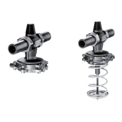
The flow regulator is designed to maintain the
flow rate in the pipeline at the set point ad-
justed at the restriction.
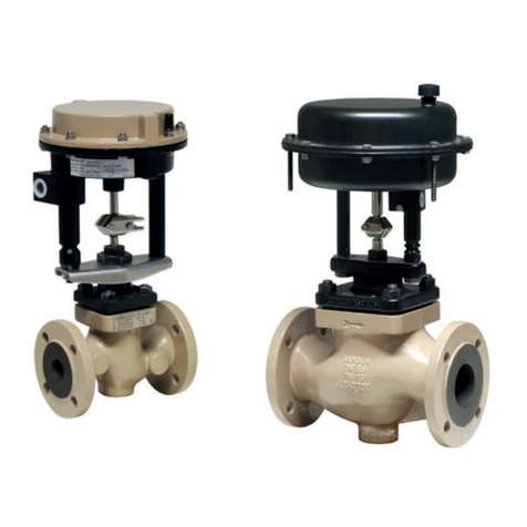
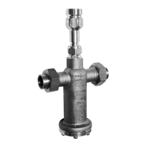
The regulator consists of a Type 2423 Valve
with a seat, plug and a restriction as well as a
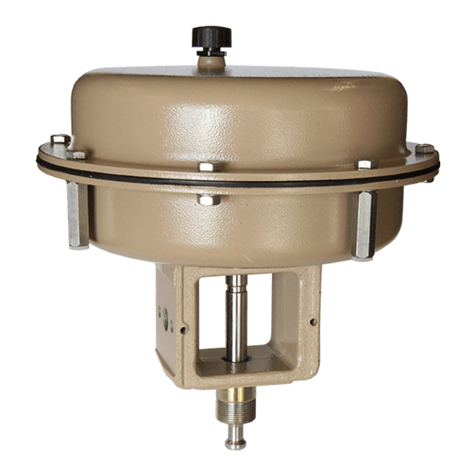
Type 2426 Closing Actuator with an operat-
ing diaphragm.
The valve and actuator are delivered as sepa-
rate units and must be connected with a cou-
pling nut on site.
Type 42-36 DoT
This version allows the additional control or
limitation of the temperature by attaching a
double adapter with a thermostat.
See the Mounting and Operating Instructions:
EB 3019 EN for the double adapter and
EB 2231 EN for Type 2231, Type 2232,
Type 2233, Type 2234 and Type 2235 Control
Thermostat.
The medium flows through the valve in the di-
rection indicated by the arrow. The flow rate
is determined by the free area between the re-
striction (1.1) and the valve plug (3).
The valve plug is unaffected by pressure
changes in the medium since the upstream
and downstream pressures are balanced by
the balancing bellows (5) or the balancing di-
aphragm (5.1) (DN 125 to 250/valve bal-
anced by a diaphragm).
The principle of operation of the regulators
with valves balanced by a bellows or dia-
phragm only differ concerning the pressure
balancing. The valves balanced by a dia-
phragm have a balancing diaphragm (5.1)
instead of a bellows (5). The downstream
pressure p2acts on the inside and the up-
stream pressure p1on the outside of the dia-
phragm or bellows. As a result, the forces act-
ing on the valve plug are balanced out.
The high pressure upstream of the restriction
(1.1) is transmitted through the control line
(18) to the lower diaphragm chamber. The
low pressure downstream of the restriction
(1.1) passes through the hollow plug stem (7)
and the diaphragm stem (6) into the top dia-
phragm chamber of the actuator. The differ-
ential pressure produced at the restriction is
converted into a positioning force at the oper-
ating diaphragm (12) and is used to move the
valve plug according to the force of the differ-
ential pressure springs (14). If the flow rate in-
creases, for example, the differential pressure
at the restriction also increases. The actuator
and plug stems move in the closing direction
and the flow rate is reduced until the flow rate
set point adjusted at the restriction (1.1) is
reached. If the flow rate decreases, the re-
verse takes place.
4EB 3015 EN
Design and principle of operation
