8
In order to maximize the quality of the sound you are capturing, you must pay
careful attention to the placement of your MTR231 and how it is positioned for
the instrument or vocalist. When the MTR231 is set to the cardioid polar pattern,
it exhibits a phenomenon known as “proximity effect” which is a resulting change
in the frequency response of a microphone based on the position of the micro-
phone capsule relative to the sound source. In order to get the best frequency
response, start by pointing the microphone directly on axis with the sound source.
You can change the sound characteristics that the microphone picks up by chang-
ing the position of the microphone. Rotating the microphone away (off-axis) from
the sound source will decrease the sensitivity to higher frequencies. Experimenta-
tion and experience is the best way to find out what sounds best for your record-
ings. Below are some tips for when setting up and using your MTR231 in typical
applications.
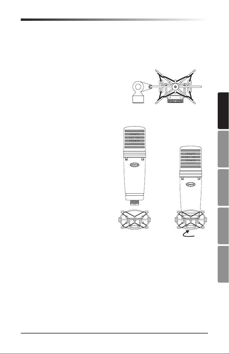
Vocals
With the microphone pattern switch
set to the cardioid position, place
the microphone directly in front of
the artist so that the microphone
grille is between 6 and 24 inches
away. The closer the vocalist moves
to the microphone, the more the
bass or low response increases.
As the vocalist moves away from
the microphone, the tone becomes
more natural as the low frequency
rolls off. To achieve the fullest sound, the vocalist should aim the microphone
center line towards their mouth. If some consonants such as ‘P’ and ‘S’ seem to
jump up in level, rotate the microphone a little bit away from the artist so that
sound arrives at the microphone slightly off-center. It is preferable to prevent
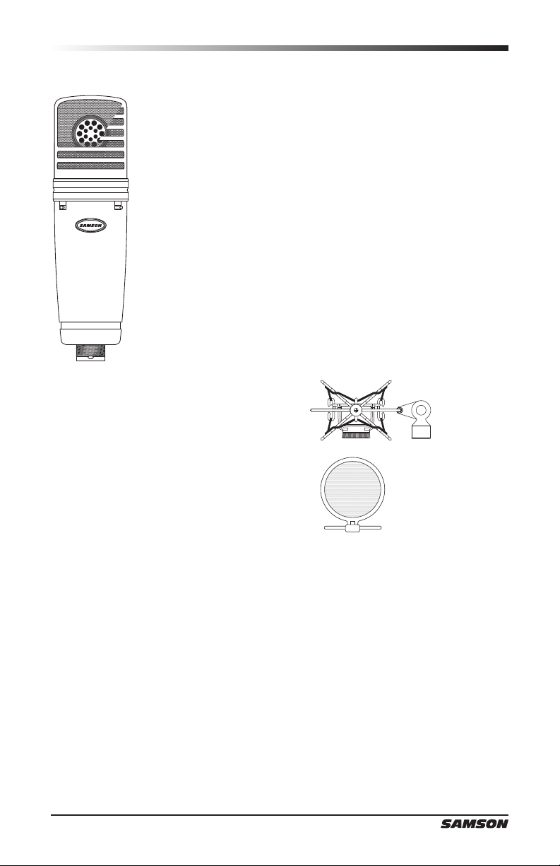
these peaks through the use of the MPF1 external pop filter. If recording a group
of singers, ensure that they position themselves around the front of the micro-
phone close to one another.
Acoustic Guitar
There are a variety of ways that the MTR231 can be used to mike an acoustic
guitar. Optimal microphone placement will depend on the type of instrument, and
what kind of sound you’re looking to capture. It may be necessary to experiment
with various positions to achieve full and balanced tone. When miking a stan-
dard steel string acoustic, it is suggested that you begin with the microphone at
a distance of 6–12 inches from the sound hole, positioned slightly off-axis, and
pointing towards the edge of the fingerboard. From this position, moving the mi-
crophone towards the sound hole will cause the mic to capture more low frequen-
cies. If, instead, you wish to capture more high-end, or to remove any unwanted
booming sound, move the microphone toward the fingerboard. Unlike a steel
string acoustic guitar, the sound of a nylon string acoustic guitar that is played by
Microphone Placement