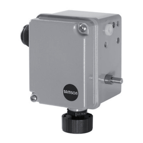
Samson 4740 Service manual

Mounting and
Operating Instructions
EB 8357 EN
Edition January 2015
Type4740 Electric Limit Switch

Denition of signal words
DANGER!
Hazardous situations which, if not
avoided, will result in death or seri-
ous injury
WARNING!
Hazardous situations which, if not
avoided, could result in death or seri-
ous injury
NOTICE
Property damage message or mal-
function
Note:
Additional information
Tip:
Recommended action
2 EB 8357 EN

Contents
EB 8357 EN 3
1 General safety instructions.............................................................................5
2 Markings on the device .................................................................................6
2.1 Nameplate ....................................................................................................6
2.2 Article code...................................................................................................6
3 Design and principle of operation ..................................................................7
3.1 Versions ........................................................................................................7
3.2 Technical data ...............................................................................................8
3.3 Dimensions in mm..........................................................................................9
4 Mounting and start-up.................................................................................10
4.1 MountingonType3353andType3354Valves..............................................10
4.1.1 Preparing the mounting kit............................................................................10
4.1.2 Mountingonthecontrolvalve .......................................................................12
4.2 MountingonType3379PneumaticActuator..................................................14
4.2.1 Preparing the mounting kit............................................................................14
4.2.2 Mounting on actuator...................................................................................16
4.3 Installation...................................................................................................18
4.3.1 Electrical connection.....................................................................................18
4.3.2 Pneumatic connection...................................................................................19
5 Start-up ......................................................................................................20
5.1 Adjustingthelimitcontacts ...........................................................................20
EB 8357 EN 5
General safety instructions
1 General safety instructions
For your own safety, follow these instructions concerning the mounting, start up, and opera-
tion of the limit switch:
ÎThedeviceistobemounted,starteduporoperatedonlybytrainedandexperienced
personnel familiar with the product.
According to these mounting and operating instructions, trained personnel refers to indi-
vidualswhoareabletojudgetheworktheyareassignedtoandrecognizepossibledan-
gersduetotheirspecializedtraining,theirknowledgeandexperienceaswellastheir
knowledgeoftheapplicablestandards.
ÎAnyhazardsthatcouldbecausedinthevalvebytheprocessmediumandtheoperating
pressureorbymovingpartsaretobepreventedbytakingappropriateprecautions.
ÎIfinadmissiblemotionsorforcesareproducedinthepneumaticactuatorasaresultof
thesupplypressurelevel,itmustberestrictedusingasuitablesupplypressurereducing
station.
To avoid damage to any equipment, the following also applies:
ÎDonotoperatethedevicewiththebackofthedevice/ventopeningfacingupwards.
ÎDonotsealtheventopeningwhenthedeviceisinstalledonsite.
Vent opening
ÎProper shipping and storage are assumed.
Note:
Devices with a CE marking fulll the requirements of the Directive 2004/108/EC.
The Declaration of Conformity is available on request.

6 EB 8357 EN
Markings on the device
2 Markings on the device
2.1 Nameplate
SAMSON 4740 Limit Switch
Model 4740-
Var-ID Serial no.
SAMSON AG D-60314 Frankfurt
12
3
45
Made in Germany
1Markingtoindicatewithout/withsolenoidvalve
2Markingtoindicateinductive/mechanicalproximityswitch
3 Article code
4CongurationID
5Serial no.
2.2 Article code
Limit switch Type4740- 0 0 0 x x x x 0 0 x x
Type
InductiveproximitysensorNCB2-V3-NO 1
MechanicalmicroswitchXGG12-88-S20 5
Switching element
With two switching elements (standard) 2
Solenoidvalve
Without 0
24VDC 1
Pneumatic connection
Without 0
Push-inL-connectorQS-G
1
/
8
-6 1
ISO228/1-G
1
/
8
2
Specialversion
Without 0 0

EB 8357 EN 7
Design and principle of operation
3 Design and principle of oper-
ation
TheType4740LimitSwitchcanbemounted
ontothefollowingdevices:
−Type3353AngleSeatValve(seeFig.1)
−Type3354GlobeValve
−Type 3379 Pneumatic Actuator
Theinductiveproximityswitchesormicros-
witchescausesignalstobesenttoacontrol
oralarmsystemwhenthetravelexceedsor
fallsbelowtheadjustedlimit.
Thelimitswitchcanoptionallybettedwith
a3/2-waysolenoidvalve.Whentheinte-
gratedsolenoidvalveisenergized,supply
air is applied to the actuator. When the so-
lenoidvalveisde-energized,theactuatoris
ventedandthecontrolvalvemovestoitsfail-
safe position.
The switching points of the limit contacts can
bechangedwithinthetravelrangeafterin-
stallation.Seesection5.1onpage20.
3.1 Versions
TwoversionsoftheType4740LimitSwitch
areavailable:
−Withinductiveproximityswitches
−With microswitches
Fig. 1: Type4740 Limit Switch with optional
solenoid valve on a Type3353 Angle
Seat Valve

8 EB 8357 EN
Markings on the device
3.2 Technical data
Electric limit switch Type4740
Travelrange 0to15mm
Ambienttemperaturerange –20to+65°C
Degree of protection IP65
Version with inductive proximity switches
Nominalvoltage 8.2VDCoverisolatingswitchamplieraccordingtoEN60947-
5-6
Version with microswitches
Switching capacity 250VAC,16(6)A
Option: 3/2-way solenoid valve
Nominalvoltage 24VDC
Power 1.5W
Flow rate 55ln/min(KV=0.035)
Maximumoperatingpressure 7bar
Pneumatic connection Push-inL-connectorQS-G
1
/
8
-6orISO228/1-G
1
/
8
Materials
Housing Polyamide
Cover Polycarbonate
Filter Polyethylene
Mounting kit Stainless steel
Weight
Limit switch (including solenoid
valve) Approx.550g
Mounting kit Approx.180g

EB 8357 EN 9
Markings on the device
3.3 Dimensions in mm
121
Ø94 22
M20 x 1.5

10 EB 8357 EN
Mounting and start-up
4 Mounting and start-up
4.1 Mounting on Type3353
and Type3354 Valves
Note:
The mounting unit (1400-9922) is re-
quired to mount the limit switch onto
the Type3353 Angle Seat Valve and
the Type3354 Globe Valve.
4.1.1 Preparing the mounting
kit
ÎSee Fig. 2
WARNING!
Risk of cut injury due to sharp
thread.
Do not touch the sharp thread of the
adapter.
Note:
The spacer (4) is only required to
mount the limit switch onto a fail-
close (FA/NC) valve.
Limit switch with inductive proximity switch-
es
ÎThreadtheguidedbushing(2)withthe
beveledpart(2.1)facingdownwardon-
to the stem of the adapter (3.1), while
holding the screw inside the adapter sta-
tionary.
Limit switch with microswitches
ÎThreadtheguidedbushing(2)withthe
straight rim (2.2) facing downward onto
the stem of the adapter (3.1), while hold-
ing the screw inside the adapter station-
ary.
Fail-open (FE/NO) version
ÎThe spacer is not required.
Fail-open (FA/NC) version
ÎInsertthespacer(4)intothesleeveofthe
adapter (3.2) as far as it will go.

EB 8357 EN 11
Mounting and start-up
Mounting kit for limit switch with
inductive proximity switches
Mounting kit for limit switch with
microswitches
2Threadedbushing
2.1 Beveledpart
2.2 Straight rim
3 Adapter
3.1 Stem
3.2 Sleeve
4 Spacer
2
3.1
3
3.2
4
2.1
2
2.2
2.1
2.2
2.2
2.1
Fig. 2: Mounting kit (1400-9922)

12 EB 8357 EN
Mounting and start-up
4.1.2 Mounting on the control
valve
ÎSee Fig. 3
WARNING!
Risk of personal injury due to pre-
loaded springs in the adapter.
Keep hold of the adapter when
screwing or unscrewing it and secure
it against sudden unintentional
release.
Fail-open (FE/NO) version
1. Use an open-end wrench (width across
ats32)orapairofplierstoremovethe
transparentcover(5.1)fromtheactuator
(5).
2. Use a socket wrench (width across
ats11)tounscrewthecap(5.2)from
the actuator stem.
3. Threadtheready-assembledadapter
(seesection4.1.1)fromthetopintothe
actuator(5).
ÎMake sure that the adapter does not
springbackasaresultofthespring
compression.
4. Carefully place the limit switch (1) on the
ready-assembledadapter.
ÎFortheversionwithmicroswitches,make
surethattheswitches(1.5)inthelimit
switch do not get damaged.
5. Lock the limit switch in the required posi-
tion using the retaining screw (1.4).
Fail-close (FA/NC)
1. Extendtheactuatorstem(applyairtothe
actuator).
2. Use an open-end wrench (width across
ats32)orapairofplierstoremovethe
transparentcover(5.1)fromtheactuator
(5).
3. Use a socket wrench (width across
ats11)tounscrewthecap(5.2)from
the actuator stem.
4. Retracttheactuatorstem(venttheactua-
tor).
5. Threadtheready-assembledadapter
(seesection4.1.1)fromthetopintothe
actuator(5).
ÎMake sure that the adapter does not
springbackasaresultofthespring
compression.
6. Carefully place the limit switch (1) on the
ready-assembledadapter.
ÎFortheversionwithmicroswitches,make
surethattheswitches(1.5)inthelimit
switch do not get damaged.
7. Lock the limit switch in the required posi-
tion using the retaining screw (1.4).

EB 8357 EN 13
Mounting and start-up
1
2
3
5
1.4
1 Limit switch
1.4 Retaining screw
1.5 Switch
2Threadedbushing
3 Adapter
5Actuator
5.1 Transparentcover
5.2 Cap
5.1
5.2
5
1.5
Fig. 3: Mounting the limit switch on the control valve

14 EB 8357 EN
Mounting and start-up
4.2 Mounting on Type3379
Pneumatic Actuator
Note:
The mounting kit (1402-1067) is re-
quired to mount the limit switch onto
the Type3379 Pneumatic Actuator.
4.2.1 Preparing the mounting
kit
ÎSee Fig. 4
WARNING!
Risk of cut injury due to sharp
thread.
Do not touch the sharp thread of the
adapter.
Limit switch with inductive proximity switch-
es
ÎThreadtheguidedbushing(2)withthe
beveledpart(2.1)facingdownwardon-
to the stem of the adapter (3.1), while
holding the screw inside the adapter sta-
tionary.
Limit switch with microswitches
ÎThreadtheguidedbushing(2)withthe
straight rim (2.2) facing downward onto
the stem of the adapter (3.1), while hold-
ing the screw inside the adapter station-
ary.

EB 8357 EN 15
Mounting and start-up
Mounting kit for limit switch with
inductive proximity switches
Mounting kit for limit switch with
microswitches
2Threadedbushing
2.1 Beveledpart
2.2 Straight rim
3 Adapter
3.1 Stem
2.1
2.2
2.2
2.1
2.1
2
2.2
2
3.1
3
Fig. 4: Mounting kit (1402-1067)

16 EB 8357 EN
Mounting and start-up
4.2.2 Mounting on actuator
ÎSeeFig.5
1. Use an open-end wrench (width across
ats32)orapairofplierstoremovethe
transparentcover(5.1)fromtheactuator
(5).
2. Pullthecap(5.2)offtheactuatorstem.
3. Threadtheready-assembledadapter
(seesection4.2.1)fromthetopintothe
actuator(5).
4. Carefully place the limit switch (1) on the
ready-assembledadapter.
ÎFortheversionwithmicroswitches,make
surethattheswitches(1.5)inthelimit
switch do not get damaged.
5. Lock the limit switch in the required posi-
tion using the retaining screw (1.4).

EB 8357 EN 17
Mounting and start-up
5.1
5.2
5
1.5
1 Limit switch
1.4 Retaining screw
1.5 Switch
2Threadedbushing
3 Adapter
5Actuator
5.1 Transparentcover
5.2 Cap
1
2
3
5
1.4
Fig. 5: Mounting the limit switch onto Type3379 Actuator

18 EB 8357 EN
Mounting and start-up
4.3 Installation
4.3.1 Electrical connection
DANGER!
Risk of electric shock!
For electrical installation, observe the
relevant electrotechnical regulations
and the accident prevention regula-
tions that apply in the country of use.
In Germany, these are the VDE regu-
lations and the accident prevention
regulations of the employers’ liability
insurance.
1. Unscrewthefourscrewsonhousingcov-
erandtakethecoverofftheactuator.
2. Routewiresthroughthecableglandto
the terminals as shown in Fig. 6.
3. Placeonthehousingcoverandfastenit.
+–
81 82
+–
51 52
+–
41 42
Proximityswitches Solenoidvalve
(option)
Version with inductive
proximity switches
+–
81 8252 5343 5141 42
Microswitches Solenoidvalve
(option)
Version with microswitches
Fig. 6: Electrical connection

EB 8357 EN 19
Mounting and start-up
4.3.2 Pneumatic connection
NOTICE
Risk of malfunction due to failure to
comply with required air quality.
−Only use supply air that is dry and
free of oil and dust.
−Read the maintenance instructions
for upstream pressure reducing sta-
tions.
−Blow through all air pipes and hos-
es thoroughly before connecting
them.
Twopneumaticconnectionsexistonthelimit
switchversionwithsolenoidvalve(seeFig.
7).
The following assignment apply to the con-
nections:
−Connection 1: Supply
−Connection 2: Output
Thescrewttingsaredesignedas:
−Push-inL-connectorQS-G
1
/
8
-6 or
−ISO228/1-G
1
/
8.
ÎSeearticlecodeonpage6
Note:
The pneumatic connections in the ver-
sion without solenoid valve are
sealed with stoppers.
Connection 1
Connection 2
Fig. 7: Pneumatic connection in this case with
push-in L-connector QS-G
1
/
8
-6

20 EB 8357 EN
Start-up
5 Start-up
5.1 Adjusting the limit contacts
The switching point of the limit contacts can
bechangedwithinthetravelrangeafterin-
stallation.
Toadjusttheswitchingpoint,proceedasfol-
lows:
1. Unscrewthefourscrewsonhousingcov-
erofthelimitswitchandtakethecover
off the actuator.
2. Loosen the two screws (1.1) of the limit
contact(1.3)tobeadjustedsothatthe
limitcontact(1.3)canmoveontherail
(1.4).
3. Adjusttheswitchingpointwiththescrew
(1.2):
ÎTurnthescrewclockwisetomovethelim-
it contact towards the top end position.
ÎTurnthescrewcounterclockwisetomove
thelimitcontacttowardsthebottomend
position.
4. Lock the limit contact (1.3) in position
with the screws (1.1).
5. Replacethehousingcoverofthelimit
switch and fasten down with the four
screws.
1.2
1.4
1.1
1.3
1.2
1.4
1.1
1.3
Version with inductive
proximity switches
Version with microswitches
1.1 Fastening screws
1.2 Adjustmentscrew
1.3 Limit contact
1.4 Rail
1.5 Switch
Fig. 8: Adjusting the limit contacts
Table of contents
Other Samson Switch manuals

Samson
Samson 3738-50 Service manual

Samson
Samson 4747 Service manual

Samson
Samson 3738-50 Instruction sheet

Samson
Samson 3738-20 Service manual

Samson
Samson EB 3773 Series Service manual

Samson
Samson 4747 Service manual

Samson
Samson 4746 Service manual

Samson
Samson 4746 Service manual

Samson
Samson 3776 Service manual

Samson
Samson 3768 Service manual
Popular Switch manuals by other brands

Moxa Technologies
Moxa Technologies EDS-516A Series Hardware installation guide

Vigitron
Vigitron MaxiiNet Vi3103 user manual

Asante
Asante IntraCore 35160 Series user manual

Freedom9
Freedom9 KVM-08P user manual

HPE
HPE FlexFabric 5700 Series Network management and monitoring configuration guide

NETGEAR
NETGEAR GS316 installation guide