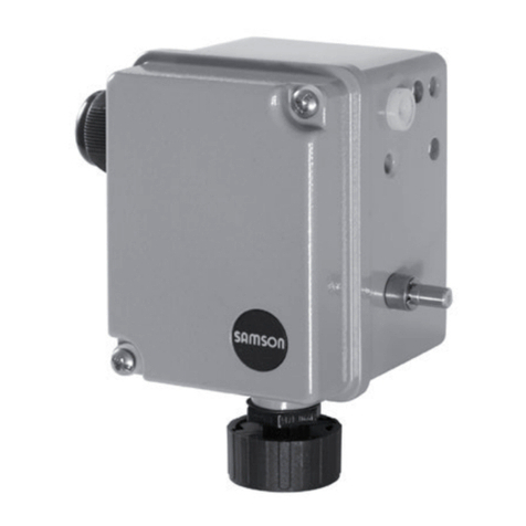
Samson 4746 Service manual

Mounting and
Operating Instructions
EB 8365 EN
Edition October 2013
Type 4746
Electric or Pneumatic Limit Switch

Denition of signal words
DANGER!
Hazardous situations which, if not
avoided, will result in death or seri-
ous injury
WARNING!
Hazardous situations which, if not
avoided, could result in death or se-
rious injury
NOTICE
Property damage message or mal-
function
Note:
Additional information
Tip:
Recommended action
2 EB 8365 EN
Note on these mounting and operating instructions
These mounting and operating instructions (EB) assist you in mounting and operating the de-
vice safely. The instructions are binding for handling SAMSON devices.
ÎFor the safe and proper use of these instructions, read them carefully and keep them for
later reference.
ÎIf you have any questions about these instructions, contact SAMSON's After-sales Service
department (aftersalesser[email protected]).
The mounting and operating instructions for the devices are included in
the scope of delivery. The latest documentation is available on our website
(www.samson.de) > Product documentation. You can enter the document
number or type number in the [Find:] eld to look for a document.
Referenced documentation
The documents for the devices used in combination with the limit switch apply in addition to
these mounting and operating instructions.

Contents
EB 8365 EN 3
1 General safety instructions.............................................................................5
2 Design and principle of operation ..................................................................6
2.1 Principle of operation.....................................................................................6
2.1.1 Type 4746-x Inductive Limit Switch..................................................................6
2.1.2 Type 4746-x3 Electric Limit Switch...................................................................6
2.1.3 Type 4746-04 Pneumatic Limit Switch..............................................................6
2.2 Article code and versions ...............................................................................8
2.3 Technical data .............................................................................................10
2.4 Accessories .................................................................................................12
2.5 Summary of explosion protection approvals...................................................12
3 Attachment to the valve ...............................................................................14
3.1 Attachment to valve with cast yoke ................................................................14
3.2 Attachment to valve with rod-type yoke..........................................................14
3.3 Attachment to Type3591 Valve.....................................................................16
3.4 Attachment to positioner...............................................................................18
4 Connections ................................................................................................19
4.1 Electrical connection.....................................................................................19
4.1.1 Switching amplier for Type 4746-x2............................................................21
4.2 Pneumatic connection for Type 4746-04........................................................21
5 Operation...................................................................................................22
5.1 Adjusting the switching point ........................................................................22
5.1.1 Type 4746-x2..............................................................................................22
5.1.2 Type 4746-x3 and Type4746-04 .................................................................23
6 Servicing explosion-protected devices ..........................................................24
7 Maintenance and calibration .......................................................................24
8 Dimensions .................................................................................................25
9 Certicates..................................................................................................26


EB 8365 EN 5
General safety instructions
1 General safety instructions
For your own safety, follow these instructions concerning the mounting, start up and opera-
tion of the device:
−The device is to be mounted, started up or operated only by trained and experienced
personnel familiar with the product.
According to these mounting and operating instructions, trained personnel refers to indi-
viduals who are able to judge the work they are assigned to and recognize possible dan-
gers due to their specialized training, their knowledge and experience as well as their
knowledge of the applicable standards.
−Explosion-protected versions of this device are to be operated only by personnel who has
undergone special training or instructions or who is authorized to work on explosion-pro-
tected devices in hazardous areas. Refer to section 6.
−Any hazards that could be caused in the valve by the process medium and the operating
pressure or by moving parts are to be prevented by means of appropriate measures.
If inadmissible motions or forces are produced in the pneumatic actuator as a result of
the supply pressure level, it must be restricted using a suitable supply pressure reducing
station.
To avoid damage to any equipment, the following also applies:
−Proper shipping and storage are assumed.
Note:
Positioners with a CE marking fulll the requirements of the Directives 2014/34/EU
and 2014/30/EU.
The Declarations of Conformity are included in the Appendix of these instructions.

6 EB 8365 EN
Design and principle of operation
2 Design and principle of oper-
ation
The limit switches are attached to pneumatic
control valves as well as to Type4765 and
Type4763 Positioners.
These limit switches have either inductive,
electric or pneumatic contacts. They issue a
signal when the valve travel exceeds or falls
below a limit, especially when a control
valve has reached its nal position. This sig-
nal is transmitted, e.g. to an alarm or indi-
cating system.
2.1 Principle of operation
The valve travel is transmitted either directly
to the pin (1.1) and lever (1) of the limit
switch by the plate (10) or by a coupling pin
when a positioner is attached. The linear
travel is converted into a rotary motion by
the shaft (2).
2.1.1 Type 4746-x Inductive
Limit Switch
In this version, the shaft (2) carries two
switch cases (3) with adjustable metal tags
(4.1) for non-contact activation of the inte-
grated proximity switches (5). For the opera-
tion of inductive limit switches (except for
Type4746-0281), appropriate switch ampli-
ers must be integrated into the output cir-
cuit.
The switching function and switching point
are continuously adjustable using the adjust-
ment screw (3.1).
2.1.2 Type 4746-x3 Electric
Limit Switch
In this version, the shaft (2) carries two
switch cases (3) with adjustable cam disks
(4.2). Each cam disk activates an electric
double-throw switch (7) over the roller (6.1),
which is attached to the switch lever (6). The
switching function and switching point are
continuously adjustable using the adjustment
screw (3.1).
2.1.3 Type 4746-04 Pneumatic
Limit Switch
In this version, the shaft (2) carries two
switch cases (3) with adjustable cam disks
(4.2). Each cam disk activates a nozzle/
apper system in the pneumatic switch (8).
Whenever the cam disk (4.2) activates the
switch lever (6) over the roller (6.1), the noz-
zle in the pneumatic switch (8) is opened
and the supply air from the microswitch (9)
is switched through to port A1or A2.
The nozzle is closed in the pneumatic switch
(8) and the supply air applied to the micro-
switch is cut off rst when the cam disk has
released the switch lever (6). As a result,
pressure is no longer applied to port A1or
A2.
The switching function and switching point
are continuously adjustable using the adjust-
ment screw (3.1).

EB 8365 EN 7
Design and principle of operation
3.1
3
5
L
10
4.1 1 1.12
L
3.1
3
1076.26.16
4.2 1 1.12
L
3.1
3
4.2 1 1.12
1086.26.16
A1A
2
99
8.2 8.1 8.1 8.2
pz
Inductive limit switch
Electric limit switch
Pneumatic limit switch with switching function
1 Lever for valve travel
1.1 Pin
2 Shaft
3 Switch case
3.1 Adjustment screw
4.1 Metal tag
4.2 Cam disk
5 Proximity switch
6 Switch lever
6.1 Roller
6.2 Spring
7 Electric switch
8 Pneumatic switch
8.1 Nozzle (in switch)
8.2 Flapper (in switch)
9 Pneumatic microswitch
10 Plate attached either to
actuator stem or plug stem
Fig. 1: Functional drawings

8 EB 8365 EN
Design and principle of operation
2.2 Article code and versions
Limit switch (device index .07 and higher) Type 4746- x x x x x x x 0 x x x x
Explosion protection
Without 0
Ex II 2G Ex ia IIC T6 acc. to ATEX 1
CSA/FM intrinsically safe/non incendive 3
Ex II 3G Ex nA II T6 acc. to ATEX 8
Type
Inductive 2 1/2
Electric 3 2
Pneumatic 0 4 2
Contacts
Proximity switch SC3,5-N0-YE 1) 2 0 0 1 0
Proximity switch SJ3,5-SN 2 1 0 1 0
Proximity switch SJ3,5-S1N 2 1 1 1 0
SAIA, electric microswitch XGK 3 320210
SAIA, electric microswitch XGK3-81 321210
Pneumatic microswitch 0 4 4 0 2 0
Proximity switch SB3,5-E2 0281210
Switching elements
With one switching element 1
With two switching elements 2
Electrical connection
Without 0 4 4 0 0
Plastic cable gland M20 x 1.5, black 1 0
Pneumatic connections
Without 0
ISO 221/1-G
1
/
8
0 4 4 0 0 1
1
/
8
-27 NPT 0 4 4 0 0 2
Special versions
Without 000
NEPSI approval Ex ia, Type 4746-12 inductive 1 2 2 0 0 9
NEPSI approval Ex nL, Type 4746-82 inductive 8 2 2 0 1 0
GOST approval Ex ia, Type 4746-1... 1 2/3 0 1 3
KOSHA approval Ex ia 1 2/3 0 1 5
1) Type4746-3200 only with FM approval

EB 8365 EN 9
Design and principle of operation
Compatibility with paint
Without 0
Free from substances that impair paint adhesion 1
Limit switch (device index .06 or lower) Type 4746- x x x x
Type
Inductive, no explosion protection 1
Inductive, Ex ib IIC T6 2
Electric 3
Pneumatic 4
Electrical connection/lever
Without
0
Cable gland, lever I (device index .04 or higher without lever)
1
Cable gland, lever for positioner attachment
2
½” USA cable gland, lever I
3
½” USA cable gland, lever for positioner attachment
4
Contacts
SJ3,5-N
0
SJ3,5-SN
1
SAIA electric microswitch XGK 3
2
Pneumatic microswitch with ISO 228/1-G
1
/
8
connecting thread
3
Pneumatic microswitch with
1
/
8
-27 NPT connecting thread
4
SJ3,5-N (white dot of paint), max. hysteresis with 100 mm lever = 0.6 mm
5
Microswitch (gold contacts)
6
SJ3,5-E2 with LED (three-wire switch) without explosion protection, NO contact
1 8
SB3,5-E2 (three-wire switch) without explosion protection, NO contact
19
Switching elements
With one switching element 1
With two switching elements 2
Note:
When replacing devices with index .00 to .03, a mounting unit with lever must also
be ordered. See section 2.4.

10 EB 8365 EN
Design and principle of operation
2.3 Technical data
Inductive Limit Switch Type 4746-x2 Type 4746-0281
Control circuit Switching amplier according to EN 60947-5-6 Three-wire switch
Operating voltage 10 to 30 V
Proximity switch SC3,5-N0-YE 2) SJ3,5-SN SJ3,5-S1N SB3,5-E2
Permissible ambient temperature 1) –20 to 70 °C –20 to 100 °C –20 to 100 °C –20 to 70 °C
with metal cable gland –40 to 70 °C –50 to 100 °C –40 to 100 °C –25 to 70 °C
Electrical connections One M20x1.5 cable gland for 5.5 to 13 mm clamping range
Screw terminals for 0.2 to 2.5 mm² wire cross-section
Degree of protection IP 65
Weight Approx. 0.7 kg
Type 4746-x3 Electric Limit Switch · Specications apply to silver and gold-plated contacts
Switching element Electric limit switch: changeover/SPDT (single-pole/double-throw type)
Permissible load AC voltage: 220 V, 6.9 A
DC voltage: 220 V, 0.25 A · 20 V, 6.9 A
Permissible ambient temperature 1) –20 to 85 °C
with metal cable gland –40 to 85 °C
Electrical connections One M20x1.5 cable gland for 5.5 to 13 mm clamping range
Screw terminals for 0.2 to 2.5 mm² wire cross-section
Degree of protection IP 65
Weight Approx. 0.7 kg
Type 4746-04 Pneumatic Limit Switch
Switching element
Pneumatic limit switch with downstream pneumatic microswitch
Supply air 1.4 bar (20 psi), can be briey overloaded up to 4 bar (60 psi)
Air consumption 0.04 mn3/h
Output 0 or 1.4 bar (20 psi)
Air capacity One switch closed: 0.7 mn3/h · Two switches closed: 1.0 mn3/h
Permissible ambient temperature –20 to 60 °C
Degree of protection IP 54
Weight Approx. 0.75 kg

EB 8365 EN 11
Design and principle of operation
Materials
Housing and cover Powder-coated aluminum
Lever and shaft 1.4571
Cable gland M20x1.5, black polyamide
Travel range
Attachment according to
IEC60534-6 (NAMUR) Lever I: 7.5 to 60 mm · Lever II: 60 to 180 mm
Attachment to Type 4763 and
Type 4765 Positioner Travel same as positioner
Compliance ·
1) Observe the limits specied in the EC-type examination certicate.
2) Models manufactured until 2006 with SJ3,5-N proximity switch.
Type 4746-1 with type of protection Ex ia (ATEX)
Maximum values for connection to certied intrinsically safe circuits
Limit Switch Type 4746-12 Type 4746-13
Limit contacts Inductive Electric
Ui16 V 16 V 45 V
Ii52 mA 25 mA –
Pi169 mW 64 mW 2 W
Ci- effective inner capacitance 60 nF 50 nF Negligibly small
Li- effective internal inductance 160 µH 250 µH
Temperature classes Ambient temperature range according to EC-type examination certicate
(technical data specied in above table additionally apply)
T4 –45 to 89 °C –45 to 100 °C –45 to 80 °C
T5 –45 to 60 °C –45 to 81 °C –45 to 70 °C
T6 –45 to 45 °C –45 to 66 °C –45 to 60 °C

12 EB 8365 EN
Design and principle of operation
2.4 Accessories
Accessories for attachment according to IEC 60534-6
Valve Cast yoke (NAMUR rib)
(see section 3.1) Rod-type yoke (18 to 32 mm rod diameter)
(see section 3.2)
Travel Up to 60 mm Up to 180 mm Up to 60 mm Up to 180 mm
Mounting kit order no. 1400-6713
(lever I) 1400-6714
(lever II) 1400-6713 (lever I)
plus 1400-5342 1400-6714 (lever II)
plus 1400-5342
Accessories for attachment to Type 4763 and Type 4765 Positioner (see section 3.4)
Mounting kit order no. 1400-6710
Accessories for attachment to Type 3351 Valve (see section 3.2)
Nominal size DN 15 to 50 DN 65 to 100
Mounting kit order no. 1400-6585 1400-6586
Accessories for attachment to Type 3591 Valve with lever II (see section 3.3)
Mounting kit order no. 1402-0662
Vent plugs
Technical data G¼ connection, –50 to +80°C, material 1.4404,
degree of protection IP65
Order no. 1991-2110
2.5 Summary of explosion protection approvals
Type Certicate Type of protection
4746 STCC Number No. 977 0Ex ia IIC T6X
2Ex s II T6X
Valid until 2017-10-01
4746-1
Number RU C.DE.08.00744
1Ex ia IIC T6/T5/T4 Gb XDate 2015-01-27
Valid until 2020-01-26
Number 3-KB4BO-0038
Ex ia IIC T6/T5/T4Date 2013-01-31
Valid until 2016-01-31
4746-12
Number GYJ15.1221
Ex ia IIC T4~T6 GbDate 2015-06-16
Valid until 2020-06-15

EB 8365 EN 13
Design and principle of operation
Type Certicate Type of protection
4746-1x
Number PTB 98 ATEX 2114
II 2G Ex ia IIC T6 Gb
Date 2003-03-07
EC type examination
certicate
4746-3
Number 1607226 Ex ia IIC T6; Class I, Zone 0;
Class I,II, Div.1, Groups A,B,C,D,E,F,G;
Class I,II, Div.2, Groups A,B,C,D,E,F,G;
Date 2005-09-16
4746-32
4746-33
Number 3020228 Class I, Zone 0 AEx ia IIC
Class I,II,III; Div.1, Groups A,B,C,D,E,F,G
Class I, Div.2, Groups A,B,C,D;
Class II, Div,2 Groups F,G; Class III;
Date 2005-02-28
4746-8
Number RU C.DE.08.00744 2Ex nA IIC T6/T5/T4 Gc X
2Ex ic IIC T6/T5/T4 Gc X
Date 2015-01-27
Valid until 2020-01-26
4746-82
Number GYJ15.1222X Ex ic IIC T4~T6 Gc
Ex nA IIC T4~T6 Gc
Date 2015-06-16
Valid until 2020-06-15
Number PTB 02 ATEX 2012 X
II 3G Ex nA II T6
Date 2002-04-05
Statement of
conformity
4746-83
Number PTB 02 ATEX 2012 X
II 3G Ex nA II T6
Date 2002-04-05
Statement of
conformity

14 EB 8365 EN
Attachment to the valve
3 Attachment to the valve
The accessories listed in section 2.4 are re-
quired for attachment.
ÎThe lever (I or II) must be installed before
the limit switch is attached to the control
valve. To do so, slide the lever clamping
plate (1.1) over the lever (1) and slip
them onto the shaft (2). Tighten the fas-
tening screw (1.2).
3.1 Attachment to valve with
cast yoke
1. Attach the plate (10) to the valve's stem
connector using two screws (10.1).
2. Attach the pin (11) to the plate (10) us-
ing two nuts (11.1).
3. Unscrew the cover of the limit switch. At-
tach the limit switch to the valve yoke us-
ing the mounting screw (12), washer
(13) and O-ring (14).
Make sure that the pin (11) is inserted
through the wire strap (1.3) of the lever
(1).
3.2 Attachment to valve with
rod-type yoke
1. Attach the plate (10) to the valve's stem
connector using two screws (10.1).
2. Attach the pin (11) to the plate (10) us-
ing two nuts (11.1).
3. Fasten the support (15) and the rod
clamping plate (16) loosely to the rod.
In the valve travel mid-position, move the
support until the center of the plate (10)
and the support (15) are aligned.
4. Fasten the rod clamping plate.
5. Attach the limit switch to the support us-
ing the mounting screw (12), washer
(13) and O-ring (14). Make sure that the
pin (11) is inserted through the wire
strap (1.3) of the lever (1).
ÎAfter attaching the limit switch, make
sure that the vent plug of the housing
cover faces downward when the valve is
installed

EB 8365 EN 15
Attachment to the valve
12 13 14
1.12 1.2 1 1.3 11 11.1 1010.1
12
13 15 16
1.12 1.2 1 1.3 11 11.1 1010.1
14
Attachment to valve with cast yoke (NAMUR rib)
Attachment to valve with rod-type yoke
1 Lever
1.1 Clamping plate
1.2 Screw
1.3 Wire strap
2 Shaft
10 Plate
10.1 Screws
11 Pin
11.1 Nuts
12 Screw
13 Washer
14 O-ring
15 Support
16 Rod clamping plate
Fig. 2: Attachment to the valve

16 EB 8365 EN
Attachment to the valve
3.3 Attachment to Type3591
Valve
ÎUse the supplied washers for all screw
connections.
1. Fasten the round brackets (1) using the
clamps (3) and nuts (2) lightly onto the
valve yoke.
2. Screw tight the bar (4) using the screws
(5) onto the clamps (3).
3. Fasten the limit switch (6) onto the bar
(4) as described in step 3 of section 3.1.
Use the thread (7) in the bar.
4. Fasten the mounting bracket (9) using the
screws (10) to the anti-rotation xture (8)
of the valve.
5. Screw the follower clamp (11) to the
mounting bracket (9) using the nut and
bolt (12).
6. Insert the pin (13) into the oblong hole of
the follower clamp (11). Make sure that
the pin is inserted through the wire strap
of the follower clamp.
7. Thread the nut (14) onto the pin (13).
Place the clamp (16) over the lever (15)
of the limit switch (6).
8. Use the nut (17) to fasten the lever (15)
onto the lever extension (18).
9. Fasten the other end of the lever exten-
sion (18) to the follower clamp (11).
10.Perform alignment.
The following applies concerning attach-
ment:
ÎPerform the alignment in such a way that
the lever (15), lever extension (18) and
oblong hole of the follower clamp (11)
are in line with each other.
ÎAfter attaching the limit switch, make
sure that the vent plug of the housing
cover faces downward when the valve is
installed.

EB 8365 EN 17
Attachment to the valve
7
16
14
13
8
9
10
11
1
7
12
1 Round clamp
2 Nut
3 Clamp
4 Bar
5 Screws
6 Limit switch
7 Thread
8 Anti-rotation xture
9 Mounting bracket
10 Screws
11 Follower clamp
12 Nut and bolt
13 Pin
14 Nut
15 Lever II
16 Clamp (for lever)
17 Nut
18 Lever extension
Fig. 3: Attachment to Type3591 Valve
8
15
11
18
10
9
4
5
3
1
2
6

18 EB 8365 EN
Attachment to the valve
3.4 Attachment to positioner
For attachment of the limit switch to the
Type4763 or 4765 Positioner according to
Fig. 4, a short lever (1) and an intermediate
piece (31) are required as accessories (order
no. 1400-6710).
1. Insert one O-ring (30) into both the left
and the right side of the intermediate
piece (31).
2. Push the two llister head screws (33)
through the limit switch and intermediate
piece, and insert them into the positioner.
3. Insert the nuts (32) into the positioner
housing and screw tight the two llister
head screws (33).
Make sure that the short lever (1) slides
over the pin (16) of the positioner.
4. Replace the vent plug (17) in the posi-
tioner housing with the screw plug in-
cluded in the accessories (order no.
1400-6710).
In exchange, insert the vent plug into the
housing of the limit switch. This ensures
that the degree of protection of the limit
switch corresponds to that of the posi-
tioner.
ÎTo achieve degree of protection IP 65, a
check valve (order no. 1790-7408)
needs to be installed in the housing of
the limit switch.
17
AB
30
31
161
31
32
33
NOTICE
Attach the housing cover to the limit switch
ensuring that the vent plug (17) faces
downward after the valve is installed.
Lever with spring
Sectional view A – B
Fig. 4: Attachment with intermediate piece, e.g. to Type 4765 or Type 4763 Positioner

EB 8365 EN 19
Connections
4 Connections
4.1 Electrical connection
DANGER!
For electrical installation, observe the
relevant electrotechnical regulations
and the accident prevention regula-
tions that apply in the country of use.
In Germany, these are the VDE regu-
lations and the accident prevention
regulations of the employers’ liability
insurance.
The following regulations apply to
installation in hazardous areas:
EN60079-14:2008 (VDE 0165,
Part1) Explosive Atmospheres– Elec-
trical Installations Design, Selection
and Erection.
NOTICE
Adhere to the terminal assignment!
Switching the assignment of the elec-
trical terminals may cause the explo-
sion protection to become ineffec-
tive. Do not loosen enameled screws
in or on the housing. The maximum
permissible values specied in the
EC-type examination certicates ap-
ply when interconnecting intrinsically
safe electrical equipment.
(Ui and U0, Iiand I0, Piand P0, Ci
and C0as well as Liand L0)
Note on the selection of cables and
wires:
Observe clause12 of EN60079-14
(VDE0165, Part1) for installation of
the intrinsically safe circuits.
Clause12.2.2.7 applies when run-
ning multi-core cables and wires with
more than one intrinsically safe cir-
cuit.
The radial thickness of the insulation
of a conductor for common insulating
materials (e.g. polyethylene) must not
be smaller than 0.2mm. The diame-
ter of an individual wire in a ne-
stranded conductor must not be
smaller than 0.1mm. Protect the con-
ductor ends against splicing, e.g. by
using wire-end ferrules.
When two separate cables are used
for connection, an additional cable
gland can be installed. Seal cable en-
tries left unused with plugs. Fit equip-
ment used in ambient temperatures be-
low –20°C with metal cable entries.

20 EB 8365 EN
Connections
Note concerning equipment for use
in zone 2:
In equipment operated according to
type of protection ExnA II (non-
sparking equipment) according to
EN60079-15:2003, circuits may be
connected, interrupted or switched
while energized only during installa-
tion, maintenance or repair.
Equipment connected to energy-lim-
ited circuits with type of protection
ExnL (energy-limited equipment) ac-
cording to EN60079-15:2003 may
be switched under normal operating
conditions. The maximum permissi-
ble values specied in the statement
of conformity or its addenda apply
when interconnecting the equipment
with energy-limited circuits in type of
protection ExnLIIC.
Other manuals for 4746
1
Table of contents
Other Samson Switch manuals

Samson
Samson 4740 Service manual

Samson
Samson 4746 Service manual

Samson
Samson 3738-50 Instruction sheet

Samson
Samson 3738-20 Service manual

Samson
Samson 3776 Service manual

Samson
Samson 3768 Service manual

Samson
Samson 4747 Service manual

Samson
Samson 4747 Service manual

Samson
Samson 3738-50 Service manual

Samson
Samson EB 3773 Series Service manual