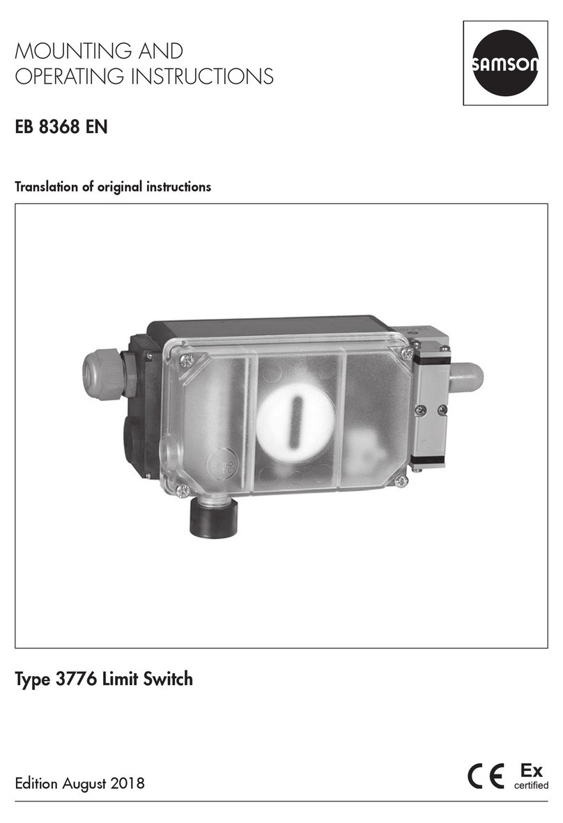
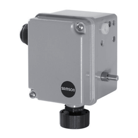
Samson 3768 Service manual

Mounting and
Operating Instructions
EB 8356 EN
Edition February 2013
Type3768 Inductive Limit Switch

Denition of signal words
DANGER!
Hazardous situations which, if not
avoided, will result in death or seri-
ous injury
WARNING!
Hazardous situations which, if not
avoided, could result in death or seri-
ous injury
NOTICE
Property damage message or mal-
function
Note:
Additional information
Tip:
Recommended action
2 EB 8356 EN
Note on these mounting and operating instructions
These mounting and operating instructions (EB) assist you in mounting and operating the de-
vice safely. The instructions are binding for handling SAMSON devices.
ÎFor the safe and proper use of these instructions, read them carefully and keep them for
later reference.
ÎIf you have any additional questions not related to the contents of these instructions, con-
The mounting and operating instructions for all supplied devices are
included in the delivery. The latest versions of the documents are available
on our website at www.samson.de > Product documentation. You can
enter the document number or type number in the [Find:] eld to look for
a document.
Referenced documentation
The documents for the devices used in combination with the limit switch apply in addition to
these mounting and operating instructions.

Contents
EB 8356 EN 3
1 General safety instructions.............................................................................5
2 Design and principle of operation ..................................................................6
2.1 Technical data ...............................................................................................7
2.2 Versions and article code................................................................................8
2.3 Summary of explosion protection approvals.....................................................9
3 Attachment to the valve ...............................................................................10
3.1 Direct attachment.........................................................................................10
3.1.1 Attachment of version with solenoid valve ......................................................10
3.2 Attachment according to IEC60534-6...........................................................12
3.2.1 Mounting sequence......................................................................................12
3.2.2 Initial adjustment of travel.............................................................................14
3.3 Attachment to rotary actuators ......................................................................14
3.3.1 Mounting the lever with feeler roll..................................................................14
3.3.2 Mounting the intermediate piece ...................................................................14
3.3.3 Aligning the cam disk...................................................................................16
3.3.4 Reversing amplier for double-acting actuators ..............................................18
4 Electrical connections...................................................................................24
4.1 Pneumatic connections for version with solenoid valve.....................................27
5 Operation – Adjusting the limit contacts .......................................................28
6 Servicing explosion-protected devices ..........................................................30
7 Maintenance and calibration .......................................................................30
8 Dimensions in mm.......................................................................................31


EB 8356 EN 5
General safety instructions
1 General safety instructions
For your own safety, follow these instructions concerning the mounting, start-up, and opera-
tion of the device:
−The device is to be mounted, started up or operated only by trained and experienced
personnel familiar with the product. According to these mounting and operating instruc-
tions, trained personnel refers to individuals who are able to judge the work they are as-
signed to and recognize possible dangers due to their specialized training, their knowl-
edge and experience as well as their knowledge of the applicable standards.
−Explosion-protected versions of this device are to be operated only by personnel who has
undergone special training or instructions or who is authorized to work on explosion-pro-
tected devices in hazardous areas. See section6.
−Any hazards that could be caused in the valve by the process medium and the operating
pressure or by moving parts are to be prevented by taking appropriate precautions. If in-
admissible motions or forces are produced in the pneumatic actuator as a result of the
supply pressure level, it must be restricted using a suitable supply pressure reducing sta-
tion.
To avoid damage to any equipment, the following also applies:
−Proper shipping and storage are assumed.
Note:
Devices with a CE marking fulll the requirements of the Directive 2014/34/EU and
the Directive 2014/30/EU. The declaration of conformity is included at the end of
these instructions.

6 EB 8356 EN
Design and principle of operation
2 Design and principle of oper-
ation
The Type3768 Limit Switch is designed for
attachment to pneumatic control valves. It is
tted with inductive contact limits that issue a
limit signal whenever the valve travel ex-
ceeds or falls below a certain preset limit, es-
pecially when the valve has reached one of
its end positions. The limit signal is transmit-
ted to alarm or indicating equipment.
The limit switch can also available be tted
with a solenoid valve to move the valve to its
fail-safe position.
The limit switch is designed either for direct
attachment to SAMSON Type3277 Actua-
tors or for attachment to actuators according
to IEC60534-6 (NAMUR) using an adapter
housing.
The valve travel is transmitted by the pin
(1.1) to the lever (1) and converted into a ro-
tary motion. The shaft (2) transfers this rota-
ry motion to two adjustable metal tags (4)
which operate the associated proximity
switches (5).
The operation of the inductive limit switches
requires switching ampliers to be connected
in the output circuit (see section4).
Version with solenoid valve
When tted with a solenoid valve, the con-
trol valve can be moved to the fail-safe posi-
tion, regardless of the control signal issued
by the control equipment. If a control signal
corresponding to the binary signal '0' (OFF)
is applied to the input, the signal pressure pst
is shut off and the actuator is vented. The ac-
tuator springs move the valve to its fail-safe
position.
When a control signal corresponding to the
binary signal '1' (ON) is applied to the in-
put, the signal pressure pst is applied to the
actuator, allowing the valve to move accord-
ing to the input signal issued by the control
equipment.
46
5
3211.1
7
supply
u[V]
pst
1Lever
1.1 Coupling pin
2 Shaft
3 Spring
4Metal tag
5Proximity switch
6Adjustment screw
7 Pressure regulator
Fig. 1: Functional diagram

EB 8356 EN 7
Design and principle of operation
2.1 Technical data
Travel range Direct attachment to Type3277 Actuator: 7.5 to 30mm
Attachment according to IEC60534 (NAMUR):
7.5 to 120mm
Inductive proximity switches 2x SJ2-SN
Control circuit Specications corresponding to connected switching
amplier
Hysteresis at rated travel ≤1%
Permissible ambient temperature –20 to +80°C with plastic cable gland
–40 to +80°C with metal cable gland
Special version down to –45°C
The limits in the type examination certicate additionally
apply to explosion-protected versions.
Solenoid valve
Supply air Supply air: 1.4 to 6bar (20 to 90psi)
Input Binary DC voltage signal
Nominal signal 6V DC 12VDC 24VDC
Signal '0' (no response) 1) ≤ 1.2V ≤ 2.4V ≤ 4.7V
Signal '1' (response) 2) ≥ 5.4V ≥ 9.6V ≥ 18.0V
Coil resistance Ri at 20°C 2909Ω 5832Ω 11714Ω
KV coefcient 0.14m³/h
Air consumption 'OFF' ≤60ln/h · 'ON' ≤10ln/h
Closing time with Type3277 Actuator 240cm² 350cm² 700cm²
For rated travel with
bench range
0.2 to 1bar ≤1s ≤1.5s ≤4s
0.4 to 2bar ≤2s ≤2.5s ≤8s
0.6 to 3bar ≤1s ≤1.5s ≤5s
Degree protection
without/with solenoid
valve
Without IP65
With IP65 (IP65 and NEMA 4X, lter check valve,
see Table4 on page22)
Compliance ·
Materials
Housing Die-cast aluminum, chromated and plastic coated
External parts Stainless steel 1.4571 and 1.4104
1) DC voltage signal at –20°C
2) DC voltage signal at +80°C

8 EB 8356 EN
Design and principle of operation
2.2 Versions and article code
Limit switch Type3768- x 2x0 0 xxxx0x x 0
Explosion protection
Without 0 2/7
II 2G Ex ia IIC T6 acc. to ATEX 1
CSA/FM intrinsically safe/non incendive 3
II 3G Ex nA II T6 acc. to ATEX 82/7
Solenoid valve
Without 0
6V DC 2
12V DC 3
24VDC 4
Pneumatic connections
Without 0 0
¼-18NPT 1
ISO221/1-G¼ 2
Electrical connection
Plastic cable gland M20x1.5, blue 1 0
Plastic cable gland M20x1.5, black 2 0
Cable gland M20x1.5, nickel-plated brass 7 2
Body version
Aluminum 0
CrNiMo steel 2
Temperature range
Standard 0
–45 to 80°C 2
Special versions
On request x x x x

EB 8356 EN 9
Design and principle of operation
2.3 Summary of explosion protection approvals
Type Certication Type of protection
3768-1
Number GYJ15.1218X
Ex ia IIC T4...T6 GbDate 2015-06-16
Valid until 2020-06-15
No. PTB 02 ATEX 2077
II 2G Ex ia IIC T6
Date 2002-07-19
EC type examination
certicate
3768-3
Number 1607265 Ex ia IIC T6; Class I Zone 0;
Class I, II, Div. 1, Groups A, B, C, D, E, F,
G;
Class I, II, Div. 2, Groups A, B, C, D, E, F,
G;
Date 2005-06-19
No. 3020228 Class I, Zone 0 AEx ia IIC
Class I, II, III, Div. 1, Groups A, B, C, D, E,
F, G
Class I, Div. 2, Groups A, B, C, D;
Class II, Div. 2 Groups F, G; Class III
Date 2005-02-28
3768-8
Number GYJ15.1219X
Ex ic IIC T4...T6 Gc
Ex nA IIC T4...T6 Gc
Date 2015-06-16
Valid until 2020-06-15
Number PTB 03 ATEX 2182 X
II 3G Ex nA II T6
Date 2003-09-30
Statement of
conformity
3768-9
Number RU C-DE08.B.00199 1Ex ia IIC T6/T5/T4 Gb X
Ex tb IIIC T80°C Db X
2Ex nA IIC T6/T5/T4 Gc X
2Exic IIC T6/T5/T4 Gc X
Ex tc IIIC T80°C Dc X
Date 2014-02-14
Valid until 2019-02-13

10 EB 8356 EN
Attachment to the valve
3 Attachment to the valve
The limit switch can be mounted either di-
rectly to SAMSON Type3277 Actuator or to
valves with cast yokes or rod-type yokes ac-
cording to IEC60534-6 (NAMUR).
Combined with an intermediate piece, the
limit switch can also be mounted on rotary
actuators.
The standard limit switch is delivered without
accessories. Any additionally required ac-
cessories are listed together with their order
numbers in the tables on page20 on-
wards.
The limit switch may be mounted on the
right-hand or left-hand side of the valve.
Any subsequent changes to the mounting
position cause the switching function of the
limit switch to change as well. See section5.
3.1 Direct attachment
1. Fasten the clamp (1.2) to the actuator
stem, making sure that the fastening
screw rests in the groove of the actuator
stem.
2. Fasten the associated lever D1 or D2 to
the lever of the limit switch.
3. Secure the intermediate plate (15) with
the gasket facing towards the yoke.
4. Position and fasten the limit switch onto
the intermediate plate, making sure that
the lever D1 or D2 slides in line over the
pin(1.1) of the clamp (1.2).
5. Mount cover (18).
6. Mount the vent plug suitable for the cor-
responding degree of protection on the
cover (18).
3.1.1 Attachment of version
with solenoid valve
To establish the signal pressure connection to
the actuator, use a connection block or swi-
tchover plate listed in the tables in
page20 onwards. An M3 screw plug is
located on the back of this device version.
Actuators with 240 to 700cm² effective
areas
1. Make sure that the tip of the gasket(16)
projecting from the side of the connec-
tion block (Fig. 2, middle) is positioned
to match the actuator symbol for the ac-
tuator's fail-safe action "actuator stem
extends" or "actuator stem retracts".
If this is not the case, unscrew the three
fastening screws and lift off the cover.
Turn the gasket (16) by 180° and re-in-
sert it.
The old connection block version requires
the switch plate (13) to be turned to align
the actuator symbol with the arrow mark-
ing.
2. Place the connection block with the asso-
ciated gaskets against the limit switch
and the yoke. Fasten it using the screw.
For actuators with fail-safe action "actua-
tor stem retracts", additionally mount the
external signal pressure pipe.
SUPPLY
1.2
18
D2
D1
15
15
Type3277
Connection block
only for version with
solenoid valve
Switchover plate
only for version with solenoid valve
Type3277-5 with 120cm²
View onto the signal pressure connection
< Left attachment Right attachment >
Actuator stem
< extends retracts >
Signal pressure connection
< internal over pipe connection >
With switch plate (old)
Switch plate (13)
Marking
Marking
Actuator stem
retracts
Symbol for
actuator stem
retracts
Symbol for
actuator stem
retracts
Signal pressure
input for left
attachment
Signal pressure
input for right
attachment
Tip of gasket
(16)
extends
extends
Clamp
extends
Cover
Side view of
connection block
with gaskets (new)
Fig. 2: Direct attachment · Mounting of the clamp and signal pressure connection for version with
solenoid valve

EB 8356 EN 11
Attachment to the valve
3 Attachment to the valve
The limit switch can be mounted either di-
rectly to SAMSON Type3277 Actuator or to
valves with cast yokes or rod-type yokes ac-
cording to IEC60534-6 (NAMUR).
Combined with an intermediate piece, the
limit switch can also be mounted on rotary
actuators.
The standard limit switch is delivered without
accessories. Any additionally required ac-
cessories are listed together with their order
numbers in the tables on page20 on-
wards.
The limit switch may be mounted on the
right-hand or left-hand side of the valve.
Any subsequent changes to the mounting
position cause the switching function of the
limit switch to change as well. See section5.
3.1 Direct attachment
1. Fasten the clamp (1.2) to the actuator
stem, making sure that the fastening
screw rests in the groove of the actuator
stem.
2. Fasten the associated lever D1 or D2 to
the lever of the limit switch.
3. Secure the intermediate plate (15) with
the gasket facing towards the yoke.
4. Position and fasten the limit switch onto
the intermediate plate, making sure that
the lever D1 or D2 slides in line over the
pin(1.1) of the clamp (1.2).
5. Mount cover (18).
SUPPLY
1.2
18
D2
D1
15
15
Type3277
Connection block
only for version with
solenoid valve
Switchover plate
only for version with solenoid valve
Type3277-5 with 120cm²
View onto the signal pressure connection
< Left attachment Right attachment >
Actuator stem
< extends retracts >
Signal pressure connection
< internal over pipe connection >
With switch plate (old)
Switch plate (13)
Marking
Marking
Actuator stem
retracts
Symbol for
actuator stem
retracts
Symbol for
actuator stem
retracts
Signal pressure
input for left
attachment
Signal pressure
input for right
attachment
Tip of gasket
(16)
extends
extends
Clamp
extends
Cover
Side view of
connection block
with gaskets (new)
Fig. 2: Direct attachment · Mounting of the clamp and signal pressure connection for version with
solenoid valve

12 EB 8356 EN
Attachment to the valve
Actuator with 120cm² diaphragm area
The signal pressure is transmitted to the dia-
phragm chamber over the switchover plate.
1. Remove the M3 screw plug at the back
of the limit switch and use the blanking
plug from the accessories to seal the sig-
nal pressure output (Output 38) at the
side.
2. Mount the limit switch so that the hole in
the intermediate plate (15) covers the
seal in the hole of the yoke.
3. Align the switchover plate with the corre-
sponding actuator symbol. Fasten it to
the yoke.
3.2 Attachment according to
IEC60534-6
The mounting parts listed in Table5 are re-
quired for limit switch attachment. The rated
travel of the valve determines which lever is
to be used.
An adapter housing is used for NAMUR at-
tachment. The valve travel is transmitted by
the lever (18) and the shaft (25) to the brack-
et (28) of the adapter housing and then
passed on to the pin (27a) on the lever of
the limit switch.
To ensure that the pin (27a) is properly locat-
ed in the bracket (28), x the spring includ-
ed in the accessories at the back of the posi-
tioner housing as illustrated in Fig. 3.
The limit switch can be mounted either on the
left or right side of the valve.
Spring Screw plug
Fig. 3: Installing the spring on the back
3.2.1 Mounting sequence
ÎSelect the required mounting parts from
the tables on page20 onwards.
Valve with cast yoke:
1. Screw the plate (20) to the stem connec-
tor of the actuator and plug stems using
the countersunk screws.
Use the additional bracket (32) for 2100
and 2800cm² actuators.
2. Remove the rubber stopper from the
adapter housing and fasten the adapter
housing either on the left or right of the
NAMUR rib using the hexagon head
screw.
Valve with rod-type yoke:
1. Screw the plate (20) to the follower
clamp of the plug stem.
2. Screw the studs (29) into the adapter
housing.
3. Place the adapter housing with the plate
(30) onto either the left or right valve rod
and screw tight using the nuts (31). Make
sure that the adapter housing is at the
18 Lever N1, N2
19 Pin
20 Plate
21 Clip
22 Clamping plate
23 Screw
24 Pointer
25 Shaft
26 Lever of positioner
27a Coupling pin
27b Lock nut
28 Bracket
29 Studs
30 Plate
31 Nuts
32 Mounting bracket
2
1,5
1
2826
AB
24 25 22
32
31
20 19
19 21 2023 18
27b
27a
29
30
Mounting position
Attachment to
NAMUR rib
Attachment to rods
Fig. 4: Attachment according to NAMUR (shown for left attachment)

EB 8356 EN 13
Attachment to the valve
Spring Screw plug
Fig. 3: Installing the spring on the back
3.2.1 Mounting sequence
ÎSelect the required mounting parts from
the tables on page20 onwards.
Valve with cast yoke:
1. Screw the plate (20) to the stem connec-
tor of the actuator and plug stems using
the countersunk screws.
Use the additional bracket (32) for 2100
and 2800cm² actuators.
2. Remove the rubber stopper from the
adapter housing and fasten the adapter
housing either on the left or right of the
NAMUR rib using the hexagon head
screw.
Valve with rod-type yoke:
1. Screw the plate (20) to the follower
clamp of the plug stem.
2. Screw the studs (29) into the adapter
housing.
3. Place the adapter housing with the plate
(30) onto either the left or right valve rod
and screw tight using the nuts (31). Make
sure that the adapter housing is at the
18 Lever N1, N2
19 Pin
20 Plate
21 Clip
22 Clamping plate
23 Screw
24 Pointer
25 Shaft
26 Lever of positioner
27a Coupling pin
27b Lock nut
28 Bracket
29 Studs
30 Plate
31 Nuts
32 Mounting bracket
2
1,5
1
2826
AB
24 25 22
32
31
20 19
19 21 2023 18
27b
27a
29
30
Mounting position
Attachment to
NAMUR rib
Attachment to rods
Fig. 4: Attachment according to NAMUR (shown for left attachment)

14 EB 8356 EN
Attachment to the valve
correct height to mount the lever (18) so
that it is in a horizontal position when
the valve is at mid-travel.
4. Screw the pin (19) into the middle row of
holes on the plate (20) and lock it into
position over the correct lever marking (1
to 2) as indicated in Table6.
5. Clamp the clip (21) onto the lever (18).
The clip must be clamped onto the lever
(18) with the open side facing down-
ward for attachment of the version with
solenoid valve and with front air connec-
tion.
6. Attach the lever (18) including clamping
plate (22) to the shaft (25), making sure
that the clip clasps the pin (19).
3.2.2 Initial adjustment of
travel
1. Move the valve to 50% travel.
2. Move the shaft (25) in the adapter hous-
ing so that the black pointer (24) match-
es the cast marking on the adapter hous-
ing.
3. Fasten the clamping plate (22) in this po-
sition using the screw (23).
4. Screw the pin (27a) into the limit switch
lever on the side where the press nut is
located. Lock it in position with the hex
nut (27b) on the other side, observing
the mounting position Aor Baccording
to Table6 and Fig. 4.
5. Place the limit switch on the adapter
housing, taking into account the mount-
ing direction. Fasten it, making sure that
the pin (27a) rests against the bracket
(28).
Make sure the pin does not slip out of the
bracket once installed.
3.3 Attachment to rotary actu-
ators
The limit switch can also be mounted on ro-
tary actuators (attachment according to VDI/
VDE3845, September 2010, xing level 2)
using the mounting parts listed in Table7 on
page23. The rotary motion of the rotary
actuator is transferred to the metal tags over
the cam disk on the actuator shaft and the
feeler roll on the limit switch lever.
Note:
The range spring (1890-4418) from
the mounting kit (1400-8815) is not
required for this attachment.
3.3.1 Mounting the lever with
feeler roll
1. Place the lever with feeler roll (35) on the
side of the lever (37) opposite to where
the press nuts are located and secure it
using the supplied screws (38) and
washers.
3.3.2 Mounting the interme-
diate piece
SAMSON Type3278 Actuator
1. Fasten the adapter (36) to the free shaft
end of the rotary actuator.
40 Cam disk
41 Actuator shaft
42 Washer
43 Mounting bracket
44 Coupling
45 Gasket
33 Limit switch
34 Intermediate piece
35 Lever with feeler roll
36 Adapter
37 Transmission lever
38 Screws
39 Dial plate
33
3835
39
39
40
34
36
40
34
44
45
42
43
37
Attachment to
SAMSON Type3278
Attachment
according to
VDI/VDE3845
Vent plug or lter check
valve
Fig. 5: Attachment to rotary actuators

EB 8356 EN 15
Attachment to the valve
the pin (27a) rests against the bracket
(28).
Make sure the pin does not slip out of the
bracket once installed.
3.3 Attachment to rotary actu-
ators
The limit switch can also be mounted on ro-
tary actuators (attachment according to VDI/
VDE3845, September 2010, xing level 2)
using the mounting parts listed in Table7 on
page23. The rotary motion of the rotary
actuator is transferred to the metal tags over
the cam disk on the actuator shaft and the
feeler roll on the limit switch lever.
Note:
The range spring (1890-4418) from
the mounting kit (1400-8815) is not
required for this attachment.
3.3.1 Mounting the lever with
feeler roll
1. Place the lever with feeler roll (35) on the
side of the lever (37) opposite to where
the press nuts are located and secure it
using the supplied screws (38) and
washers.
3.3.2 Mounting the interme-
diate piece
SAMSON Type3278 Actuator
1. Fasten the adapter (36) to the free shaft
end of the rotary actuator.
40 Cam disk
41 Actuator shaft
42 Washer
43 Mounting bracket
44 Coupling
45 Gasket
33 Limit switch
34 Intermediate piece
35 Lever with feeler roll
36 Adapter
37 Transmission lever
38 Screws
39 Dial plate
33
38
35
39
39
40
34
36
40
34
44
45
42
43
37
Attachment to
SAMSON Type3278
Attachment
according to
VDI/VDE3845
Vent plug or lter check
valve
Fig. 5: Attachment to rotary actuators

16 EB 8356 EN
Attachment to the valve
2. Fasten the intermediate piece (34) to the
actuator housing using two screws.
For the version with solenoid valve, align
the intermediate piece so that the air
connections of the limit switch point to-
ward the diaphragm case side.
3. Align the cam disk and scale as de-
scribed in section3 and fasten.
4. Screw the vent plug (or lter check valve
from the accessories) into the intermedi-
ate piece.
Actuators according to VDI/VDE3845
1. Place the assembled intermediate piece
(34, 44, 45, and 42) onto the mounting
bracket included in the scope of actuator
delivery and fasten (attachment accord-
ing to VDI/VDE3845, September 2010,
xing level 2).
2. Align the cam disk (40) and scale as de-
scribed in section3 and fasten.
3. Screw the vent plug (or lter check valve
from the accessories) into the intermedi-
ate piece.
3.3.3 Aligning the cam disk
ÎRefer to Fig. 6
The following applies on aligning the cam
disk:
ÎThe cam disk alignment depends on the
valve's direction of rotation, i.e. whether
it opens clockwise or counterclockwise.
ÎThe cam disk must be set when the valve
is closed.
ÎAlign the starting point (hole) of the cam
so that the fulcrum of the cam disk and
0° position on the scale as well as the ar-
row on the window are in line with each
other.
ÎWhen aligning the cam disk, clip the
double-sided scale disk on the cam disk,
while making sure that the value on the
scale matches the valve's direction of ro-
tation.
Securing the aligned cam disk
To prevent the cam disk from turning, pro-
ceed as follows:
ÎDrill a hole into the adapter(36) or cou-
pling (44) to allow a 2mm dowel pin to
be inserted.
ÎSelect one of the four holes located
around the center hole of the cam disk to
secure the cam disk in position.
90˚
60˚
30˚
0˚ 0˚
90˚
60˚
30˚
Feeler roll
Starting point Starting point
Insert clip and press
the aps outwards
Valve opens in counterclockwise direction Valve closes in clockwise direction
Fig. 6: Aligning the cam disk

EB 8356 EN 17
Attachment to the valve
3.3.3 Aligning the cam disk
ÎRefer to Fig. 6
The following applies on aligning the cam
disk:
ÎThe cam disk alignment depends on the
valve's direction of rotation, i.e. whether
it opens clockwise or counterclockwise.
ÎThe cam disk must be set when the valve
is closed.
ÎAlign the starting point (hole) of the cam
so that the fulcrum of the cam disk and
0° position on the scale as well as the ar-
row on the window are in line with each
other.
ÎWhen aligning the cam disk, clip the
double-sided scale disk on the cam disk,
while making sure that the value on the
scale matches the valve's direction of ro-
tation.
Securing the aligned cam disk
To prevent the cam disk from turning, pro-
ceed as follows:
ÎDrill a hole into the adapter(36) or cou-
pling (44) to allow a 2mm dowel pin to
be inserted.
ÎSelect one of the four holes located
around the center hole of the cam disk to
secure the cam disk in position.
90˚
60˚
30˚
0˚ 0˚
90˚
60˚
30˚
Feeler roll
Starting point Starting point
Insert clip and press
the aps outwards
Valve opens in counterclockwise direction Valve closes in clockwise direction
Fig. 6: Aligning the cam disk

18 EB 8356 EN
Attachment to the valve
3.3.4 Reversing amplier for
double-acting actuators
Limit switches tted with a solenoid valve
which are intended for use with double-act-
ing actuators must be equipped with a re-
versing amplier.
SAMSON Type3710 Reversing Amplier
We recommend using a Type3710 Revers-
ing Amplier. Refer to the mounting and op-
erating instructions uEB8392 for more in-
formation on how to mount and connect the
Type3710.
Reversing amplier (1079-1118 or 1079-
1119)
If a different reversing amplier (item no.
1079-1118 or 1079-1119) is used, follow
the mounting instructions described below:
ÎRefer to Fig. 7
1. Remove the sealing plug (1.5). The rub-
ber seal (1.4) must remain installed.
2. Screw the special nuts (1.3) from the ac-
cessories of the reversing amplier into
the threaded connections of the limit
switch.
3. Insert the gasket (1.2) into the recess of
the reversing amplier and slide both the
hollowed special screws (1.1) into the
connecting boreholes A1 and Z.
4. Place the reversing amplier onto the
limit switch and screw tight using the two
special screws (1.1).
The following applies to all reversing am-
pliers:
The signal pressure of the positioner is sup-
plied at the output 1 of the reversing ampli-
er. An opposing pressure, which equals the
required supply pressure (Z) when added to
the pressure at output 1, is applied at output
2.
The following relationship applies:
Output 1 + Output 2 = Supply pressure (Z).
ÎConnect output 1 to the signal pressure
connection on the actuator that causes
the valve to open when the pressure ris-
es. Connect output 2 to the signal pres-
sure connection on the actuator that
causes the valve to close when the pres-
sure rises.
Note:
How the outputs are marked depends
on the reversing amplier used:
−Type3710: Output 1/2 = Y1/Y2
−1079-1118 and 1079-1119:
Output 1/2 = A1/A2
1Reversing amplier
1.1 Special screws
1.2 Gasket
1.3 Special nuts
1.4 Rubber seal
1.5 Stopper
1.3 1.2 1.1 1
Output 38 Supply 9
A1
1.5 1.6
Z
A2
1.4
A1A2
Output 38 Supply 9
1.3 1.21.1
1.6
Z
A1
From the limit switch
To the actuator Vent plug or lter check
valve
Fig. 7: Mounting a reversing amplier (item number 1079-1118 or 1079-1119)

EB 8356 EN 19
Attachment to the valve
3.3.4 Reversing amplier for
double-acting actuators
Limit switches tted with a solenoid valve
which are intended for use with double-act-
ing actuators must be equipped with a re-
versing amplier.
SAMSON Type3710 Reversing Amplier
We recommend using a Type3710 Revers-
ing Amplier. Refer to the mounting and op-
erating instructions uEB8392 for more in-
formation on how to mount and connect the
Type3710.
Reversing amplier (1079-1118 or 1079-
1119)
If a different reversing amplier (item no.
1079-1118 or 1079-1119) is used, follow
the mounting instructions described below:
ÎRefer to Fig. 7
1. Remove the sealing plug (1.5). The rub-
ber seal (1.4) must remain installed.
2. Screw the special nuts (1.3) from the ac-
cessories of the reversing amplier into
the threaded connections of the limit
switch.
3. Insert the gasket (1.2) into the recess of
the reversing amplier and slide both the
hollowed special screws (1.1) into the
connecting boreholes A1 and Z.
4. Place the reversing amplier onto the
limit switch and screw tight using the two
special screws (1.1).
1Reversing amplier
1.1 Special screws
1.2 Gasket
1.3 Special nuts
1.4 Rubber seal
1.5 Stopper
1.3 1.2 1.1 1
Output 38 Supply 9
A1
1.5 1.6
Z
A2
1.4
A
1A2
Output 38 Supply 9
1.3 1.21.1
1.6
Z
A1
From the limit switch
To the actuator Vent plug or lter check
valve
Fig. 7: Mounting a reversing amplier (item number 1079-1118 or 1079-1119)

20 EB 8356 EN
Attachment to the valve
Table1: Mounting kits for direct attachment (see Fig. 2 on page11)
Actuator size Lever with associated clamp and intermediate plate Order no.
120cm² D1 lever with stopper for output (38) Standard version 1400-7116
Version compatible with paint 1402-0944
175, 240, 350cm² D1 lever (33mm long with 17mm clamp) Standard version 1400-6370
Version compatible with paint 1402-0942
355, 700, 750cm² D2 lever (44mm long with 13mm clamp) Standard version 1400-6371
Version compatible with paint 1402-0943
Table2: Mounting kits for direct attachment for version with solenoid valve
Switchover/connecting plate: Actuator Order no.
Switchover plate for 120cm² actuator Type 3277-5xxxxxx.00 Actuator (old) 1400-6819
New switchover plate Actuator with index .01 and higher (new) 1400-6822
Connecting plate for additional attachment of, e.g.
a solenoid valve 3277-5xxxxxxxx.00 (old) G
1
/
8
1400-6820
1
/
8
NPT 1400-6821
New connecting plate Actuator with index .01 and higher (new) 1400-6823
Note:
Only new switchover and connecting plates can be used with new actuators (Index 01).
Old and new plates are not interchangeable.
Required connection block for 175, 240, 350, 355, 700, and 750cm² actuator
(including gaskets and fastening screw)
G¼ 1400-8811
¼NPT 1400-8812
Table of contents
Other Samson Switch manuals

Samson
Samson 4740 Service manual

Samson
Samson 4747 Service manual

Samson
Samson 4746 Service manual

Samson
Samson 3776 Service manual

Samson
Samson 4746 Service manual

Samson
Samson 3738-50 Instruction sheet

Samson
Samson 3738-20 Service manual

Samson
Samson 4747 Service manual

Samson
Samson EB 3773 Series Service manual

Samson
Samson 3738-50 Service manual