Samson 3738-50 Instruction sheet
Translation of original instructions
KH 8390-5 EN
Firmware version 1.01
Type 3738-50 Electronic Limit Switch
Communication: FOUNDATION™ eldbus
Edition December 2013
The mounting and operating instructions for the devices are included in
the scope of delivery. The latest documentation is available on our website
at www.samson.de > Service & Support > Downloads > Documentation.
Denition of signal words
Hazardous situations which, if not avoided,
will result in death or serious injury
Hazardous situations which, if not avoided,
could result in death or serious injury
Property damage message or malfunction
Additional information
Recommended action
DANGER
!
WARNING
!
NOTICE
!
Note
Tip
2 KH 8390-5 EN
Refer to the Mounting and Operating Instructions EB 8390-5 for details on mounting, start-
up and local operation of the electronic limit switch.
Note

Contents
KH 8390-5 EN 3
1 Introduction ..................................................................................................5
2 Principle of operation ....................................................................................6
2.1 Versions ........................................................................................................6
2.1.1 Forced venting ...............................................................................................6
2.2 Operating/congurationmode .......................................................................6
3 CongurationusingTROVIS-VIEWsoftware....................................................8
3.1 CongurationusingtheNI-BUS™Congurator................................................8
3.2 Communication .............................................................................................8
4 FOUNDATION™ eldbusblockmodel........................................................9
5 Writeprotection ..........................................................................................10
6 Endpositioncalibrationinthedevice ...........................................................10
7 Resettingthedevice.....................................................................................10
8 Statusclassicationandcondensedstate......................................................11
9 Blockmodel ................................................................................................14
9.1 ResourceBlock(RES) ....................................................................................14
9.2 FunctionBlocks ............................................................................................14
9.2.1 DiscreteInputFunctionBlock(DI1FBtoDI5FB) ..............................................14
9.2.2 DiscreteOutputFunctionBlock(DO1FBtoDO5FB) .......................................16
9.2.3 AnalogInputFunctionBlock(AIFB)...............................................................17
9.3 TransducerBlocks.........................................................................................17
9.3.1 LimitSwitchTransducerBlock(LSTRD) ...........................................................18
10 Parameters .................................................................................................18

4 KH 8390-5 EN

KH 8390-5 EN 5
Introduction
1 Introduction
This section is based upon:
−Fieldbus FOUNDATION™Specication“FunctionBlockApplicationProcessPart1–3“Re-
vision1.7(FF-890toFF-892)
−Fieldbus FOUNDATION™Specication“PositionerTransducerBlock“Revision3.0(FF-
906)
Type 3738-50 Electronic Limit Switch
TheType3738-50ElectronicLimitSwitchallowson/offvalvestobeactuatedbyanintegrat-
ed or external solenoid valve as well as their discrete end positions to be read out by a
FOUNDATION™eldbusnetworkaccordingtoIEC61158-2.
Specialfeatures:
−LinkMasterCapability
−PowersuppliedbyFOUNDATION™eldbus
(solenoidvalvewithlowenergyconsumptionof6VDC)
−Simplediscreteactuationofon/offvalvesovera
FOUNDATION™
eldbusnetwork
−Easytoattachtocommonlyavailablelinearactuators(NAMURattachment)aswellas
rotaryactuatorsaccordingtoVDI/VDE3845
−Non-contactsensingoftherotationanglebyamagnetoresistivesensorsystem
−Simpleone-knob,menu-drivenoperation
−Automaticstart-up
−LCD easy to read in any mounting position due to selectable reading direction
−Integrateddiagnosticswithpartialstroketesting(PST)
−Classiedstatusalarmsacc.toNAMURRecommendationNE107
−Parameterscanbechangedonline
−Permanentstorageofallparametersinnon-volatileEEPROM(protectionagainstpowerfail-
ure)
−Version with integrated solenoid valve or for external solenoid valve

6 KH 8390-5 EN
Principle of operation
2 Principle of operation
The electronic limit switch is designed for attachment to pneumatic actuators. The current
valvepositionismeasuredwithoutcontactusingamagnet(onascrew)positionedcentrically
ontheactuatorshaft.Thescrewwithmagnetdoesnotneedtobeadjusted.TheAMR(aniso-
tropicmagnetoresistive)sensorlocatedinthedevicetogetherwiththemeasuringelectronics
(1)candetectthedirectionalchangeoftheappliedmagneticeldand,asaresult,sensethe
movement of the actuator.
Thepneumaticactuatorisoperatedbyasolenoidvalve(6,8)whichconvertsthesignalis-
sued by the control system into a binary pressure signal.
2.1 Versions
Versionwithintegratedsolenoidvalve(Type3738-50-xxx4x00x1x00x0)
The solenoid valve is integrated into the housing of the electronic limit switch. The electronic
limit switch and the solenoid valve are powered by the connected FOUNDATION™eldbus
two-wirecableaccordingtoIEC61158-2.
Versionforexternalsolenoidvalve(Type3738-50-xxx0x00x1x00x0)
The electronic limit switch and the external solenoid valve are powered by the connected
FOUNDATION™eldbustwo-wirecableaccordingtoIEC61158-2.
2.1.1 Forcedventing
Theelectroniclimitswitchcanoptionallybettedwithaforcedventing function. This func-
tionisactivatedwhenthesolenoidvalveisde-energizedafterthepowersupplyisinterrupt-
ed,causingtheactuatortomovethecontrolvalvetoitsfail-safeposition.
2.2 Operating/congurationmode
Theelectroniclimitswitchhastwomodes:theoperatingmode(RUN)andtheconguration
mode(SET).SwitchoverbetweenthetwomodesisperformedintheOperatingmodeparam-
eterupage 40.
−RUN:Operatingmode:congurationforstart-upandpartialstroketesting(PST)not pos-
sible
−SET: Congurationmode:(nooperation),congurationforstart-upandpartialstroke
testing(PST)
KH 8390-5 EN 7
Principle of operation
T
SSP
interface
11 10
3FOUNDATION™
fieldbus
IEC 61158-2
2
5
8*
1
912
4
Signal for forced venting*
6
7
Electronic
limit switch
A
ctuator
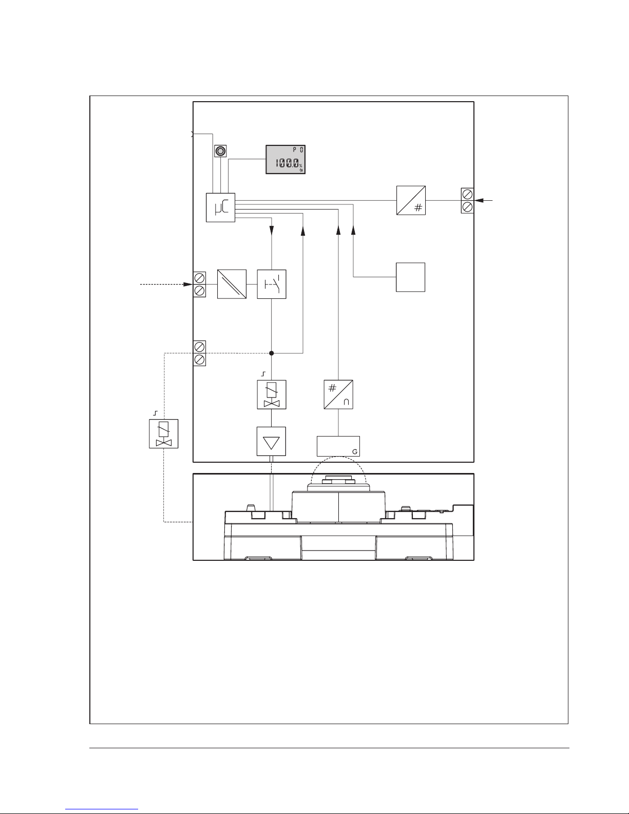
1 AMRsensorwithelectronics
2 A/D converter
3 Microcontroller
4 Interfacemodule(IEC61158-2)
5 Actuationofforcedventing
6 Solenoidvalve
(Type3738-50-xxx4x00x1x00x0)
7 Air capacity booster
(Type3738-50-xxx4x00x1x00x0)
8* External solenoid valve
(Type3738-50-xxx0x00x1x00x0)
9 Electrical isolation
10 Display
11 Rotary pushbutton
12 Temperature sensor
* Optional
Fig.1: Functional diagram of Type 3738-50 Electronic Limit Switch

8 KH 8390-5 EN
CongurationusingTROVIS-VIEWsoftware
3 CongurationusingTROVIS-VIEWsoftware
TheelectroniclimitswitchcanbeconguredusingtheTROVIS-VIEWCongurationandOp-
eratorInterfacesoftware.
The electronic limit switch is equipped with an additional digital serial interface to connect
theRS-232orUSBportofthecomputertotheelectroniclimitswitchoveranadaptercable.
TheTROVIS-VIEWsoftwareenablestheusertoeasilysetparametersintheelectroniclimit
switch and view process parameters online.
3.1 CongurationusingtheNI-BUS™Congurator
TheNI-FBUS™ConguratorfromNationalInstrumentscanalsobeusedtocongurethe
electronic limit switch. An FF interface card is required for connection to FOUNDATION™eld-
bus.
TheintegratedfunctionblockscanbelinkedusingtheNI-FBUS™Congurator.
3.2 Communication
The electronic limit switch is completely controlled over the digital signal transmission imple-
mented according to FOUNDATION™eldbusspecication.
Dataaretransmittedoverthebususingdigital,bit-synchronousManchestercodingata
baudrateof31.25kbit/sovertwisted-pairwiresaccordingtoIEC61158-2.
If complex functions are started in the electronic limit switch, which require a long calculation
time or lead to a large quantity of data being saved in the volatile memory of the electronic
limit switch, the alert ‘busy’ is issued over FOUNDATION™eldbus. This alert is not an error
message and can be simply conrmed.
Note

KH 8390-5 EN 9
FOUNDATION™eldbusblockmodel
4 FOUNDATION™ eldbusblockmodel
FOUNDATION™eldbus assigns all the functions and data of a device to different types of
blocks.Eachtypeofblockhasadifferentrangeoftaskstofulllintheblockmodel.Thefol-
lowingtypesofblocksareimplementedintheSAMSONType3738-50ElectronicLimit
Switch:
ResourceBlock(RES)
TheResourceBlockcontainsallthespeciccharacteristicsassociatedwithadeviceonthe
eldbus,forexample,devicename,manufacturernumberandserialnumber.Adevicecan
onlyhaveoneResourceBlock.
FunctionBlocks(FB)
FunctionblocksareresponsibleforthecontrolbehaviorofaFOUNDATION™eldbusdevice.
A FOUNDATION™eldbusapplicationcanbeconguredbyconnectingtheinputsandout-
putsoffunctionblocks.ThefollowingfunctionblocksareimplementedintheType3738-50:
5xDiscreteInputFunctionBlocks(DIFB);executiontime20ms
5xDiscreteOutputFunctionBlocks(DOFB);executiontime30ms
1xAnalogInputFunctionBlock(AIFB)
analogpositionfeedback;executiontime20ms
TransducerBlocks(TRD)
EachAIorAOFunctionBlockhasaTransducerBlockwhichcontainsalldataandde-
vice-specicparameterstolinkthedevicetotheprocessvalue(sensorornalcontrolele-
ment).
ThefollowingTransducerBlocks(correspondingtotheFunctionBlocks)areimplemented:
1x LimitSwitchTransducerBlock(LSTRD)
5x DiscreteInputTransducerBlocks(DITRD)
5x DiscreteOutputTransducerBlocks(DOTRD)
1x AnalogInputTransducerBlock(AITRD)

10 KH 8390-5 EN
Writeprotection
5 Writeprotection
The Local operation parameter upage28allowsthelocaloperation(accessusing
TROVIS-VIEWandon-siteoperation)oftheelectroniclimitswitchtobelocked.Anactive
lockingisindicatedby on the display.
Operation over the FOUNDATION™ eldbus network can be locked by the local operation
(Code P18). When this locking function is active, device data can only be read over the
FOUNDATION™ eldbus network, but data in the device cannot be overwritten.
6 Endpositioncalibrationinthedevice
Whenthezeropointorendpositionsareincorrect,itmaybenecessarytorecalibratethem.
Alwaysperformanendpositioncalibrationforthefail-safepositionandfortheoperating
position. The end position calibration can be started by the START_ABORT_CMD parameter
oftheLSTranducerBlock.StatusinformationcanbereadintheStatusofendpositioncali-
bration parameter upage 38.
The end position calibration is automatically canceled if an error occurs. The error can be
read in the ACTUAL_DEVICE_ERROR(70)parameteroftheLSTranducerBlock.
7 Resettingthedevice
Resettingstart-updata
Resetthestart-updataintheP21parameter(localoperation).
Resettingidenticationdataandtheblockconguration
Resettheidenticationdatafortheelectroniclimitswitch,valveandactuatorbyselecting‘3’
in the RESET_CMD(63)parameteroftheLSTranducerBlock.Additionally,thesettingsofthe
functionblocksareresettotheirdefaultsettings.Thestart-updataandloggingsremain
saved.
Note
Other manuals for 3738-50
1
Table of contents
Other Samson Switch manuals

Samson
Samson EB 3773 Series Service manual

Samson
Samson 4746 Service manual

Samson
Samson 4747 Service manual

Samson
Samson 4740 Service manual

Samson
Samson 3738-20 Service manual

Samson
Samson 4747 Service manual

Samson
Samson 3768 Service manual

Samson
Samson 3776 Service manual

Samson
Samson 3738-50 Service manual

Samson
Samson 4746 Service manual


