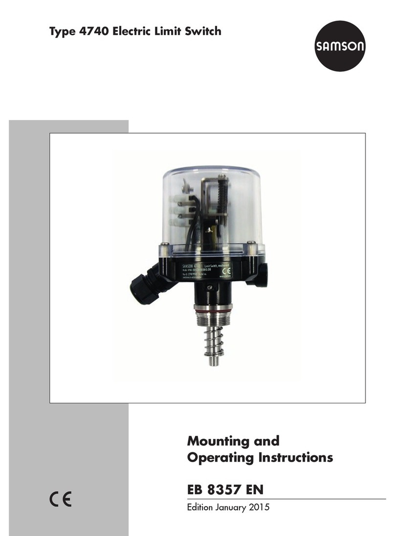
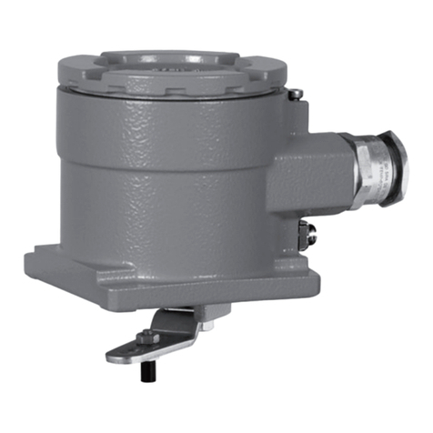
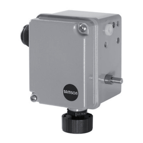
Samson 3738-50 Service manual

Mounting and
Operating Instructions
EB 8390-5 EN
Firmware version A 1.01 / K 1.01
Edition August 2016
Type 3738-50 Electronic Limit Switch
with optional integrated solenoid valve
for valves used in on/off applications
FOUNDATION™ eldbus communication

Denition of signal words
DANGER!
Hazardous situations which, if not
avoided, will result in death or seri-
ous injury
WARNING!
Hazardous situations which, if not
avoided, could result in death or seri-
ous injury
NOTICE
Property damage message or mal-
function
Note:
Additional information
Tip:
Recommended action
2 EB 8390-5 EN

Contents
EB 8390-5 EN 3
1 Important safety instructions ..........................................................................6
2 Article code...................................................................................................7
3 Design and principle of operation ..................................................................8
3.1 Versions ........................................................................................................8
3.2 Communication using TROVIS-VIEW .............................................................10
3.3 FOUNDATION™eldbuscommunication......................................................10
3.3.1 FOUNDATION™eldbusblockmodel ..........................................................10
3.4 Safety-related information ............................................................................11
4 Technical data .............................................................................................12
4.1 Electronic limit switch ...................................................................................12
4.2 Solenoid valve .............................................................................................14
4.3 Forced venting option...................................................................................14
5 Attachment .................................................................................................15
5.1 Accessories .................................................................................................16
5.2 Attachment to linear actuators.......................................................................17
5.2.1 Preparations ................................................................................................17
5.2.2 Attachment..................................................................................................18
5.3 Attachment to rotary actuators ......................................................................20
5.3.1 Preparations ................................................................................................21
5.3.2 Attachment..................................................................................................22
6 Connections ................................................................................................26
6.1 Pneumatic connections..................................................................................26
6.2 Supply pressure ...........................................................................................27
6.3 Electrical connection.....................................................................................27
7 Operator controls and readings ...................................................................30
7.1 Rotarypushbutton........................................................................................30
7.2 SAMSON SSP interface................................................................................30
7.3 Local operation............................................................................................30
8 Start-up ......................................................................................................33
8.1 Adapting the display direction ......................................................................33
8.2 Verifying readings on display........................................................................33

4 EB 8390-5 EN
Contents
8.3 Determining the actuator type .......................................................................34
8.4 Determining the direction of action................................................................35
8.5 Adjusting the end positions...........................................................................35
8.6 Initialization ................................................................................................36
8.6.1 Start automatic initialization .........................................................................37
8.6.2 Start manual initialization.............................................................................37
8.7 Replacing an electronic limit switch................................................................39
8.8 Zero/endpositioncalibration .......................................................................39
8.9 Reset to default settings.................................................................................40
9 Operation...................................................................................................40
9.1 Lockoperation.............................................................................................40
9.1.1 LockingoperationoverFOUNDATION™eldbus...........................................40
9.1.2 Locklocaloperation .....................................................................................41
9.2 Partialstroketest(PST)..................................................................................41
9.2.1 DeningthePSTtargetrange........................................................................43
9.2.2 Startingthepartialstroketest........................................................................43
9.2.3 CongurationexamplebasedonPTOdirectionofaction ................................44
9.3 Testing the solenoid valve..............................................................................47
9.4 Fault ...........................................................................................................47
9.4.1 Status messages...........................................................................................47
9.4.2 Error messages ............................................................................................48
9.4.3 Conrmingstatusanderrormessages ...........................................................48
10 Maintenance, calibration and work on equipment ........................................48
10.1 Maintenance ...............................................................................................48
11 Servicing explosion-protected devices ..........................................................49
12 Firmware update (serial interface)................................................................49
13 Parameter list..............................................................................................50
13.1 Status messages...........................................................................................54
13.2 Error messages ............................................................................................56
14 Dimensions in mm.......................................................................................58
Assignment based on the direction of action .................................................................71


6 EB 8390-5 EN
Important safety instructions
1 Important safety instructions
For your own safety, follow these instructions concerning the mounting, start up and opera-
tion of the electronic limit switch:
−Thedeviceistobemounted,starteduporoperatedonlybytrainedandexperienced
personnel familiar with the product. According to these mounting and operating instruc-
tions,trainedpersonnelisreferredtoasindividualswhoareabletojudgetheworkthey
areassignedtoandrecognizepossibledangersduetotheirspecializedtraining,their
knowledgeandexperienceaswellastheirknowledgeoftheapplicablestandards.
−Explosion-protectedversionsofthisdevicearetobeoperatedonlybypersonnelwhohas
undergonespecialtrainingorinstructionsorwhoisauthorizedtoworkonexplosion-pro-
tected devices in hazardous areas.
−Anyhazardsthatcouldbecausedbymovingpartsaretobepreventedbymeansofthe
appropriate measures.
−Forusewithinhazardousareas,theSpecialConditionsmentionedintheECtypeexami-
nationcerticateanditsaddendamustbeobserved.
−Ifinadmissiblemotionsorforcesareproducedinthepneumaticactuatorasaresultof
thesupplypressurelevel,itmustberestrictedusingasuitablesupplypressurereducing
station.
To avoid damage to any equipment, the following also applies:
−Proper shipping and storage are assumed.
−Do not ground electric welding equipment near to the electronic limit switch.
Note:
The device with a CE marking fullls the requirements of the Directive 2004/108/EC.

EB 8390-5 EN 7
Article code
2 Article code
Electronic Limit Switch Type 3738-50- xxxxx0 0 x1x0 0 x0
With LCD
Explosionprotection
Without 0 0 0
II2GExiaIICT6;II2DExiaIIICT80°CIP66 110
II2GExeb[ia]IICT4;II2DExtbIIICT80°CIP66 310
II3GExicIICT4;II3GExnAIIT4Gc;II3DExtcIIICT80°CIP66 810
Solenoid valve
External,bus-powered 0
Integrated,bus-powered 4
Options
Without 0
Forced venting 1
Company version
SAMSON 0
AIR TORQUE 1
Cover
Graybeige 0 0
Black 0 1
Silver gray 1 3
Special applications
Without 0
Versioncompatiblewithpaint 1
Special version
Without 0

8 EB 8390-5 EN
Design and principle of operation
3 Design and principle of oper-
ation
TheType3738-50ElectronicLimitSwitchal-
lowson/offvalvestobeactuatedbyaninte-
gratedorexternalsolenoidvalveaswellas
theirdiscreteendpositionstobereadoutby
a FOUNDATION™eldbusnetworkaccording
toIEC61158-2.
Major features of the electronic limit switch
include:
−PowersuppliedbyaFOUNDATION™eld-
busnetwork(solenoidvalvewithlowener-
gyconsumptionof6VDC)
−Simple discrete control of on/off valves
over a FOUNDATION™eldbusnetwork
−Integrateddiagnosticswithpartialstroke
testing(PST)
−Non-contact sensing of the rotation angle
byamagnetoresistivesensorsystem
−Version with integrated solenoid valve or
forexternalsolenoidvalve
Fig.1
The electronic limit switch is designed for at-
tachment to pneumatic actuators. The current
valve position is measured without contact
usingamagnet(onascrew)positionedcen-
trically on the actuator shaft. The screw with
magnetdoesnotneedtobeadjusted.The
AMR(anisotropicmagnetoresistive)sensor
located in the device together with the mea-
suringelectronics(1)candetectthedirec-
tionalchangeoftheappliedmagneticeld
and, as a result, sense the movement of the
actuator.
Thepneumaticactuatorisoperatedbyaso-
lenoidvalve(6,8)whichconvertsthesignal
issuedbytheprocesscontrolsystemintoa
binarypressuresignal.
3.1 Versions
Version with integrated solenoid valve
(Type 3738-50-xxx4x00x1x00x0)
The solenoid valve is integrated into the
housing of the electronic limit switch. The
electronic limit switch and the solenoid valve
arepoweredbytheconnectedFOUNDA-
TION™eldbustwo-wirecableaccordingto
IEC61158-2.
Theelectroniclimitswitchcanoptionallybe
ttedwithaforced venting function. This
function is activated when the solenoid valve
is de-energized after the power supply is in-
terrupted, causing the actuator to move the
control valve to its fail-safe position.
Version for external solenoid valve
(Type 3738-50-xxx0x00x1x00x0)
Theelectroniclimitswitchandtheexternal
solenoidvalvearepoweredbytheconnect-
ed FOUNDATION™eldbustwo-wirecable
accordingtoIEC61158-2.
Theelectroniclimitswitchcanoptionallybe
ttedwithaforced venting function. This
function is activated when the solenoid valve
is de-energized after the power supply is in-
terrupted, causing the actuator to move the
control valve to its fail-safe position.

EB 8390-5 EN 9
Design and principle of operation
T
SSP
interface
11 10
3FOUNDATION™
fieldbus
IEC 61158-2
2
5
8*
1
912
4
Signal for forced venting*
6
7
Electronic
limit switch
A
ctuator
1 AMR sensor with electronics
2 A/D converter
3 Microcontroller
4 Interfacemodule(IEC61158-2)
5 Actuation of forced venting
6 Solenoid valve
(Type3738-50-xxx4x00x1x00x0)
7 Aircapacitybooster
(Type
3738-50-xxx4x00x1x00x0
)
8*Externalsolenoidvalve
(Type
3738-50-xxx0x00x1x00x0
)
9 Electrical isolation
10 Display
11 Rotarypushbutton
12 Temperature sensor
* Optional
Fig.1: Schematic diagram – Type 3738-50 Electronic Limit Switch

10 EB 8390-5 EN
Design and principle of operation
3.2 Communication using
TROVIS-VIEW
SeeTable2onpage16forordernum-
bers.
Theelectroniclimitswitchcanbecongured
withSAMSON'sTROVIS-VIEWCongura-
tion and Operator Interface. The electronic
limit switch has for this purpose a SAMSON
SSP interface to allow the RS-232 or USB
portofacomputertobeconnectedtoitover
aserialinterfaceadaptercable.
TheTROVIS-VIEWsoftwareenablestheuser
toeasilyconguretheelectroniclimitswitch
as well as view and document process pa-
rameters on a computer. See Data Sheet
uT6661.
3.3 FOUNDATION™ eldbus
communication
The electronic limit switch is controlled com-
pletelybydigitalsignaltransmissionaccord-
ing to FOUNDATION™eldbusspecication.
Dataaretransmittedoverthebususingdigi-
tal,bit-synchronousManchestercodingata
baudrateof31.25kbit/sovertwisted-pair
wiresaccordingtoIEC61158-2.
Note:
If complex functions are started in the
electronic limit switch, which require
a long calculation time or lead to a
large quantity of data being saved in
the volatile memory of the electronic
limit switch, the alert 'busy' is issued
over the DD. This alert is not an error
message and can be simply con-
rmed.
3.3.1 FOUNDATION™
eldbus block model
All the functions and data of the electronic
limitswitchareassignedtovariousblock
types in FOUNDATION™eldbus.Eachblock
typecoversadifferentrangeoftasks.Inthe
SAMSONType3738-50ElectronicLimit
Switch,thefollowingblocktypesareimple-
mented:
Resource Block (RES)
TheResourceBlock(RES)describescharac-
teristicsoftheeldbusdevice,suchasthe
devicename,manufacturernumberandse-
rialnumber.ThereisonlyoneResource
Blockinadevice.
Function Blocks (FB)
FunctionBlocksareresponsiblefortheway
aeldbusdeviceworks.Aeldbusapplica-
tioncanbeconguredbylinkingtheinput
andoutputparametersofFunctionBlocks.
The Type 3738-50 Electronic Limit Switch in-
cludesthefollowingFunctionBlocks:
5xDiscreteInputFunctionBlocks(DIFB);
executiontime:20ms
5xDiscreteOutputFunctionBlocks(DOFB);
executiontime:30ms
1xAnalogInputFunctionBlock(AIFB)
analogpositionfeedback;execution
time: 20 ms

EB 8390-5 EN 11
Design and principle of operation
Transducer Blocks (TRD)
EachAIorAOFunctionBlockhasaTrans-
ducerBlockwhichcontainsalldataandde-
vice-specicparameterstolinkthedeviceto
theprocessvalue(sensorornalcontrolele-
ment).
ThefollowingTransducerBlocks(correspond-
ingtotheFunctionBlocks)areimplemented:
5x DiscreteInputTransducerBlocks(DITRD)
5x
DiscreteOutputTransducerBlocks(DO
TRD)
1x AnalogInputTransducerBlock(AITRD)
Note:
The parameter of the individual func-
tion blocks are described in the Con-
guration Manual KH8390-5.
3.4 Safety-related information
The Type 3738-50 Electronic Limit Switch
was developed to meet the requirements stip-
ulated in IEC 61508. The safety-related data
are listed in the Manufacturer’s Declaration
HE1258.
Safety-related assumptions
Emergency venting
When the optional forced venting function is
used,aninterruptedvoltagesignal(24V)at
terminals87/88causesthebus-poweredin-
tegratedorexternalsolenoidvalvetobede-
energized, venting the mounted actuator. The
functionissuitablefortheuseinsafety-in-
strumentedsystemsaccordingtoIEC61508.
The emergency venting function is not affect-
edbythesoftwareortheselecteddevicepa-
rameters.
Requirements
−Short mean time to repair compared to
the average rate of demand
−Normalexposuretoindustrialenviron-
mentanduids
−Theuserisresponsibleforensuringthat
the device is used as intended.
Useful lifetime
AccordingtoIEC61508-2,section7.4.9.5,
ausefullifetimeof8to12yearscanbeas-
sumed.Othervaluescanbeusedbasedon
theuser’sexperience.
Notes concerning diagnostics
−Diagnostics are performed cyclically in-
sidethedevice.Criticalerrors(deviceer-
rorE9)aretransferredbyaDiscreteIn-
putFunctionBlockovertheFOUNDA-
TION™eldbusnetwork.Existingerrors
mustberemediedasdescribedinthese
Mounting and Operating Instructions. If
thisisnotpossible,theelectroniclimit
switchmustnotbeusedinsafetyloops.
−The proper functioning of the display
canbeveriedoverP3parameter.Refer
to section 8.2.
−The correct setting of all parameters must
beveriedbeforeeverystart-up.
Proof testing
Theforcedventingofthesolenoidvalve(ter-
minals87/88)needtobeactivatedforthe
proof test. The correct switching of the sole-

12 EB 8390-5 EN
Technical data
noid valve and the venting of the actuator
mustbemonitoredandconrmed.
Intended use
Thespecicationsandinformationintheda-
tasheetandintheseinstructionsmustbeob-
served.
Note concerning diagnosis of connected so-
lenoid valve and actuator
The diagnostics functions performed in the
device, e.g. actuator transit time monitoring,
aresuitablefordiagnosisofconnectedde-
vices, such as solenoid valve, pneumatic ac-
tuator and valve.
Repairs
Devices which are used in safety-instrument-
edsystemsmustberepairedbythemanu-
facturer.
4 Technical data
4.1 Electronic limit switch
Type 3738-50-xxx4x00x1x00x0 3738-50-xxx0x00x1x00x0
Version With integrated solenoid valve Forexternalsolenoidvalve
Permissiblerangeofrotation Min.:0to30°Max.:0to170°
Commu-
nication
Local SAMSON SSP interface with serial interface adapter with TROVIS-
VIEWwithdatabasemodule3738-50
Overbus FOUNDATION™eldbus
Supply
air
Supply presure 2.4to8bar Sameasspecicationsofthesole-
noid valve manufacturer
Air quality Acc. to ISO 8573-1 edition
2004
Max.particlesizeanddensity:
Class 4
Oil content: Class 3
Pressure dew point: Class 3 or
atleast10Kbelowthelowest
ambienttemperaturetobe
expected
Sameasspecicationsofthesole-
noid valve manufacturer
Air consumption In neutral position: <60 l/h
In switching position: <30 l/h
Electric power supply PoweredbyFOUNDATION™eldbus

EB 8390-5 EN 13
Technical data
Type 3738-50-xxx4x00x1x00x0 3738-50-xxx0x00x1x00x0
Version With integrated solenoid valve Forexternalsolenoidvalve
Maximumoperatingcurrent 14 mA
Permissibleambient
temperature
–25to80°C –40to80°C
Metalcableglandsmustbeusedforambienttemperaturesbelow
–20°C.
Thelimitsspeciedintheexaminationcerticateadditionallyapply.
Inuenc-
es
Temperature ±0.7%/90°angleabovethepermissibletemperaturerange
Inuenceof
vibrations 0.25 % up to 2500 Hz and 4 g according to IEC 770
Electromagneticcompatibility Complying with EN 61000-6-2, EN 61000-6-3, EN 61326-1 and
NAMUR Recommendation NE 21
Electrical connections M20x1.5cablegland(s)for6to12mmclampingrange,screw
terminalsfor0.2to2.5mm²wirecross-sections
*Without forced venting
*With forced venting
Onecablegland
Twocableglands
Twocableglands
Threecableglands
Materi-
als
Housing Die-castaluminumENAC-AlSi12(Fe)(ENAC-44300)acc.to
DINEN1706,powderpaintcoated
Housing cover PC
Covergasket PU
Indicator wheel PC
Magnet material Hard ferrite
Weight Approx.1.2kg Approx.1.0kg

14 EB 8390-5 EN
Technical data
Table1: Explosion protection certicates for Type 3738-20 Electronic Limit Switch
Type Certication Type of protection
3738-50
-110
EC type
examination
certicate
Number PTB08ATEX2039X II2GExiaIICT6;
II2DExiaIIICT80°CIP66
Date 2012-02-02
-113
Number
RU
C-DE.08.B.00114 1ExiaIICT6/T5/T4GaX;
ExtbIIICT80°CDbXDate 2013-11-15
Valid until 2018-11-14
-310
EC type
examination
certicate
Number PTB08ATEX2039X II2GExeb[ia]IICT4;
II2DExtbIIICT80°CIP66
Date 2012-02-02
-313
Number
RU
C-DE.08.B.00114 1Exe[ia]IICT4GbX;
ExtbIIICT80°CDbXDate 2013-11-15
Valid until 2018-11-14
-810
EC type
examination
certicate
Number PTB08ATEX2039X II3GExicIICT4;
II3GExnAIIT4Gc;
II3DExtcIIICT80°CIP66
Date 2012-02-02
4.2 Solenoid valve
Integrated solenoid valve (Type 3738-50-xxx4x00x1x00x0)
Version 3/2-way or 5/2-way function
Functiondeterminedbythepositionofthemoldedseal
KVS coefcient 0.32
Service life 1,000,000 switching cycles
Temperaturerange(operation) –25to+80°C
External solenoid valve (Type 3738-50-xxx0x00x1x00x0)
Readmanufacturer’sspecications!
6VDC,max.18mW
4.3 Forced venting option
Input 0to30VDCreversepolarityprotection·Staticdestructionlimit40V
Powerconsumption3.5mAat24Vwithgalvanicisolation
Signal Signal ‘1’ at Ue>5V·Signal‘0’atUe<3V

EB 8390-5 EN 15
Attachment
5 Attachment
DANGER!
−Electrostatic charging
Due to the high surface resistance
of the housing cover (RIsol.≥
109Ω), installation and mainte-
nance on the equipment must be
performed in such a way that elec-
trostatic charging cannot occur.
−Mechanical effects
In areas where damage to the
housing can be expected due to
mechanical inuences, the housing
must be protected by an additional
cover.
−Combustible dust atmospheres
The electronic limit switch complies
with the requirements for type of
protection Ex tb as the enclosure
(housing) is designed according to
EN60079-31. The housing has the
degree of protection IP66 accord-
ing to IEC60529.
WARNING!
Mount the electronic limit switch,
keeping the following sequence:
−Mount the electronic limit switch on
the actuator. Refer to section 5.2
and 5.3.
−Connect the supply air. Refer to
section 6.1 and 6.2.
−Connect the electrical power. Refer
to section 6.3.
−Perform the start-up settings. Refer
to section 8.
NOTICE
Observe the following instructions to
avoid damaging the electronic limit
switch:
−Use only the accessories listed in
Table2 to mount the electronic limit
switch.
−Observe the shaft height of the ac-
tuator on mounting the electronic
limit switch on rotary actuators.
Mounting position
Anymountingpositionmaybeused,howev-
er,theelectroniclimitswitchmustnotbein-
stalled in a suspended position.

16 EB 8390-5 EN
Attachment
5.1 Accessories
Table2: Accessories
Order no.
Attachment to linear
actuators (NAMUR
attachment)
Version with integrated solenoid valve G ¼
Version with integrated solenoid valve ¼ NPT
1402-0540
1402-0541
Versionforexternalsolenoidvalve G¼
Versionforexternalsolenoidvalve ¼NPT
1402-0542
1402-0543
Plus mounting parts for Type 3271 Actuator
Versionupto700cm²
1400-60 and 2800-120 versions
2800-30 and 2800-60 versions
–
1402-0544
1402-0545
Attachment to rotary
actuators acc. to VDI/
VDE3845, xing level 1
(2010)
Attachment(20mmshaftheight)
Attachment(30mmshaftheight)
Attachment(50mmshaftheight)
Attachment(50mmshaftheight,88mmshaftdiame-
ter),e.g.AIRTORQUETypeSC3000orPfeifferType
31b,size2000
Attachment(80mmshaftheight)
1400-9859
1400-9860
1400-9861
1402-0332
1402-0586
Mountingplatform(black) G¼
Mountingplatform(black) ¼NPT
1380-1266
1380-1268
Mounting platform with piping as required G ¼
Mounting platform with piping as required ¼ NPT
1380-1738
1380-1739
TROVIS-VIEW Conguration
and Operator Interface soft-
ware
TROVIS-VIEWwithdevicemodule3738-50(freedownloadfrom
www.samson.de)
Serialinterfaceadapter(SAMSONSSPinterfaceto
RS-232portonaPC) 1400-7700
IsolatedUSBinterfaceadapter(SAMSONSSPinterface
toUSBportonaPC) 1400-9740

EB 8390-5 EN 17
Attachment
5.2 Attachment to linear actua-
tors
The electronic limit switch is mounted to lin-
earactuatorsaccordingtoIEC60534-6
(NAMURattachment).
Required accessories: seeTable2
5.2.1 Preparations
Version with integrated solenoid valve
(Type 3738-50-xxx4x00x1x00x0) (Fig.2)
1. Insertthemoldedseal(3)intothemount-
ingunit(2)dependingonthetypeofac-
tuator(single-actingordouble-acting).
2. PushtheO-ring(3.1)ontotheairductof
themoldedseal(3).
3. Fastentheelectroniclimitswitch(1)to
themountingunit(2)usingthetwo
screws mounted on the electronic limit
switchasshowninFig.2.
4. Removetheblankingplugonthesupply
airport(SUPPLY,2.1)ofthemounting
unit(2).
Version with external solenoid valve
(Type 3738-50-xxx0x00x1x00x0)
1. Fastentheelectroniclimitswitch(1)to
themountingunit(2)usingthetwo
screws mounted on the electronic limit
switchasshowninFig.2.
Single-acting
3/2-way
Double-
acting
5/2-way
1
2
2.1
3.1 3
1 Electronic limit switch
2 Mounting unit
2.1 Supply air port
3 Molded seal
3.1 O-ring
Y1 Output signal pressure
Y2 Opposing signal pressure
Fig.2: Preparations for mounting the electronic limit switch with integrated solenoid valve

18 EB 8390-5 EN
Attachment
5.2.2 Attachment
Usethelever(5)underneaththemounting
unit(2)andthepin(6)onthelevertoadapt
the electronic limit switch to the linear actua-
tor.
Table3: Travel table
Actuator
size [cm²]
Rated
travel
[mm]
Lever Recommended
pin position
120 to 350 15 M 35
700 15/30 M 50
1400 60 L 100
2800 120 XL 200
2800 30 M 50
2800 60 L/XL 100/200
The electronic limit switch is equipped with
theleverM(pinposition35)asstandard.
LeversLandXLareincludedinthemounting
parts 1402-0544 or 1402-0545.
1. Selectlever(5)accordingtoTable3.
2. Insertthefollowerpin(6)intothepinpo-
sitionaccordingtoTable3ofthelever
(5).Fastentightusingthewashersand
nuts
(Fig.3)
.
3. Placethelever(5)ontheshaftofthe
mountingunit(2)andfastenittightusing
thediskspring(5.1)andnut(5.2).
4. Mounting to actuators with 120 to
700cm² actuator areas (Fig.4 1 ):
Fastenthefollowerplate(7.1)atthemid-
dleholestothestemconnector(9)ofthe
actuatorusingthewashers(7.2)and
screws(7.3).
Mounting to Type3271 Actuators with
1400 and 2800cm² actuator areas and
with 200mm rated travel (Fig.4 2)
Fastenthefollowerplate(7.4)attheout-
erholestothestemconnector(9)ofthe
actuatorusingthescrews(7.5).
Mounting to Type3271 Actuators with
2800cm² actuator area and with 50,
100 or 200mm rated travel (Fig.4 3 )
Screwthebracket(8)tothestemconnec-
tor(9)oftheactuatorusingthescrews
(8.2).
Fastenthefollowerplate(7.1)together
withpins(8.1)locatedinthemiddle
holestothebracket(8)usingthewashers
(7.2)andscrews(7.3).
5. Fastenthemountingunit(2)totheactua-
torusingthescrew(4),ensuringthatthe
followerpin(6)comestorestintheslot
ofthefollowerplate(7.1/7.4).
6. Electronic limit switch with integrated
solenoid valve: connect supply air to
supplyairport(SUPPLY,2.1).
6
6.2
6.2
6.1
5.2
5.1
5
5 Lever
5.1 Diskspring
5.2 Nut
6 Follower pin
6.1 Washer
6.2 Nut
Fig.3: Fastening the follower pin on the lever

EB 8390-5 EN 19
Attachment
3
1 Electronic limit switch
2 Mounting unit
2.1 Supplyairport(SUPPLY)
4 Screw
5 Lever
5.1 Diskspring
5.2 Nut
6 Follower pin
6.1 Washer
6.2 Nut
7.1 Follower plate
7.2 Washer
7.3 Screws
7.4 Follower plate
7.5 Screws
8Bracket
8.1 Pin
8.2 Screws
9 Stem connector
7.3
7.2
8.1
7.1
8
8.2
7.5
7.4 7.3
7.2
7.1 9
5
5
6
6
2
4
1
2.1
6
5
2
1
Fig.4: Mounting the electronic limit switch on linear actuators

20 EB 8390-5 EN
Attachment
Required accessories: seeTable2
Versions with integrated solenoid valve
(Type 3738-50-xxx4x00x1x00x0)
Version for external solenoid valve
(Type 3738-50-xxx0x00x1x00x0)
Actuator surface
A
*C
M 6
B
30
Ø 5.5
Actuator surface
ShaftheightB [mm] 20 30 50
DistancebetweenholesA [mm] 80 80/130 130
Fig.5: Mounting to rotary actuators according to VDI/VDE3845, level 1 (2010)
5.3
Attachment to rotary actuators
TheelectroniclimitswitchismountedonrotaryactuatorsaccordingtoVDI/VDE3845,lev-
el1(2010).TheversionwithintegratedsolenoidvalvecanbedirectlymountedtoaPfeiffer
Type31bRotaryActuator.
Other manuals for 3738-50
1
Table of contents
Other Samson Switch manuals

Samson
Samson 4740 Service manual

Samson
Samson EB 3773 Series Service manual

Samson
Samson 3768 Service manual

Samson
Samson 4746 Service manual

Samson
Samson 4747 Service manual

Samson
Samson 4746 Service manual

Samson
Samson 3738-20 Service manual

Samson
Samson 3738-50 Instruction sheet

Samson
Samson 4747 Service manual

Samson
Samson 3776 Service manual
Popular Switch manuals by other brands

Avea
Avea Kramer VP Series Connection guide

Asus
Asus GX1026 quick start guide

Philips
Philips PCUH411 Specifications

Allied Telesis
Allied Telesis SwitchBlade AT-SB4008 supplementary guide

Extreme Networks
Extreme Networks 8520 Series Hardware installation guide

Lantech
Lantech 5 10/100TX w/ 4 PoE Injector Industrial... user manual