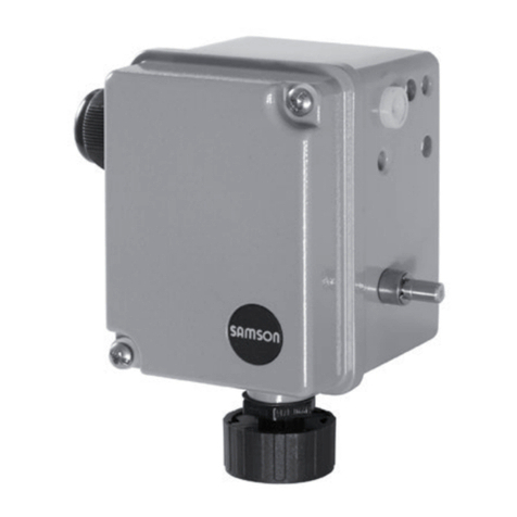
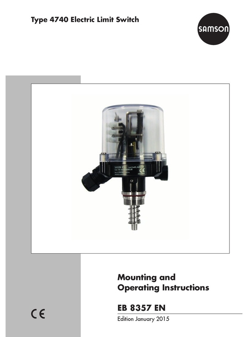
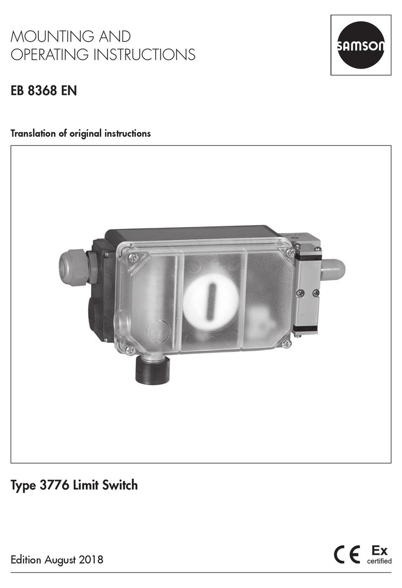
Samson EB 3773 Series Service manual

Translation of original instructions
EB 3773 EN
Edition November 2021
Type3773 Limit Switch

Note on these mounting and operating instructions
These mounting and operating instructions assist you in mounting and operating the device
safely. The instructions are binding for handling SAMSON devices. The images shown in
these instructions are for illustration purposes only. The actual product may vary.
ÎFor the safe and proper use of these instructions, read them carefully and keep them for
later reference.
ÎIf you have any questions about these instructions, contact SAMSON‘s After-sales Service
(aftersalesservice@samsongroup.com).
Documents relating to the device, such as the mounting and operating
instructions, are available on our website at www.samsongroup.com >
Service & Support > Downloads > Documentation.
Definition of signal words
Hazardous situations which, if not avoided,
will result in death or serious injury
Hazardous situations which, if not avoided,
could result in death or serious injury
Property damage message or malfunction
Additional information
Recommended action
DANGER
!
WARNING
!
NOTICE
!
Note
Tip
EB 3773 EN

Contents
EB 3773 EN
1 Safety instructions and measures ................................................................1-1
1.1 Notes on possible severe personal injury ......................................................1-3
1.2 Notes on possible personal injury ................................................................1-3
1.3 Notes on possible property damage.............................................................1-4
2 Markings on the device ..............................................................................2-1
2.1 Nameplate .................................................................................................2-1
2.2 Article code................................................................................................2-2
3 Design and principle of operation ...............................................................3-1
3.1 Technical data ............................................................................................3-3
3.2 Dimensions in mm.......................................................................................3-6
4 Shipment and on-site transport ...................................................................4-1
4.1 Accepting the delivered goods .....................................................................4-1
4.2 Removing the packaging from the limit switch ...............................................4-1
4.3 Transporting the limit switch.........................................................................4-1
4.4 Storing the limit switch.................................................................................4-1
5 Installation.................................................................................................5-1
5.1 Installation conditions..................................................................................5-1
5.2 Preparation for installation...........................................................................5-1
5.3 Mounting the limit switch .............................................................................5-2
5.3.1 AttachmentaccordingtoVDI/VDE3845,level1...........................................5-2
5.3.2 AttachmentaccordingtoVDI/VDE3845,level2...........................................5-2
5.4 Electrical connections ..................................................................................5-3
6 Start-up .....................................................................................................6-1
6.1 Adjusting the limit contacts ..........................................................................6-1
7 Operation..................................................................................................7-1
8 Malfunction................................................................................................8-1
8.1 Emergencyaction .......................................................................................8-1
9 Servicing....................................................................................................9-1
9.1 Servicing explosion-protected devices...........................................................9-2
9.2 Maintenance, calibration and work on equipment .........................................9-2
9.3 Preparation for return shipment....................................................................9-3
9.4 Cleaning the housing cover..........................................................................9-3
9.5 Periodic inspection and testing of the limit switch ...........................................9-3
10 Decommissioning .....................................................................................10-1
11 Removal ..................................................................................................11-1
Contents
EB 3773 EN
12 Repairs ....................................................................................................12-1
12.1 Returning devices to SAMSON ..................................................................12-1
13 Disposal...................................................................................................13-1
14 Certicates and instructions concerning explosion protection......................14-1
14.1 Certicates ...............................................................................................14-1
14.2 Instructions concerning explosion protection................................................14-1
15 Annex......................................................................................................15-1
15.1 After-sales service.....................................................................................15-1

EB 3773 EN 1-1
Safety instructions and measures
1 Safety instructions and measures
Intended use
TheSAMSONType3773LimitSwitchismountedonpneumaticrotaryactuatorsaccording
toVDI/VDE3845.Itissuesanelectricsignalwhenthevalvetravelexceedsorfallsbelowan
adjusted limit. The signal is suitable for switching control signals, issuing visual and audible
alarms or for connection to central control or alarm systems. The device is designed to oper-
ateunderexactlydenedconditions(e.g.temperature).Therefore,operatorsmustensurethat
the limit switch is only used in applications where the operating conditions correspond to the
technical data. In case operators intend to use the limit switch in other applications or condi-
tionsthanspecied,contactSAMSON.
SAMSON does not assume any liability for damage resulting from the failure to use the de-
vice for its intended purpose or for damage caused by external forces or any other external
factors.
ÎRefertothetechnicaldataforlimitsandeldsofapplicationaswellaspossibleuses.
Reasonably foreseeable misuse
TheType3773LimitSwitchisnot suitable for the following applications:
−Useoutsidethelimitsdenedduringsizingandbythetechnicaldata
Furthermore, the following activities do not comply with the intended use:
−Use of non-original spare parts
−Performing maintenance activities not described in these instructions
Qualications of operating personnel
Thelimitswitchmustbemounted,startedupandservicedbyfullytrainedandqualiedper-
sonnel only; the accepted industry codes and practices must be observed. According to these
mounting and operating instructions, trained personnel refers to individuals who are able to
judgetheworktheyareassignedtoandrecognizepossiblehazardsduetotheirspecialized
training, their knowledge and experience as well as their knowledge of the applicable stan-
dards.
Explosion-protected versions of this device must be operated only by personnel who has un-
dergonespecialtrainingorinstructionsorwhoisauthorizedtoworkonexplosion-protected
devicesinhazardousareas.

1-2 EB 3773 EN
Safety instructions and measures
Personal protective equipment
No personal protective equipment is required for the direct handling of the limit switch. Work
on the control valve may be necessary when mounting or removing the device.
ÎObservetherequirementsforpersonalprotectiveequipmentspeciedinthevalvedocu-
mentation.
ÎCheck with the plant operator for details on further protective equipment.
Revisions and other modications
Revisions,conversionsorothermodicationsoftheproductarenotauthorizedbySAMSON.
Theyareperformedattheuser'sownriskandmayleadtosafetyhazards,forexample.Fur-
thermore, the product may no longer meet the requirements for its intended use.
Warning against residual hazards
To avoid personal injury or property damage, plant operators and operating personnel must
preventhazardsthatcouldbecausedinthecontrolvalvebytheprocessmedium,theoperat-
ing pressure, the signal pressure or by moving parts by taking appropriate precautions. Plant
operatorsandoperatingpersonnelmustobserveallhazardstatements,warningandcaution
notes in these mounting and operating instructions, especially for installation, start-up and
service work.
Responsibilities of the operator
Operators are responsible for proper use and compliance with the safety regulations. Opera-
tors are obliged to provide these mounting and operating instructions to the operating per-
sonnel and to instruct them in proper operation. Furthermore, operators must ensure that op-
erating personnel or third parties are not exposed to any danger.
Responsibilities of operating personnel
Operating personnel must read and understand these mounting and operating instructions as
wellasthespeciedhazardstatements,warningandcautionnotes.Furthermore,theoperat-
ing personnel must be familiar with the applicable health, safety and accident prevention
regulations and comply with them.
Referenced documentation
The following documents apply in addition to these mounting and operating instructions:
−The mounting and operating instructions of the components on which the limit switch is
mounted (valve, actuator, valve accessories etc.).

EB 3773 EN 1-3
Safety instructions and measures
1.1 Notes on possible severe personal injury
DANGER
!
Risk of fatal injury due to the ignition of an explosive atmosphere.
Incorrect installation, operation or maintenance of the limit switch in potentially explo-
sive atmospheres may lead to ignition of the atmosphere and ultimately to death.
ÎFormountingandelectricalinstallationinhazardousareas,observetheexplosion
protection approvals as well as the relevant electrotechnical regulations and the ac-
cidentpreventionregulationsthatapplyinthecountryofuse.EN60079-14applies
in Europe: Electrical installations design, selection and erection
ÎInstallation, operation or maintenance of the limit switch must only be performed by
personnelwhohasundergonespecialtrainingorinstructionsorwhoisauthorized
toworkonexplosion-protecteddevicesinhazardousareas.
Risk of fatal injury as a result of electrostatic discharge at the housing.
The housing of the limit switch is made of polycarbonate and may become electrostatical-
ly charged when handled incorrectly. An electric spark generated by electrostatic dis-
charge may lead to ignition of a potentially explosive atmosphere and cause death.
ÎClean a device installed in dust atmospheres regularly.
ÎOnly use a damp cloth or wipes to clean the housing surface.
1.2 Notes on possible personal injury
WARNING
!
Incorrect electrical connection will render the explosion protection unsafe.
ÎAdhere to the terminal assignment and observe correct polarity.
ÎDo not undo the enameled screws.
ÎDonotexceedthemaximumpermissiblevalues(Ui,li,Pi,Ci,Li)speciedintheEU
typeexaminationcerticateswheninterconnectingintrinsicallysafeelectricalequip-
ment.

1-4 EB 3773 EN
Safety instructions and measures
1.3 Notes on possible property damage
NOTICE
!
Disruption to the process
ÎDo not mount or service the limit switch while the process is running and only after
isolating the plant by closing the shut-off valves.

EB 3773 EN 2-1
Markings on the device
2 Markings on the device
2.1 Nameplate
Model 3773-
Var.-ID Serial no.
SAMSON AG D-60314 Frankfurt Made in Germany
0044
* For further values see Addendum to EB 3773 EN
3773
Limit switch,
5
2
7
8
4
9
6
1 Degree of protection
2Limitcontactversion(mechanical/inductive)
3 Permissible contact load
4 Model number
5CongurationID
6 Serial number1)
7Type of protection for explosion-protected devices
8 MaximumvaluesoftheEUTypeExaminationCerticate
9Temperaturelimitsinthetestcerticatesforexplosion-protecteddevices
1) Thersttwoguresoftheserialnumberinreverseorderindicatetheyearofmanufactureofthelimitswitch
(example:serialnumber81xxxxxÎYearofmanufacture=2018).
Explosion-protected versionVersion without explosion protection
Model 3773-
Var.-ID
Serial no.
SAMSON AG , Germany Made in Germany
See technical data for ambient temperature
3773
Limit switch, inductive
5
4
1
6
Version with inductive proximity switches
Model 3773-
Var.-ID
Serial no.
SAMSON AG , Germany Made in Germany
See technical data for ambient temperature
3773
Limit switch, mechanical
5
4
13
6
Version with electric microswitches

2-2 EB 3773 EN
Markings on the device
2.2 Article code
Limit switch Type3773- x x x x x x x x x x 0xxx000x x
Explosion protection
Without 0 0 0
ATEX: II2GExiaIICT4/T6Gb
II 2D Ex ia IIIB T95°C Db 110
IECEx: Ex ia IIC T4/T6 Gb
Ex ia IIIB T95°C Db 111
Limitcontact
InductiveSC3,5-N0-WH(–40to+80°C) 0 2
InductiveSJ3,5-SN(–40to+80°C) 0 5
InductiveSJ3,5-S1N(–40to+80°C) 0 6
MicroswitchXGK19-88-S20
withsilvercontact(–40to+80°C) 2 0
MicroswitchXGK12-81-S20
withgoldcontact(–40to+80°C) 2 1
Number of contacts
Two contacts 2
Switching angle
<100° 0
Terminals
Screw terminals 1
Cage clamp terminals 2
Electrical threaded connections
M20x1.5 1
Degree of protection
IP65 0
Housing material
Black plastic (polyarylamide PA MXD6 – GF50) 0
Cover
Blue plastic (polycarbonate (PC) Makrolon®) 0

EB 3773 EN 2-3
Markings on the device
Limit switch Type3773- x x x x x x x x x x 0xxx000x x
Permissible ambient temperature
–25to+80°C(+65°CinT6) 0
Hardware version
Index: 00 9 9

2-4 EB 3773 EN

EB 3773 EN 3-1
Design and principle of operation
3 Design and principle of
operation
TheType3773LimitSwitchissuitablefor
mounting on rotary actuators according to
VDI/VDE3845,level1andlevel2.Itist-
ted with two inductive proximity switches or
two electric microswitches.
An adapter is used to connect the shaft (1) of
the limit switch to the actuator shaft. For most
applications the contacts are adjusted to is-
sue a signal when the actuator has reached
one of its end positions. Two adjustment
screws (3) are used to continuously adjust
the switching point to any position within the
angleofrotationtosignalizeanintermedi-
ate position.
Version with inductive proximity switches
The limit switch has adjustable metal tags (5)
on the shaft. When the tag is inside the mag-
neticeldoftheproximityswitch(4),the
proximity switch is attenuated and the output
has a high impedance (switching function
“Contact open”). When the tag leaves the
magneticeld,theproximityswitchisunat-
tenuated and the output has a low imped-
ance (switching function "Contact closed").
The tag can be adjusted to a switching point
between 0 and 100° at the adjustment screw
(3).
Version with electric microswitches
The limit switch has two adjustable cam disks
(7)ontheshaft.Thecamdiskactivatesthe
electric microswitch (6) over the roller on the
switch lever. The cam disks can be adjusted
to a switching point between 0 and 100° at
the adjustment screws (3).
Terminal versions
Dependingontheorderingspecications,
the limit switch has screw terminals or cage
clamp terminals.
3
2
1
2
3
Fig.3-1: Operating controls of the Type3773
Limit Switch

3-2 EB 3773 EN
Design and principle of operation
5
3
3
5
4
47
7
6 6
3
3
Version with inductive proximity
switches
Version with electric
microswitches
Fig.3-2: Versions of the Type3773 Limit Switch
Legend for Fig.3-1 and Fig.3-2:
1 Shaft
2 Terminals (screw terminals in this example)
3 Adjustment screws
4 Proximity switch
5 Metal tag
6 Microswitch
7Cam disk

EB 3773 EN 3-3
Design and principle of operation
3.1 Technical data
Table 3-1: Technical data of Type3773 Limit Switch
Type3773 Limit Switch
Angle of rotation 0 to 100°
Electromagnetic compatibility ComplyingwithEN61000-6-2,EN61000-6-3andNAMURRecommendation
NE21
Degree of protection IP65
Explosion protection Type of protection II 2/3 G/D Ex ia T6
Electrical connection 1x cable gland M20x1.5
Number of contacts 2
Permissible ambient temperature 1) –40to+80°C
Weight Approx.0.4kg
1) Observethetemperaturelimitsinthetestcerticateforexplosion-protectedversions.
Materials
Housing Polyarylamide PA MXD6 – GF50
Housing cover Polycarbonate (PC) Makrolon®
Follower shaft Polyoxymethylene (POM)
Housing breather Polyethersulfone on PET nonwoven fabric
Screws StainlesssteelA4-70
Terminals Polyamide 6.6
Table 3-2: Technical data of inductive proximity switches
Inductive proximity switches
Version -02 -04 -05
SC3,5-N0-WH SJ3,5-SN SJ3,5-S1N
Switching function NAMUR NC contact NAMUR NO contact
Switching accuracy in mm 0.06 to 0.1 <0.2 <0.3
Control circuit
Temperature1) –40to+80°C –40to+80°C –40to+80°C
Safety approval SILcapability

3-4 EB 3773 EN
Design and principle of operation
Limit contact in type of protection Ex ia IIC for use in hazardous areas (Zone 1)
Version -02 -04 -05
Output voltage Ui16VDC
Output current Ii52mA
Power dissipation Pi169mW
Outer capacitance Ci150nF 30nF
Outer inductance Li150µH 100µH
Temperature –40°C≤Ta≤+45°C
1) The permissible ambient temperature depends on the permissible ambient temperature of the components, type of
protection and temperature class.
ArestrictedtemperaturerangemayariseforSILapplications.
Table 3-3: Technical data of electric microswitches
Electric microswitches
Version -20 -21
XGK19-88-S20 XGK12-81-S20
Contact Silver contact Gold contact
Switching function Changeover contact/SPDT (single-pole/double-throw type)
Switching accuracy On request On request
Temperature1) –40to+80°C –40to+80°C
Permissible contact load 250VAC/10A
125VDC/0.5A
24VDC/10A
Safety approval – –
Limit switch in type of protection Ex nA II for use in hazardous areas (Zone 2 or 22)
Version -20 -21
Output voltage Ui28V
Output current Ii115mA
Power dissipation Pi500mW
Outer capacitance Ci0nF
Outer inductance Li0µH
Temperature –40°C≤Ta≤+80°C
1) The permissible ambient temperature depends on the permissible ambient temperature of the components, type of
protection and temperature class.
ArestrictedtemperaturerangemayariseforSILapplications.

EB 3773 EN 3-5
Design and principle of operation
Table 3-4: Summary of explosion protection approvals
Certication Type of protection/comments
Type3773
-110
EU type examina-
tioncerticate
Number TÜV18ATEX8323X II2GExiaIICT4/T6Gb
II 2D Ex ia IIIB T95°C Db
Date 2019-04-13
-111
IECEx Number IECEx TUR 19.0010X Ex ia IIC T4/T6 Gb
Ex ia IIIB T95°C Db
Date 2019-04-13

3-6 EB 3773 EN
Design and principle of operation
3.2 Dimensions in mm
94
8
119
~27109
88
88
40
51
5
88
55
50

EB 3773 EN 4-1
Shipment and on-site transport
4 Shipment and on-site trans-
port
The work described in this section is only to
be performed by personnel appropriately
qualiedtocarryoutsuchtasks.
4.1 Accepting the delivered
goods
After receiving the shipment, proceed as fol-
lows:
1. Check the scope of delivery. Check that
thespecicationsonthenameplateofthe
limitswitchmatchthespecicationsin
the delivery note. See the 'Markings on
the device' section for nameplate details.
2. Check the shipment for transportation
damage. Report any damage to
SAMSON and the forwarding agent
(refer to delivery note).
4.2 Removing the packaging
from the limit switch
Observe the following sequence:
ÎDo not remove the packaging until im-
mediately before installation of the limit
switch.
ÎDispose and recycle the packaging in
accordance with the local regulations.
4.3 Transporting the limit
switch
Transport instructions
−Protect the limit switch against external
inuences(e.g.impact).
−Protect the limit switch against moisture
and dirt.
−Observe transport temperature
depending on the permissible ambient
temperature (see the 'Design and
principle of operation' section).
4.4 Storing the limit switch
Risk of damage to the limit switch due to
improper storage.
ÎObserve the storage instructions.
ÎAvoid long storage times.
ÎContact SAMSON in case of different
storage conditions.
We recommend regularly checking the pre-
vailing storage conditions during long stor-
age periods.
Storage instructions
−Protect the limit switch against external
inuences(e.g.impact,shocks,vibra-
tion).
NOTICE
!
Note
!

4-2 EB 3773 EN
Shipment and on-site transport
−Do not damage the corrosion protection
(coating).
−Protect the limit switch against moisture
and dirt. In damp spaces, prevent con-
densation. If necessary, use a drying
agent or heating.
−Observe storage temperature depending
on the permissible ambient temperature
(see the 'Design and principle of opera-
tion' section).
−Do not place any objects on the limit
switch.
Table of contents
Other Samson Switch manuals

Samson
Samson 4747 Service manual

Samson
Samson 3738-50 Service manual

Samson
Samson 4746 Service manual

Samson
Samson 4746 Service manual

Samson
Samson 4747 Service manual

Samson
Samson 4740 Service manual

Samson
Samson 3738-50 Instruction sheet

Samson
Samson 3738-20 Service manual

Samson
Samson 3776 Service manual

Samson
Samson 3768 Service manual
Popular Switch manuals by other brands

Timeguard
Timeguard ZV210 operating instructions

Tripp Lite
Tripp Lite PDUMH15NET2 owner's manual

Uni-Com
Uni-Com GEP-32005T user manual

ITT
ITT neo-dyn 100p Installation and operation manual

Tripp Lite
Tripp Lite NetDirector B064-032-04-IPG Features and specifications

H3C
H3C S9500E Series Configuration guide