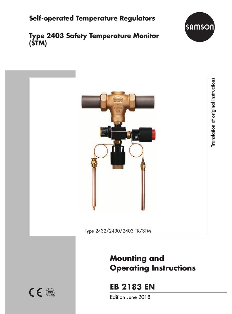
Samson 2439 Service manual

Translation of original instructions
EB 2185 EN
Edition August 2018
Type2439 Safety Temperature Limiter (STL)

Note on these mounting and operating instructions
These mounting and operating instructions assist you in mounting and operating the device
safely. The instructions are binding for handling SAMSON devices.
ÎFor the safe and proper use of these instructions, read them carefully and keep them for
later reference.
ÎIf you have any questions about these instructions, contact SAMSON‘s After-sales Service
Department (aftersalesser[email protected]).
The mounting and operating instructions for the devices are included in
the scope of delivery. The latest documentation is available on our website
at www.samson.de > Service & Support > Downloads > Documentation.
Denition of signal words
Hazardous situations which, if not avoided,
will result in death or serious injury
Hazardous situations which, if not avoided,
could result in death or serious injury
Property damage message or malfunction
Additional information
Recommended action
DANGER
!
WARNING
!
NOTICE
!
Note
Tip
2 EB 2185 EN

Contents
EB 2185 EN 3
1 Safety instructions and measures ...................................................................5
1.1 Notes on possible severe personal injury .........................................................8
1.2 Notes on possible personal injury ...................................................................8
1.3 Notes on possible property damage................................................................9
2 Markings on the device ...............................................................................11
2.1 Material number..........................................................................................11
3 Design and principle of operation ................................................................12
3.1 Technical data .............................................................................................14
3.2 Process medium and scope of application......................................................14
4 Measures for preparation............................................................................22
4.1 Unpacking ..................................................................................................22
4.2 Transporting and lifting ................................................................................22
4.3 Storage.......................................................................................................22
4.4 Preparation for installation............................................................................23
5 Mounting and start-up.................................................................................23
5.1 Assembling the safety temperature limiter and valve .......................................23
5.2 Additionalttings.........................................................................................24
5.3 Temperature sensor and capillary tube...........................................................25
5.4 Electric signal transmitter ..............................................................................26
5.4.1 Retrottingasignaltransmitter......................................................................26
5.5 Start-up.......................................................................................................26
5.5.1 Gases and liquids ........................................................................................27
5.5.2 Steam .........................................................................................................27
6 Operation...................................................................................................27
6.1 Adjusting the limit temperature......................................................................27
6.1.1 Adjusting the temperature limit without using a heating bath ...........................28
6.1.2 Adjusting the temperature limit using a heating bath.......................................28
6.2 Unlocking after a fault..................................................................................30
6.3 Sensor failure ..............................................................................................30
6.4 Maintenance ...............................................................................................31
6.5 Preparation for return shipment.....................................................................32
7 Malfunctions ...............................................................................................32
8 Decommissioning and removal ....................................................................34
8.1 Decommissioning.........................................................................................34
8.2 Disposal......................................................................................................34

Contents
4 EB 2185 EN
9 Appendix....................................................................................................35
9.1 After-sales service and spare parts ................................................................35
9.2 Tightening torques........................................................................................35
9.3 Certicates ..................................................................................................35

EB 2185 EN 5
Safety instructions and measures
1 Safety instructions and measures
Intended use
TheType2439SafetyTemperatureLimiter(STL)withvalveisdesignedfortemperaturemoni-
toring of the energy supply to heat generators (e.g. heat exchangers) by closing the valve.
TheconnectionofanadditionalType2430ControlThermostatconvertsthesafetytempera-
turelimiter(STL)intoatemperatureregulatorwithsafetytemperaturelimiter(TR/STL).
Thedevicesaredesignedtooperateunderexactlydenedconditions(e.g.operatingpres-
sure, process medium, temperature). Therefore, operators must ensure that the devices are
onlyusedinoperatingconditionsthatmeetthespecicationsusedforsizingthedevicesat
the ordering stage. In case operators intend to use the devices in other applications or condi-
tionsthanspecied,contactSAMSON.
SAMSON does not assume any liability for damage resulting from the failure to use the de-
vice for its intended purpose or for damage caused by external forces or any other external
factors.
ÎRefertothetechnicaldataandnameplateforlimitsandeldsofapplicationaswellas
possible uses.
Reasonably foreseeable misuse
Thedevicesarenotsuitableforuseoutsidethelimitsdenedduringsizingandbythetechni-
cal data. Furthermore, the following activities do not comply with the intended use:
−Use of non-original spare parts
−Performing service and repair work not described in these instructions
Qualications of operating personnel
The devices must be mounted, started up, serviced and repaired by fully trained and quali-
edpersonnelonly;theacceptedindustrycodesandpracticesaretobeobserved.Accord-
ing to these mounting and operating instructions, trained personnel refers to individuals who
areabletojudgetheworktheyareassignedtoandrecognizepossiblehazardsduetotheir
specializedtraining,theirknowledgeandexperienceaswellastheirknowledgeoftheappli-
cable standards.

6 EB 2185 EN
Safety instructions and measures
Personal protective equipment
Werecommendcheckingthehazardsposedbytheprocessmediumbeingused(e.g.
uGESTIS(CLP)hazardoussubstancedatabase).
ÎProvide protective equipment (e.g. safety gloves, eye protection) appropriate for the pro-
cess medium used.
ÎWear hearing protection when working near the valve.
ÎCheck with the plant operator for details on further protective equipment.
Revisions and other modications
Revisions,conversionsorothermodicationsoftheproductarenotauthorizedbySAMSON.
Theyareperformedattheuser'sownriskandmayleadtosafetyhazards,forexample.Fur-
thermore, the product may no longer meet the requirements for its intended use.
Warning against residual hazards
To avoid personal injury or property damage, plant operators and operating personnel must
preventhazardsthatcouldbecausedinthedevicebytheprocessmedium,theoperating
pressureorbymovingpartsbytakingappropriateprecautions.Theymustobserveallhaz-
ard statements, warning and caution notes in these mounting and operating instructions, es-
pecially for installation, start-up and service work.
Wealsorecommendcheckingthehazardsposedbytheprocessmediumbeingused(e.g.
uGESTIS(CLP)hazardoussubstancedatabase).
ÎObservesafetymeasuresforhandlingthedeviceaswellasrepreventionandexplosion
protection measures.
Responsibilities of the operator
The operator is responsible for proper operation and compliance with the safety regulations.
Operators are obliged to provide these mounting and operating instructions as well as the
referenced documents to the operating personnel and to instruct them in proper operation.
Furthermore, the operator must ensure that operating personnel or third persons are not ex-
posed to any danger.
Responsibilities of operating personnel
Operating personnel must read and understand these mounting and operating instructions as
wellasthereferenceddocumentsandobservethespeciedhazardstatements,warnings
and caution notes. Furthermore, the operating personnel must be familiar with the applicable
health, safety and accident prevention regulations and comply with them.

EB 2185 EN 7
Safety instructions and measures
Referenced standards and regulations
The devices comply with the requirements of the European Pressure Equipment Directive
2014/68/EU.DeviceswithaCEmarkinghaveanEUdeclarationofconformity,whichin-
cludes information about the applied conformity assessment procedure. This EU declaration
ofconformityisincludedintheAppendixoftheseinstructions(seesection9.3).
Non-electric valve versions whose bodies are not lined with an insulating material coating do
not have their own potential ignition source according to the risk assessment stipulated in
EN13463-1:2009,section5.2,evenintherareincidentofanoperatingfault.Therefore,
suchvalveversionsdonotfallwithinthescopeofDirective2014/34/EU.
ÎForconnectiontotheequipotentialbondingsystem,observetherequirementsspeciedin
section6.4ofEN60079-14(VDE0165Part1).
Referenced documentation
The following documents apply in addition to these mounting and operating instructions:
−Mounting and operating instructions for valves, e.g.
Type2431 and Type2432 uEB2171
Types2435, 2437 and 2436 uEB2172
Type2433 uEB2173
−Mounting and operating instructions for the control thermostat, e.g.
Type2430 uEB2430
uEB2430-3
−Mounting and operating instructions for the safety temperature monitor, e.g.
Type2403 uEB2183
−Mounting and operating instructions for the accessories, e.g.
Double adapter Do3 and
manual adjuster uEB2176

8 EB 2185 EN
Safety instructions and measures
1.1 Notes on possible severe personal injury
DANGER
!
Risk of bursting in pressure equipment.
Valvesandpipelinesarepressureequipment.Improperopeningcanleadtovalve
components bursting.
ÎBeforestartinganyworkonthevalve,depressurizeallplantsectionsconcernedas
well as the valve.
ÎDrain the process medium from all the plant sections concerned as well as the
valve.
ÎWear personal protective equipment.
1.2 Notes on possible personal injury
WARNING
!
Risk of personal injury due to residual process medium in the valve.
While working on the valve, residual process medium can escape and, depending on
its properties, may lead to personal injury, e.g. (chemical) burns.
ÎIf possible, drain the process medium from all the plant sections concerned and the
valve.
ÎWear protective clothing, safety gloves and eyewear.
Risk of burn injuries due to hot or cold components and pipelines.
Depending on the process medium, valve components and pipelines may get very hot
or cold and cause burn injuries.
ÎAllow components and pipelines to cool down or heat up.
ÎWear protective clothing and safety gloves.

EB 2185 EN 9
Safety instructions and measures
Damage to health relating to the REACH regulation.
If a SAMSON device contains a substance which is listed as being a substance of very
high concern on the candidate list of the REACH regulation, this circumstance is indi-
cated on the SAMSON delivery note.
ÎInformation on safe use of the part affected,
see uhttp://www.samson.de/reach-en.html.
1.3 Notes on possible property damage
NOTICE
!
Risk of valve damage due to unsuitable medium properties.
Thevalveisdesignedforaprocessmediumwithdenedproperties.
ÎOnlyusetheprocessmediumspeciedforsizing.
Risk of irreparable regulator damage caused by the regulator components being
taken apart.
The safety temperature limiter is an inseparable hydraulic unit consisting of a safety
thermostat, capillary tube and temperature sensor. If these components are dismantled
(e.g. removal of the capillary tube), the regulator will be irreparably damaged and will
nolongerbeabletofulllitsmonitoringandcontroltask.
ÎDo not dismantle the regulator.
ÎOnly perform allowed activities on the regulator.
ÎContact SAMSON's After-sales Service department before replacing spare parts.
Risk of valve damage due to contamination (e.g. solid particles) in the pipeline.
The plant operator is responsible for cleaning the pipelines in the plant.
ÎFlush the pipelines before start-up.
ÎObserve the maximum permissible pressure for valve and plant.

10 EB 2185 EN
Safety instructions and measures
Risk of damage to the valve or safety temperature limiter due to excessively high or
low tightening torques.
The connection between valve and safety temperature limiter must be tightened with a
certain tightening torque.
Excessively tightened torques lead to parts wearing out quicker. Parts that are too loose
may cause leakage.
ÎObservethespeciedtighteningtorques.

EB 2185 EN 11
Markings on the device
2 Markings on the device
Details on cap
12
4
5
2004
0062
3
1Type
2CongurationID
3CE marking
4Limitvaluerangein°Cand°F
5
Register number
(type test according to
DINEN14597)
Specications on
the valve Further information:
Valve Mounting and operating instructions
Type2431 for Type43-1 uEB2171
Type2432 for Type43-2
Type2433 for Type43-3 uEB2173
Type2435 for Type43-5
uEB2172Type2436 for Type43-6
Type2437 for Type43-7
Fig.1: Nameplates
2.1 Material number
SpecifyingthecongurationID,youcancontactustondoutwhichmaterialisused.The
congurationIDisspeciedonthenameplate(2,congurationID).
Formoredetailsonthenameplate,seeFig.1.

12 EB 2185 EN
Design and principle of operation
3 Design and principle of oper-
ation
See Fig.2.
The safety temperature limiter limits the tem-
perature by closing and locking a valve con-
nected to the thermostat. The safety tempera-
ture limiter works according to the adsorp-
tion principle (gas expansion). The tempera-
ture sensor (12), capillary tube (10) and op-
erating element (8) of the set point adjuster
arelledwithanexpansiongas.
The temperature-dependent change in vol-
ume of the gas in the bulb sensor (12) caus-
es the piston in the operating element (8) of
the set point adjuster to move. As a result,
the pin of the operating element moves the
plug stem (4) with the plug (3).
The temperature limit can be adjusted by
turning the set point adjuster (8). This limit
value is indicated on the scale (11).
The valve is locked by a spring mechanism
when the temperature reaches the adjustable
limit, when the capillary tube ruptures or
there is a leak in the sensor system.
The device can only be reset and put back
into operation when the fault has been reme-
died and the temperature has fallen below
thelimit(approx.15Kbelowtheadjusted
temperature limit).
Fail-safe position
The spring mechanism in the operating ele-
ment is released when the capillary tube
breaks or when there is a leak in the sensor.
It moves the plug stem (4) with the plug (3)
over the pin of the operating element and
closes and locks the valve. It is not possible
to unlock the valve if the capillary tube has
ruptured or there is a leak in the sensor sys-
tem.
The adjusted limit temperature must have a
minimum temperature difference of 15K to
the set point of the temperature regulator.
Note

EB 2185 EN 13
Design and principle of operation
1.1
V
2
3
4
5
15
15
TR
10
10
16
12
8
1234
11
13
17
18
19
STB
12
13
17
18
20
V Valve
STL Type2439SafetyTemperatureLimiter
TR Type2430ControlThermostat(optional)
1.1 Threaded ends or welding ends (optional)
2Valveseat
3 Plug
4 Plug stem
5 Plug spring
8 Operating element with set point adjuster
10 Capillary tube
11 Scale
12 Temperature sensor
13 Thermowell
15 Coupling nut
16 Openingforindication/unlocking
17 Screwtting
18 Packing
19 Opening for lead-sealing
20 Electric signal transmitter (optional)
Fig.2: Combination as temperature regulator with safety temperature limiter (TR/STL) and electric
signal transmitter
STL

14 EB 2185 EN
Design and principle of operation
3.1 Technical data
3.2 Process medium and scope
of application
Safety temperature monitoring of the energy
supply for heat generators or heat exchang-
ers by closing the valve
−Limitsignalsfrom10 to 120°C
−ValvesizeDN15 to 50
−PN16 to 25
−Max. 200°C
TheType2439SafetyTemperatureLimiter
(STL)withavalveoperateswithoutauxiliary
energy and is designed for extended safety
accordingtoDINEN14597.Thevalveis
closed by a spring mechanism when the
temperature reaches the adjusted limit, when
the capillary tube breaks or when leakage
occurs in the sensor system. The limiter can
only be unlocked and put back into
operation with a screwdriver after the fault
has been remedied and the temperature has
fallen below the limit.
Install the sensor together with the supplied
thermowell.
When the safety temperature limiter is com-
binedwithaType2430ControlThermostat,
make sure that there is a minimum difference
ofapproximately15Kbetweenthelimit
temperature of the temperature limiter and
the set point temperature of the control ther-
mostat.
Dimensions and weights
Fig.3providesasummaryofthedimensions
fortheType2439SafetyTemperatureLimiter
andtheTypes2431,2432,2433,2435,
2436and2437Valves.Thelengthsand
heights in the dimensional drawings are
shownonpage19onwards.
Typetesting
The safety temperature limiter combined with
the valve has been tested by the German
TechnicalInspectorate(TÜV)accordingto
DINEN14597underthetypedesignation
2750-1.
The registration number is available on re-
quest.
Further details and technical data of the
valves and control thermostats are listed in
the following mounting and operating in-
structions:
See Referenced documentation on
page7.
Note

EB 2185 EN 15
Design and principle of operation
Table1: Technical data· Type2439 Safety Temperature Limiter (STL)
Type 2439 Safety Temperature Limiter
Adjustment ranges of limit temperature 10to95°C·20to120°C
Permissible ambient temperature range at
the limit value adjuster 80°C·Withelectricsignaltransmitter60°C
Permissible temperature at sensor 20Kabovetheadjustedlimit
Permissible pressure at the sensor with
thermowell 40bar
Capillary tube length 2m·5m
Switching cycles according to
DINEN14597 500
Electric signal transmitter Max.load230V~,16Awithresistiveload
Compliance ·
Table2: Technical data·Types2431, 2432, 2433, 2435, 2436 and 2137 Valves
Valve Types2431, 2432, 2433, 2435, 2436 and 2137
Pressure rating PN16to25
Compliance ·
Connection size G ½ ¾ 1
Type2431 uT2171
Type2433 uT2173
Type2435·Type2436 uT2172
Valve size DN 15 20 25 32 40 50
Type2432 uT2171
Type2433 uT2173
Type2436·Type2437 uT2172

16 EB 2185 EN
Design and principle of operation
Table3: Female thread·Dimensions in mm and weights in kg · Type2431/2439,
Type2433/2439, Type2435/2439 and Type2436/2439
Connection
size G½ ¾ 1 ½ ¾ 1
Valve body CC499K 1.4408·A351 CF8M
Length L 65 75 90 65 75 90
Type2431/
2439
Height H 180 180
Height H1 30 50
Type2433/
2439
Height H 165
–
Height H1 40
Type2435/
2439
Height H 255
Height H1 30
Type2436/
2439
Height H 180 180
Height H1 30 50
Type2431/
2439 kg (approx.) 1.9 2.0 2.1 2.0 2.1 2.3
Type2433/
2439 kg (approx.) 2.1 2.2 2.3
–
Type2435/
2439 kg (approx.) 2.4 2.5 2.6
Type2436/
2439 kg (approx.) 2.3 2.4 2.5 2.1 2.2 2.4
Table4: Male thread·Dimensions in mm·Type2432/2439, Type2433/2439,
Type2436/2439 and Type2437/2439
Valve size DN 15 20 25 32 40 50
Valve body CC499K
Pipe Ø d 21.3 26.8 32.7 42.0 48.0 60.0
AF 30 36 46 59 65 82
Length L 65 70 90 100 110 130
Lengthwith
welding ends L1 210 234 244 268 294 330
Lengthwith
threaded ends L2 129 144 159 180 196 228
Male thread A G½ G¾ G1 G1¼ G1½ G2

EB 2185 EN 17
Design and principle of operation
Table4: Male thread·Dimensions in mm·Type2432/2439, Type2433/2439,
Type2436/2439 and Type2437/2439
Valve size DN 15 20 25 32 40 50
Type2432/
2439
Height H 175 225
Height H1 30 55
Type2433/
2439
Height H 171 181
Height H2 112 122 124 144 157 165
Height H3 72 77 82 105 110 115
Type2436/
2439
Height H –195
Height H1 95
Type2437/
2439
Height H 255 305
Height H1 30 55
Table5: Male thread·Weights in kg·Type2432/2439, Type2433/2439,
Type2436/2439 and Type2437/2439
Valve size DN 15 20 25 32 40 50
Valve body CC499K
Type2432/
2439 with …
Welding ends 2.2 2.5 2.8 4.9 5.5 7.3
Threaded ends 2.1 2.4 2.7 4.7 5.4 7.3
Type2433/
2439 with …
Welding ends 2.8 3.1 3.3 4.6 4.9 6.2
Threaded ends 2.8 3.1 3.3 4.6 4.9 6.2
Type2436/
2439 with …
Welding ends –3.8 4.2 4.6
Threaded ends 3.8 4.2 4.6
Type2437/
2439 with …
Welding ends 2.4 2.7 3.0 5.2 5.9 7.8
Threaded ends 2.3 2.6 2.9 5.5 5.9 7.8

18 EB 2185 EN
Design and principle of operation
Table6: Flanges·Dimensions in mm·Type2432/2439, Type2433/2439,
Type2436/2439 and Type2437/2439
Valve size DN 15 20 25 32 40 50
Length L3 130 150 160 180 200 230
Valve body CC499K1)
Type2433/2439 Height H 171 181
Height H4 72 80 82 105 110 115
Valve body EN-GJS-400-18-LT2)
Type2432/2439 Height H 180 230
Type2436/2439 Height H 180 230
Type2437/2439 Height H 260 310
Valve body 1.4408·A351 CF8M2)
Type2432/2439 Height H 180 –180 –
Type2436/2439 Height H 180 180
1) Withscrewed-onanges
2) Withangedbody
Table7: Flanges·Weights in kg·Type2432/2439, Type2433/2439, Type2436/2439
and Type2437/2439
Valve size DN 15 20 25 32 40 50
Valve body
Type2432/
2439
EN-GJS-400-18-LT 3.9 4.4 5.0 8.2 9.7 11.6
1.4408·A351CF8M – –
Type2433/
2439 CC499K 4.9 6.1 7.1 9.4 10.9 13.7
Type2436/
2439
EN-GJS-400-18-LT 4.0 4.6 5.1 8.3 9.8 11.7
1.4408·A351CF8M – –
Type2437/
2439 EN-GJS-400-18-LT 4.0 4.7 5.1 8.3 10.0 11.3

EB 2185 EN 19
Design and principle of operation
Table8: Dimensions in mm · Weights in kg·Type2439 and Type2430
Type2439 Safety Temperature Limiter·Type2430 Control Thermostat
Valve size G½ to G1·DN15 to 25 DN32 to 50
Type2439
Height H4 130
LengthL5 185
LengthB 210
LengthB1 190
GG½
M M32x1.5
ØT 12
Type2430
Height H6 130
LengthL5 185 220
GG½ G¾
ØT 12 19
Type2439 kg (approx.) 1.2
Type2430 kg (approx.) 0.9
Dimensional drawings
H1
L
H
L1
L
H
H1
d
SW
L2
L
H
H1
A
SW
L3
H
2431/2439
Female thread
2432/2439
With welding ends
2432/2439
With threaded ends
2432/2439
Flanged body
Fig.3: Dimensional drawings for Type2439

20 EB 2185 EN
Design and principle of operation
Dimensional drawings
L
H1
H
L1
L
d
SW
H
H2
H
L2
L
A
SW
H3
L3
H4
SW
H
2433/2439
Female thread
2433/2439
With welding ends
2433/2439
With threaded ends
2433/2439
With screwed-on
anges
H1
L
H
L
H
H1
L1
L
H
H1
d
SW
L2
L
H
H1
A
SW
2435/2439
Female thread
2436/2439
Female thread
2436/2439
With welding ends
2436/2439
With threaded ends
L3
H
L1
L
H1
d
H
SW
L2
L
H1
A
H
SW
L3
H
2436/2439
Flanged body
2437/2439
With welding ends
2437/2439
With threaded ends
2437/2439
Flanged body
Fig.3: Dimensional drawings for Type2439
Table of contents
Other Samson Temperature Controllers manuals