Samsung MWR-WW10N User manual

Air to Water Heat Pump
Inst al lat ion manual
Wired remote controller MWR-WW10N
࡛Thank you for purchasing t his Samsung Product.
࡛Before operating this unit , please read t his installation manual carefully and retain it for
f ut ur e r ef erence.

2English
Cont ent s
Safet y Information 3
Safety Information 3
Wired Remot e Cont rol ler Inst all at ion 4
Wired Remote Cont roller Installation 4
External Dimensions 4
Wired Remote Controller Installation 5
Tracking Your Indoor Unit from the Wired Remote Cont roller [See the image A] 8
Individual control wit h your wired remote controller 9
Gr oup con t rol wit h you r wi red r em ot e cont r ol ler 10
Cont rolling 2-remote cont roller 11
Sharing the temperature of hot water t ank sensor 12
Initializing Your Wired Remot e Cont roller Communicat ion 14
Errors displayed on the Wired Remote Cont roller 14
Inst all at ion/ Service mode 15
Installation/ Service mode 15
Addit ional functions of t he Wired Remote Controller [See t he image B] 15
Installation/ Service mode 16
The example of Wired Remot e Controller opt ion setting method 21
How to download t o microSD Card 21
Self-test mode of wired remot e cont roller 23
Use of self-t est mode [See the image D] 23
The lowest set temperature is limited t o 20 degree in the UAE according to UAE.S 5010-5:2016.

Safet y Informat ion
3
English
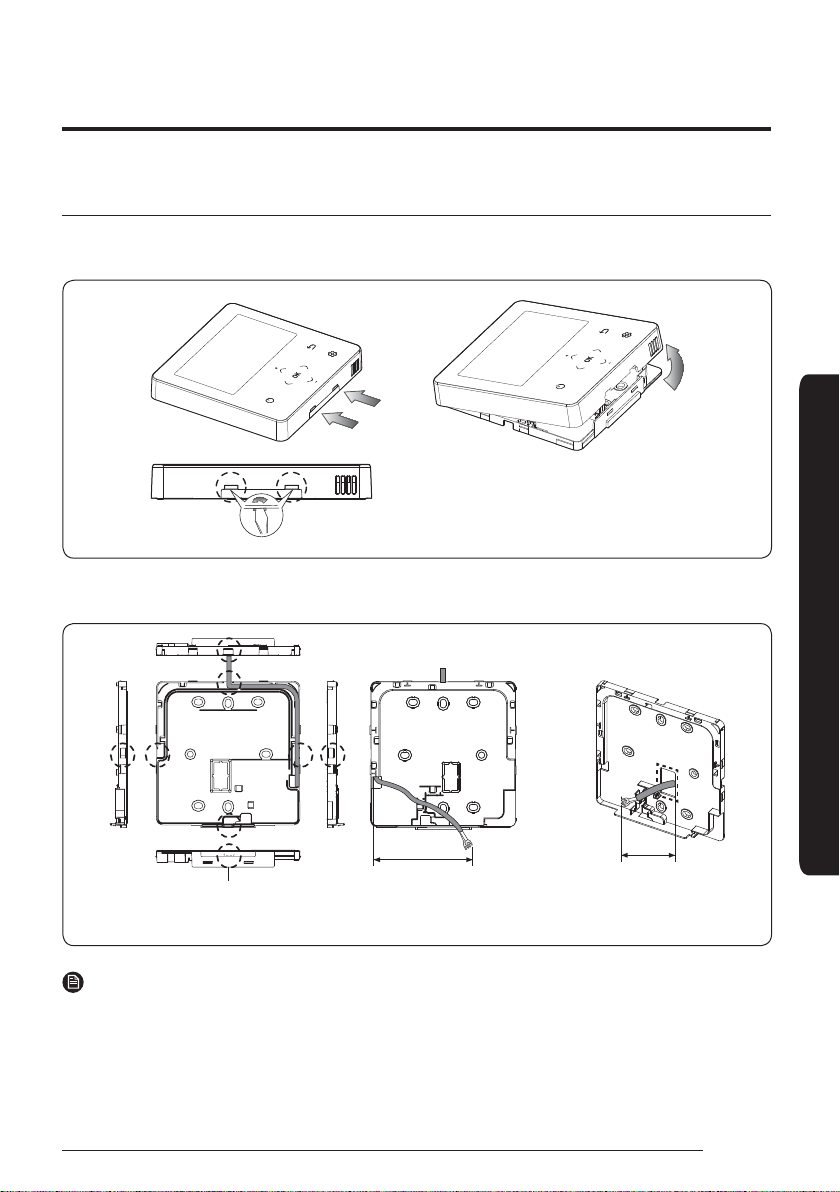
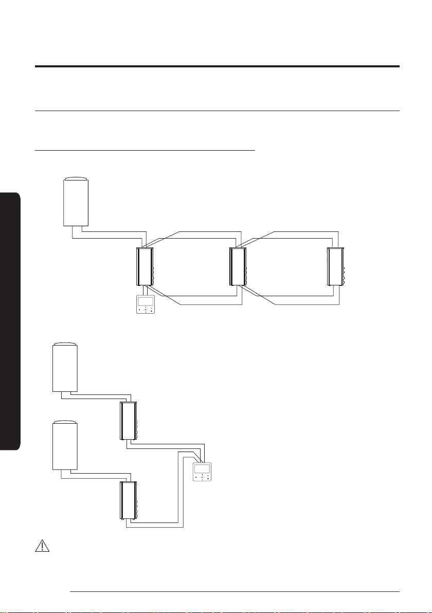
This installation manual explains how to install a Wired Remote Controller connected to the indoor unit of your
Samsung system air conditioner. Please read t his manual t horoughly before installing the product. (Please refer t o
appropriate installation for any optional product installat ion.)
Safet y Informat ion
WARNING
Hazards or unsafe practices that may result in severe personal injury or death.
CAUTION
Hazards or unsafe practices that may result minor personal injury or propert y damage.
WARNING
Cont act a service centre for installation.
࡛Potent ial risk of malfunction, water leak, electric
shock and fire.
Install t he product on a hard and even place that can
support it s weight .
࡛If the place cannot support it s weight, the product
may fall down and it may cause product damage.
Install t he product wit h proper power supply.
࡛Potent ial risk of fire or product damage.
Do not move or reinstall the product on your discret ion.
࡛Potent ial risk of electric shock or fire.
Consult the place of purchase or a cont act cent re to
disassemble or repair t he product .
࡛Potent ial risk of malfunction, electric shock, or fire.
Check if t he installat ion work is done correctly
according to t he installation manual.
࡛Incorrect installation may cause electric shock or
fire.
The electric work must be done by qualified person
according to nat ional wiring regul ations and
installat ion guide.
࡛If an unaut horized person performs t he installation,
any result ing defects can cause malfunct ions,
electrical shocks, or fire accidents.
When you want to dispose your Wired Remot e
Cont rol ler, ask t he service cent re.
CAUTION
Do not install t he product where there’s combustible
gas.
࡛Potent ial risk of fire and explosion.
Do not install t he product in areas exposed to oil or
vapor.
࡛Potent ial risk of product damage or malfunction.
Ensure no water gets int o t he Wired Remot e Cont roller.
࡛Potent ial risk of electric shock or fire.
Do not put undue stress on t he power cable.
࡛Potent ial risk of broken cable and fire.
Inst al l t he air condit ioner away from di rect exposure
to sunl ight , in room temperature range of 0 °C(32 °F)~
39 °C(102 °F).
࡛Potent ial risk of electric shock or malfunction.
Do not install the product in areas wit h frequent use of
acid or alkali spray.
࡛Potent ial risk of electric shock or product
malfunction.
Do not handle t he product wit h sharp objects.
࡛Potent ial risk of electric shock or product damage.
Do not connect power cable to a communicat ion
terminal.
࡛Potent ial risk of fire.
Be cautious not to int erfere any ot her electrical devices
if t he product is installed in a place such as hospit al.
࡛Potent ial risk of product malfunction.

Wired Remot e Cont rol ler Inst al lat ion
4English
Wired Remot e Cont rol ler Inst al lat ion
External Dimensions
[Unit : mm(inch)]
120.0 (4.72) 19.0(0.75)
120.0 (4.72)

5
English
Wired Remot e Cont rol ler Inst al lat ion
1 Insert t he flat-head screwdriver into two square grooves at t he bot tom of the Wired Remot e Controller and rotate
it to lift t he front cover for removal from t he rear cover.
2 Arrange t he power cable and t he communication cable so that they fit in the housing along the edges of t he rear
cover.
<When t he cable is not concealed> <When t he cable is concealed>
8 cm (3.15 inch) 8 cm (3.15 inch)
Area A
NOTE
࡛When connecting the power and communication cables to the bott om of the Wired Remote Cont roller, first cut
off the area A.

Wired Remot e Cont rol ler Inst al lat ion
6English
Wired Remot e Cont rol ler Inst al lat ion
3 Using two or more screws, firmly affix the rear cover of the remote cont roller to the wall, and t hen cut off the
grooves of the front covers for communication and power cables, making sure these cables have reasonable
length.
ߣߢ࣑ߢߦ
inch) or more
ߣߢ࣑ߢߦ
inch) or more
ߧߢ࣑ߤʀ˵࣒
or more
ߣߢ࣑ߢߦʀ˵࣒ͱθͱθʪ
Screw hole
Rear cover
࢜9ʪ˙ͱθʪ˙у˝ϩ˵ʪθʪɇθʀͱЭʪθࡥ
ϑʪʀЇθʪɇϩʪɇϑϩߣߢ࣑ߢߦʀ˵࣒
space of upper side, left side,
θ˝˵ϩϑʒʪࡥɇʒߧߢ࣑ߤʀ˵࣒
space of bot t om side.
࢜ǽͱЇЇϑϩ˙ϩϩ˵ʪ
screw s int o t he
screw holes.
4 Connect the communication cables (F3, F4) to t he terminals of t he back of the front cover, and then fix the wires
so that t hey do not get st uck during connect ion.
V1F1 F2 V2 F3 F4
PCB terminal
Front cover
Wire (not suppl ied)
࢜Uͱͱϩϩ˝˵ϩʪϩ˵ʪϑʀθʪиϑͱϩ˵ʪťA9
terminal wit h excessive force.
Indoor
Wired
Remote
Cont roller
CAUTION
࡛When using an electric screwdriver, t ighten the screws to t he standard t orque because t he top of screws may be
worn out if you use a strong torque.

7
English
Wired Remot e Cont rol ler Inst al lat ion
5 Reassemble t he Wired Remote Controller.
NOTE
࡛Align the cont roller wit h the upper groove first, and then insert it by
turning it downwards as shown in the figure.
After assembly, check and confirm t hat no wires are stuck in the gap
bet ween the back and front covers.
6 Remove the front protective film.
CAUTION
࡛ Ǯ˵ʪϑϩɇ˝ɇǮθʪʒŵʪͱϩʪAͱϩθͱʪθɵцЇϑ˝ɇʀɇɵʪͱ˝ʪθϩ˵ɇߣߢ࣑ߥߤߪߢ˙ϩ࣒ࡥцͱЇЇϑϩϑϩɇϩ˵ʪ
communication cable and the power cable separately. (Electrical interference can cause the Wired Remote
Cont roller to malfunct ion.)
࡛When installing your Wired Remote Cont roller on the wall, consider t he size of the wire hole, and select a wire
with a proper t hickness.
࡛Wire t hat is connectable to Wired Remote Controller PCB.
ࣞIf you install the Wired Remote Controller by reclaiming, install it according to U-terminal cable specification.
ࣞ Ã˙цͱЇϑϩɇϩ˵ʪǮθʪʒŵʪͱϩʪAͱϩθͱʪθɵцЇϑ˝ϩиͱΧʪʀʪϑͱ˙ťǤAиθʪࡥθʪͱЭʪϩ˵ʪߥߢʀ࣑ߣߤʀ˵࣒ͱ˙ϩ˵ʪ
sheath of the cable and install it only with the two pieces of wires. (Recommended specification: AWG20)

Wired Remot e Cont rol ler Inst al lat ion
8English
Wired Remot e Cont rol ler Inst al lat ion
࡛The following are the specs of the compression ring terminal connected to your Wired Remote Cont roller PCB.
Stud
W
t
E
FG
L
ØD
ŵɇ˝ʪͱ˙ťʪθϩϩʪʒǮθʪϑ Rated Size St ud Size Basic Size [mm (inch)]
AWG mm²
(inch²)
mm²
(inch²)
mm
(inch) t ØDG E F W L
22~16 0.25~1.65
(0.0003 ~ 0.0025)
1.5
(0.0023)
3
(0.1181)
0.7
(0.0275)
3.8
(0.1496)
10.0
(0.3937)
4.5
(0.1771)
6.5
(0.2559)
6.0
(0.2362)
21.2
(0.8346)
࢜đɇуЇʒϑϩɇʀʪ˙ͱθʀͱʪʀϩ˝ʀͱЇʀɇϩͱɇʒΧͱиʪθʀɇɵʪࡤߣߢߢ࣑ߥߤߪ˙ϩ࣒
࡛Screws on the PCB terminal must be tight ened wit h less than 6N-cm t ightening torque. If the tightening torque is
greater, it may damage the screw t hread.
Tracking Your Indoor Unit from t he Wired Remot e Cont roller [See t he image A]
1 Tracking of your Wired Remot e Cont roller will automatically start when you turn on t he power aft er installation.
2 If you want to perform t racking again after installation, then press the and buttons at t he same t ime for
more t han 5 seconds.
࡛The system will reset, and t racking will start again.
3 During t racking, the total number of currently searched indoor units will be displayed.
4 ÃϩɇцϩɇʪɇɵͱЇϩߧЇϩʪϑɇϩϩɇϑϩɇɇϩͱͱθи˵ʪцͱЇθʪࣛϑʪϩϩ˵ʪđɇϑϩʪθϑʪϩϩ˝
NOTE
࡛The operation displays on t he remot e cont roller may differ depending on the selected language.
࡛If you want to perform t racking again aft er installation, then press the and buttons at t he same t ime for
more t han 5 seconds.

9
English
Wired Remot e Cont rol ler Inst al lat ion
Individual cont rol wit h your wired remot e cont rol ler
ÃʒЭʒЇɇʀͱϩθͱʪɇϑϩ˵ɇϩцͱЇɇθʪЇϑ˝ͱʪθʪͱϩʪʀͱϩθͱʪθϩͱʀͱϩθͱͱʪʒͱͱθЇϩͱθͱʪUǤđ²цʒθͱЇϩࢩ²цʒθͱЇϩ²Ɵ
When connect ing t he Tank int egrat ed Hydro Unit
Out door unit
Tank integrated
Hydro Unit
AĮđߣ࣑ߣࡥߤ࣒
Wired Remote
Cont rol ler
When connect ing t he DVM Hydro unit / Hydro unit HT onl y
Out door unit
DVM Hydro unit /
Hydro unit HT
DVM Hydro unit /
Hydro unit HT
DVM Hydro unit /
Hydro unit HT
AĮđߣ࣑ߣࡥߤ࣒
AĮđߤ࣑ߥࡥߦ࣒
AĮđߣ࣑ߣࡥߤ࣒
AĮđߤ࣑ߥࡥߦ࣒ AĮđߤ࣑ߥࡥߦ࣒
Wired Remote
Cont rol ler
Wired Remote
Cont rol ler
Wired Remote
Cont rol ler
CAUTION
࡛ ŵʪ˝ɇθʒʪϑϑͱ˙ϩ˵ʪUǤđ²цʒθͱЇϩࢩ²цʒθͱЇϩ²Ɵ˝θͱЇΧɇʒʒθʪϑϑ࣑ŵđAɇʒʒθʪϑϑ࣒ϑʪϩϩ˝ࡥͱцϩ˵ʪUǤđ²цʒθͱЇϩࢩ
²цʒθͱЇϩ²ƟʀͱʪʀϩʪʒϩͱAĮđߤϑʒЭʒЇɇцʀͱϩθͱʪʒ

Wired Remot e Cont rol ler Inst al lat ion
10 English
Wired Remot e Cont rol ler Inst al lat ion
Group cont rol wit h your wired remot e cont rol ler
θͱЇΧʀͱϩθͱʪɇϑϩ˵ɇϩцͱЇɇθʪЇϑ˝ͱʪиθʪʒθʪͱϩʪʀͱϩθͱʪθϩͱʀͱϩθͱϩиͱͱθͱθʪUǤđ²цʒθͱЇϩࢩ²цʒθͱ
unit HTs at the same time.
When connect ing t he DVM Hydro unit / Hydro unit HT onl y
1 Ƹϑ˝ͱʪиθʪʒθʪͱϩʪʀͱϩθͱʪθϩͱʀͱϩθͱϩ˵θʪʪUǤđ²цʒθͱЇϩࢩ²цʒθͱЇϩ²Ɵϑ
Out door unit
AĮđߣ࣑ߣࡥߤ࣒ AĮđߣ࣑ߣࡥߤ࣒
Wired Remote
Cont rol ler
AĮđߤ࣑ߥࡥߦ࣒ AĮđߤ࣑ߥࡥߦ࣒
AĮđߣ࣑ߣࡥߤ࣒
DVM Hydro unit /
Hydro unit HT
DVM Hydro unit /
Hydro unit HT
DVM Hydro unit /
Hydro unit HT
2 Ƹϑ˝ͱʪиθʪʒθʪͱϩʪʀͱϩθͱʪθϩͱʀͱϩθͱUǤđ²цʒθͱЇϩࢩ²цʒθͱЇϩ²Ɵϑʀͱʪʀϩʪʒϩͱʒ˙˙ʪθʪϩͱЇϩʒͱͱθЇϩ
Out door unit
Wired Remote
Cont rol ler
Out door unit
AĮđߣ࣑ߣࡥߤ࣒
AĮđߤ࣑ߥࡥߦ࣒
AĮđߣ࣑ߣࡥߤ࣒
AĮđߤ࣑ߥࡥߦ࣒
DVM Hydro unit /
Hydro unit HT
DVM Hydro unit /
Hydro unit HT
CAUTION
࡛ ŵʪ˝ɇθʒʪϑϑͱ˙ϩ˵ʪUǤđ²цʒθͱЇϩࢩ²цʒθͱЇϩ²Ɵ˝θͱЇΧɇʒʒθʪϑϑ࣑ŵđAɇʒʒθʪϑϑ࣒ࡥͱцϩ˵ʪUǤđ²цʒθͱЇϩࢩ²цʒθͱ
Їϩ²ƟϑʀͱʪʀϩʪʒϩͱAĮđߤɇθʪʀͱϩθͱʪʒ˝θͱЇΧ
࡛ ŵʪ˝ɇθʒʪϑϑͱ˙цͱЇθͱЇϩʒͱͱθЇϩϑࡥцͱЇʀɇʀͱϩθͱɇɇуЇͱ˙ߣߨUǤđ²цʒθͱЇϩࢩ²цʒθͱЇϩ²Ɵϑɇϑɇ˝θͱЇΧ

11
English
Wired Remot e Cont rol ler Inst al lat ion
Cont rol l ing 2- remot e cont rol l er
ߤࣛŵʪͱϩʪʀͱϩθͱʪθϑʀͱϩθͱ˝ͱʪUǤđ²цʒθͱЇϩࢩ²цʒθͱЇϩ²Ɵиϩ˵ϩиͱθʪͱϩʪʀͱϩθͱʪθϑ
When set ting the wired remote controller as ‘Indoor temperature standard/ wired remote controller sensor use’,
please install t he master remote cont roller at indoor places.
Wired Remote
Cont rol ler
Wired Remote
Cont rol ler
AĮđߤ࣑ߥࡥߦ࣒
AĮđߣ࣑ߣࡥߤ࣒
Out door unit
DVM Hydro unit /
Hydro unit HT
CAUTION
࡛For the slave wired remote controller settings, please refer t o the sections about the wired remote controller
ϑϩɇɇϩͱࢩϑʪθЭʀʪͱʒʪ࣑ŵʪ˙ʪθϩͱΧɇ˝ʪߣߨ࣒ߢࡤđɇϑϩʪθࡥߣࡤƊɇЭʪ

Wired Remot e Cont rol ler Inst al lat ion
12 English
Wired Remot e Cont rol ler Inst al lat ion
Sharing t he t emperat ure of hot wat er t ank sensor
Connect ing one wired remot e cont rol ler
Out door unit
Unit No. 2Unit No. 1 Unit No. 3
Wired Remote
Cont rol ler
AĮđߣ࣑ߣࡥߤ࣒ AĮđߣ࣑ߣࡥߤ࣒ AĮđߣ࣑ߣࡥߤ࣒
AĮđߤ࣑ߥࡥߦ࣒ AĮđߤ࣑ߥࡥߦ࣒
Hot water tank
sensor
Hot water tank
DVM Hydro unit /
Hydro unit HT
DVM Hydro unit /
Hydro unit HT
DVM Hydro unit /
Hydro unit HT
ex)
Unit No. Water tank sensor cable wiring 05 Series install opt ion SEG24 set ting
1 Connected 0
2 Not connected 1
3 Not connected 1

13
English
Wired Remot e Cont rol ler Inst al lat ion
Connect ing 2 or more wired remot e cont rol ler
Out door unit
AĮđߣ࣑ߣࡥߤ࣒ AĮđߣ࣑ߣࡥߤ࣒ AĮđߣ࣑ߣࡥߤ࣒
Wired Remote
Cont rol ler
Wired Remote
Cont rol ler
AĮđߤ࣑ߥࡥߦ࣒ AĮđߤ࣑ߥࡥߦ࣒
Hot water tank
sensor
Hot water tank
DVM Hydro unit /
Hydro unit HT
DVM Hydro unit /
Hydro unit HT
DVM Hydro unit /
Hydro unit HT
Unit No. 1 Unit No. 2 Unit No. 3
ex)
Unit No. Water tank sensor cable wiring 05 Series install opt ion SEG24 set ting
1 Connected 0
2 Connected 0
3 Not connected 1
CAUTION
࡛ Ã˙ϩ˵ʪUǤđ²цʒθͱЇϩࢩ²цʒθͱЇϩ²Ɵʪʪʒϑϩͱϑ˵ɇθʪϩ˵ʪϩʪΧʪθɇϩЇθʪЭɇЇʪͱ˙ϩ˵ʪ˵ͱϩиɇϩʪθϩɇࡥϩЇϑϩɵʪ
ʀͱʪʀϩʪʒϩͱϩ˵ʪϑɇʪθʪͱϩʪʀͱϩθͱʪθϩ˵ɇϩϑʀͱʪʀϩʪʒϩͱͱϩ˵ʪθUǤđ²цʒθͱЇϩࢩ²цʒθͱЇϩ²Ɵϩ˵ɇϩϑ
connected directly to t he hot water t ank wit h a temperature sensor. Also, when there are more than 2 wired
remote cont rollers, they should be connected to same communicat ion line.
࡛ Ǯ˵ʪЇϩΧʪЇϩϑ࣑UǤđ²цʒθͱЇϩࢩ²цʒθͱЇϩ²Ɵ࣒ɇθʪʀͱʪʀϩʪʒϩͱͱʪиθʪʒθʪͱϩʪʀͱϩθͱʪθࡥϩцΧʪͱ˙ϩ˵ʪ
unit s must be same.
ࣞ U˙˙ʪθʪϩϩцΧʪϑͱ˙Їϩϑ࣑UǤđ²цʒθͱЇϩࢩ²цʒθͱЇϩ²Ɵ࣒ϑ˵ͱЇʒͱϩɵʪʀͱʪʀϩʪʒϩͱϩ˵ʪϑɇʪиθʪθʪͱϩʪ
cont roller

Wired Remot e Cont rol ler Inst al lat ion
14 English
Wired Remot e Cont rol ler Inst al lat ion
Init ial izing Your Wired Remot e Cont rol ler Communicat ion
Wired remote cont roller must be init ialized if installation status changes.
࡛Changing number of indoor unit or their address
1 Press the and butt ons at t he same t ime for more t han 5 seconds.
࡛Your Wired Remote Cont roller will be initialized, and the device will search for t he indoor units connected to
your Wired Remote Controller again.
Errors displayed on t he Wired Remot e Cont roller
Error codes for the Wired Remot e Controller and t he product connected to your Wired Remote Controller will be
displayed in the LCD display.
Wired Remot e Cont rol ler error codes
Display Cont ents
Communication error bet ween remote cont roller and the Hydro unit / Hydro unit HT
Communication error between master and slave remote cont roller
Tracking error between remote cont roller and t he Hydro unit/ Hydro unit HT
Error due to exceeding maximum numbers of Hydro unit installation (16 units)
Error caused by installing mixed models
Remot e cont roller's t emperature sensor is disconnected or has problem
Uɇϩɇʪθθͱθͱθʪͱϩʪʀͱϩθͱʪθ࣑đʪͱθцθʪɇʒࢩиθϩʪʪθθͱθ࣒

15
English
Inst all at ion/ Service mode
Addit ional f unct ions of t he Wired Remot e Cont rol ler [See t he image B]
1 If you want to use t he various additional functions for your Wired Remot e Controller, press the and
but tons at the same t ime for more t han 3 seconds.
࡛The password ent ry screen appears.
2 Ent er the password, “0202,” and t hen press the button.
࡛The sett ings screen for install at ion/ service mode appears.
3 See the list of addit ional functions for t he Wired Remot e Controller on the next page, and then select the desired
menu.
࡛Once you have entered the setting screen, the current set ting appears.
࡛Refer to the chart for data setting.
࡛Using the /but tons, change the settings and press the button to move to t he next sett ing.
࡛Press the but ton to save t he new setting.
࡛Press the but ton to move to t he Home screen.
NOTE
࡛While sett ing the data, you can press t he but ton t o move to the Home screen after checking the saving st atus
at a pop-up screen.

Inst all at ion/ Service mode
16 English
Inst all at ion/ Service mode
NOTE
࡛Unavailable functions are marked inactive and they cannot be set.
࡛If communication initializat ion is needed after t he setting, t he system will reset automatically and
communication will be initialized.
St ep 1 St ep 2 St ep 3 Descript ion Default
Service Timer
Service Call
Number
16-digit phone number
Input : Blank, -, 0-9 -
Last Inspection Year, đͱϩ˵, Day -
Installation Date Year, đͱϩ˵, Day -
ůЇʪϩđͱʒʪ
Aut omatic Time
Enable/ Disable Disable
Ent ry time t o Exit time ťđߣߢࡤߢߢđߢߨࡤߢߢ
Indoor Zone Opt ion
Cool/ Heat Selection Cool & Heat/ Heat only Cool & Heat
đɇϑϩʪθࢩƊɇЭʪǮθʪʒ
Remote đɇϑϩʪθ/ Slave đɇϑϩʪθ
Zone Selection Zone 1/ Zone 2 Zone 1
Standard
Temperature Water Outlet/ Indoor Water Outlet
Temperature Unit Celsius(°C):
ߣঙࢩߢߧঙࢩߢߣঙ ߢߧঙ
Temperature
Sensor Selection
Wired Remot e Controller/
External Temperature
Sensor
Wired Remot e Controller
Room Temperature
Calibration
Reference
Temperature -9 to 40°C -
Calibration Value -9 to 40°C 0°C
Indoor Zone Opt ion Indoor Zone Status
Information
Cent ral : ON/ OFF -
Normal Power : ON/ OFF -
đͱʒʪࡤ Heat/ Cool/Aut o -
DHW Power : ON/ OFF -
U²Ǯđͱʒʪࡤ Economic/ St andard/
Power/ Forced -
Water Pump : ON/ OFF -
BUH : ON/ OFF -
BSH : ON/ OFF -
Flow sensor : lpm -
Inverter Pump : 0% ~ 100% -
EEV St ep : 0~2000Step -
Thermostat 1 : ON/ OFF -
Thermostat 2 : ON/ OFF -
DHW Thermost at : ON/ OFF -

17
English
Inst all at ion/ Service mode
St ep 1 St ep 2 St ep 3 Descript ion Default
Connection
Information
Number of
Connection 0 to 16 -
ǤʪиđɇϑϩʪθÃʒͱͱθ
Unit Address -
đɇϑϩʪθÃʒͱͱθȐͱʪ
Information
Serial No. : - -
Indoor Unit Eva In
Te m p .(Tev a_ i n) : Temperature -
Indoor Unit Eva Out
Tem p .(Tev a_ ou t ) : Temperature -
Indoor Unit PHE
IN(Tw1) : Temperat ure -
Indoor Unit PHE
OUT(Tw2) : Temperature -
DHW Tank Temp.
(Tt) : Temperature -
U²Ǯđͱʒʪࡤ Economic/ St andard/
Power/ Forced -
Device Information
đʀͱAͱʒʪࡤ đʀͱʀͱʒʪ -
Program Version : đͱʒ˙ʪʒʒɇϩʪ -
Touch Code : Touch IC code -
Program Version : đͱʒ˙ʪʒʒɇϩʪ -
Graphic Image : Graphic image code -
Program Version : đͱʒ˙ʪʒʒɇϩʪ -
Reset All Service
đͱʒʪϑ
Erase All Service
mode data --
Init ialize a remote
cont roller --
ťͱиʪθđɇϑϩʪθŵʪϑʪϩ
1)* --
ODU K3 Reset - -
Field Sett ing Value
10* * - -
20* * - -
30* * - -
40* * - -
50* * - -
Simple Setting - -
FSV Upload/
Download --

Inst all at ion/ Service mode
18 English
Inst all at ion/ Service mode
St ep 1 St ep 2 St ep 3 Descript ion Default
Ɗʪ˙ࣛƟʪϑϩđͱʒʪ
Ɗʪ˙ࣛƟʪϑϩđͱʒʪ
Display
Water Inlet Temp. : Temperature -
Wat er Out l et
Tem p . : Temperature -
Backup Heater
Outlet Temp. : Temperature -
đу˝ǤɇЭʪĮЇϩʪϩ
Tem p . : Temperature -
Tank Temp. : Temperature -
Indoor Ambient
Tem p . : Temperature -
Indoor Ambient
Temp.(Zone 2) : Temperature -
Water Outlet Temp.
(Zone 1) : Temperature -
Water Outlet Temp.
(Zone 2) : Temperature -
Thermostat #1(Zone 1) :
Heat/ Cool -
Thermostat
#2(Zone 2) : Heat / Cool -
Solar Panel ON/ OFF -
Water Pump ON/ OFF OFF
Booster Heater ON/ OFF OFF
DHW Valve(3Way
Valve) ON/ OFF OFF
Zone 1 Valve ON/ OFF OFF
Backup Heater 1 +
Water Pum p ON/ OFF OFF
Backup Heater 2 +
Water Pum p ON/ OFF OFF
Backup Boiler ON/ OFF OFF
Zone 2 Valve ON/ OFF OFF
đу˝ǤɇЭʪ ON/ OFF OFF

19
English
Inst all at ion/ Service mode
St ep 1 St ep 2 St ep 3 Descript ion Default
Indoor Unit Option
Address đɇɇʒʒθʪϑϑ 00 to 4F -
ŵđAɇʒʒθʪϑϑ 00 to FE -
Product Option 2)* Refer t o the installation
manual of t he connected
indoor unit.
-
Installation Option
1 2)* -
Installation Option
2 2)* -
đAƸťͱθϩ đAƸɇʒʒθʪϑϑ 00 to 15 -
đAƸťͱθϩ A t o F -
1)* ť ͱ и ʪ θ đ ɇ ϑ ϩ ʪ θ ŵ ʪ ϑ ʪ ϩ is a sett ing needed to supply optimized power to wired remot e cont roller when multiple
indoor unit s are connected to wired remot e cont roller in a group.
2)* The total option codes are 24 digits. You can set six digits at a time and it is distinguished by page number. Press
the OK button to move to the next page. [See the image C]

Inst all at ion/ Service mode
20 English
Inst all at ion/ Service mode
NOTE
࡛Address is displayed in hexadecimal. Please refer t o the following table.
Hexadecimal Decimal Hexadecimal Decimal Hexadecimal Decimal
00 0 10 16 20 32
01 1 11 17 21 33
02 2 12 18 22 34
03 3 13 19 23 35
04 4 14 20 24 36
05 5 15 21 25 37
06 6 16 22 26 38
07 7 17 23 27 39
08 8 18 24 28 40
09 9 19 25 29 41
0A 10 1A 26 2A 42
0B 11 1B 27 2B 43
0C 12 1C 28 2C 44
0D 13 1D 29 2D 45
0E 14 1E 30 2E 46
0F 15 1F 31 2F 47
Hexadecimal Decimal Hexadecimal Decimal
30 48 40 64
31 49 41 65
32 50 42 66
33 51 43 67
34 52 44 68
35 53 45 69
36 54 46 70
37 55 47 71
38 56 48 72
39 57 49 73
3A 58 4A 74
3B 59 4B 75
3C 60 4C 76
3D 61 4D 77
3E 62 4E 78
3F 63 4F 79
Other manuals for MWR-WW10N
3
Table of contents
Other Samsung Control Panel manuals
Popular Control Panel manuals by other brands

DM TECH
DM TECH FP9000E Installation and operation manual

mr. steam
mr. steam SMART/PLUS Installation & operation instructions

C & K Systems
C & K Systems Securit 800L Specfications

Ambirad
Ambirad SmartCom3 manual

HIK VISION
HIK VISION DS-PK-LRT(433MHz) user manual

HIK VISION
HIK VISION Pyronix Enforcer V10 Extended Programming Guide