2
I.
Individual Control Systems
II.
Centralized control systems
1
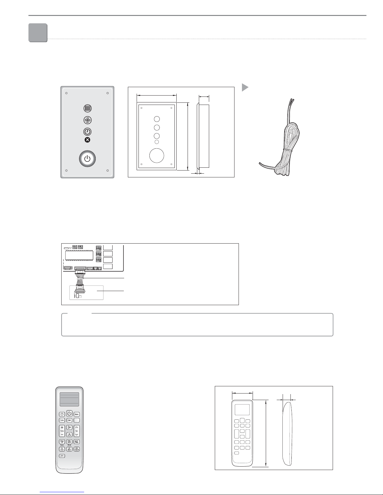
MRK-A10N
1) Features .....................10
2) Wiring.......................10
Receiver & display unit
1
1. MIM-N01
1) Features .....................44
2) Product specification ...........44
3) Description of parts ............45
4) Connection diagram............46
5) Connection...................47
5) Display ......................48
Interface module
2
MR-DH00
1) Features .....................10
2) Description of parts ............11
3) Additional function .............12
Wireless remote controller
4
MWR-VH12N
1) Features .....................35
2) Product specification ...........35
3) Description of parts ............36
4) Option function................37
5) Display ......................40
6) Connection diagram............41
ERV wired remote controller
3
MCM-A202DN
1) Features .....................55
2) Product specification ...........55
3) Description of parts ............56
4) Optional function ..............57
5) Connection diagram............58
6) Display ......................61
OnOff controller
2
MIM-N10
1) Features .....................49
2) Product specification ...........49
3) Description of parts ............51
4) Connection diagram............52
5) Connection...................53
6) Checking the operation .........54
ERV interface module
4
MCM-A300N
1) Features .....................62
2) Product specification ...........62
3) Description of parts ............63
4) Connection diagram............64
5) Connection...................65
6) Main function . . . . . . . . . . . . . . . . . 67
Touch centralized controller
2. MWR-SH00N
1) Features .....................27
2) Product specification ...........27
3) Description of parts ............28
4) Optional function ..............30
5) Display ......................32
6) Communication diagram ........33
3
1. MWR-WE10N
1) Features .....................13
2) Product specification ...........13
3) Description of parts ............14
4) Optional function ..............16
5) Display ......................23
6) Communication diagram ........25
Wired remote controller