zipwake S Series User manual

TROUBLE SHOOTING
GUIDE

TROUBEL SHOOTING GUIDE
DYNAMIC TRIM CONTROL SYSTEM SERIES S
Release: R1A, April 2019
Language: English
Copyright © 2019 Zipwake AB, Sweden. All rights reserved.
www.zipwake.com

GENERAL INFORMATION
•Zipwake Series S Dynamic Trim Control System consists of sealed units which in case of failure shall be
replaced as complete units. Units shall never be opened (warranty void) and only the failing component
shall be returned under the warranty program. Consequently, trouble shooting is essentially about
isolating failing components for replacement.
• Always ensure the system is updated with the latest software. Visit www.zipwake.com to download the
latest software.
• The Control Panel (CP-S) and the Servo unit (SU-S) can report error codes. The CP-S and SU-S have
their individual sets of error codes (bit encoded). The Distribution Unit (DU-S) do not generate any
error codes.
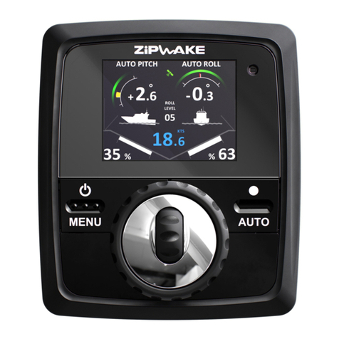
• Presence of system error is indicated in the CP-S
display by a flashing red info–symbol in
combination with a red cross in case of SU-S
error code. In addition, a system error message
flashes for about 3 seconds.
• An error code is read from the CP-S menu,
MENU – System Information – <Select a unit> – Error message
• Multiple errors give an error code corresponding
to the sum of the individual error codes. As an
example, E1536 indicates presence of the two
error codes E512 and E1024. Each error message
text is listed in the CP-S menu.
For more information, refer to Operator’s Manual and Installation Guide available on www.zipwake.com
E512 + E1024 = Error code E1536
3
FOR INTERNAL USE ONLY

CP-S ERROR CODES
4
Series S Control Panel (CP-S)
Blt Description Error message displayed Corrective actions Error code is cleared when...
code on control panel
1Low voltage detect Supply voltage too low • Check battery supply voltage (>12V). ...supply voltage goes above 9V.
• Check the power cable connection to the battery.
2High voltage detect Supply voltage too high • Check the distribution unit power cable. ...supply voltage goes below 32V.
• Check battery supply voltage (12-32V).
4Rotary encoder failure Button/wheel failure • Check if any buttons or wheels are stuck. ...power turned on (main switch toggle).
• Use fresh water to spray and remove any dirt on the control panel front.
8Accelerometer failure Acc/gyro error • Turn off the sustem for 10 minutes, then restart. ...power turned on (main switch toggle).
16 Gyro failure Acc/gyro error • Turn off the sustem for 10 minutes, then restart. ...power turned on (main switch toggle).
32 High circuitboard temp Panel temp. too high • Check if the panel is mounted close to any heat source. ...circuitboard temperature goes below 75°C.
• Try mounting the panel in another (cooler) location.
64 GPS error No GPS signal • Check GPS source and GPS status on the Select GPS source menu page (norm. set to Auto). ...GPS signal is acquired (received).
• If an external GPS or NMEA 2000 GPS is installed, check the cables for damage.
• Check the NMEA 2000 GPS source is turned on.
• Clean and reattach the control panel connectors.
128 Software exception error Program error • Restart the system. ...power turned on (main switch toggle).
• Visit www.zipwake.com for upgrades resolving the issue.
256 <not used>
512 Too few interceptors Interceptor not connected • Check the servo cables for damage. ...more than one servo unit detected (connected).
• Clean and reattach the connectors on the distribution unit. ...a single interceptor is detected (connected) at PORT 3.
• Ensure a single interceptor installation is connected to distribution unit PORT 3.
1024 CAN-bus error Communication error • Check the system cables for damage. ...I-BUS communication is restored.
- Clean and reattach the connectors on the distribution unit and control panels.
• Identify failing component.
- Disconnect all interceptors and flybridge control panels.
- Reconnect units one-by-one to identify which unit triggers error.
Note: connect the interceptor one-by-one to DU at PORT 3 to avoid triggering error code E512
- Replace failing unit.

SU-S ERROR CODES
5
Blt Description Error message displayed Corrective actions Error code is cleared when...
code on control panel
1High motor temperature Motor temperature high • Turn off the system for 10 minutes, then restart. ...motor temp. goes below 81°C.
2Motor drive failure Motor HALL sensor failure • Turn off the system for 10 minutes, then restart. ...power turned on (main switch toggle).
- HALL sensors
4Motor drive failure Motor drive failure • Turn off the system for 10 minutes, then restart. ...power turned on (main switch toggle).
- Phases
8Low voltage detected Supply voltage too low • Check battery supply voltage (>12V). ...supply voltage goes above 8V.
• Check the power cable connection to the battery.
• Check the distribution unit power cable.
16 Interceptor stroke too small Interceptor stroke too small • Turn off the sustem for 10 minutes, then restart. ...system is restarted (power button).
32 Interceptor stroke too big Interceptor stroke too big • Restart the system. ....system is restarted (power button).
• Remove the interceptor front and check that the blades are moving correctly.
Remove any growth, dirt or paint.
• Reinstall the front, run the interceptor and check that the blades are moving correctly
(run Interceptor Check).
64 Electronics failure Electronics failure • Restart the system. ...power turned on (main switch toggle).
• Visit www.zipwake.com for upgrades resolving the issue.
128 Emergency stop Overload, interceptor stuck • Check that the blades are moving correctly (run Interceptor Check). ....system is restarted (power button).
• Check for excessive growth, dirt, paint or sealent on the interceptor and between the moving
components.
• Remove the interceptor front and check that the blades are moving correctly.
• Verify no components are missing (screws, seal, strip, rollers, slide blocks).
• Verify the back plate is flat within tolerance according to installation guide.
• Reinstall the front (tighten with designated torque), run the interceptor and check that the
blades are moving correctly (run Interceptor Check).
• Verify that the system is not connected to power supply via automatic (thermal/magnetic) fuse.
256 High voltage detected Supply voltage too high • Check battery supply voltage (12-32V). ...supply voltage goes below 32V.
512 High circuitboard temp Motor driv temp. too high • Turn off the system for 10 minutes, then restart. ...circuitboard temp. goes below 64°C.
1024 Motor over current Motor over current • Turn off the system for 10 minutes, then restart. ...system is restarted (power button).
Series S Servo Unit (SU-S)

SU-S: E032 – INTERCEPTOR STROKE TOO BIG
POSSIBLE CAUSES AND CORRECTIVE ACTIONS
•,QVXI²FLHQWSRZHUVXSSO\
NOTE: E032 due to poor power supply will effect all servo units!
1. Check battery and/or charger condition to ensure the supply delivers the expected power.
2. Check power supply connections and verify that all cables have the correct dimensions
(wire diameters shall be 12 AWG or larger).
3. Verify power supply is not connected via automatic thermal/magnetic fuses.
4. Connect Zipwake directly to a new separate battery to completely rule out the power supply as
cause of failure.
•(OHFWULFDOIDLOXUHRI686
1. Rule out power supply issue (see previous check-list).
2. Check if the SU-S that reports error operates (makes any movement) at system turn on.
3. Replace SU-S if confirmed it is not operating.
•6HUYRXQLW¬VVFUHZVKDIWKDVEURNHQ
1. Restart the system and listen for the SU-S operating at system turn on (or when powered up as
connected to the DU-S). A screw shaft failure is suspected if the SU-S runs for a longer period
(a couple of seconds) than normal, followed by the error code E032.
2. Disconnect servo unit from the interceptor back plate and check the movement of screw shaft and
nut when motor is running. If the shaft/nut is not moving or can be visually confirmed to be
broken, replace the servo unit.
•The electronics sense the electrical motor operates out of range,
primarily occurs in connection to system startup.
ERROR CODE TRIGGER
6

SU-S: E128 – OVERLOAD, INTERCEPTOR STUCK
POSSIBLE CAUSES AND CORRECTIVE ACTIONS
•,QVXI²FLHQWSRZHUVXSSO\WKDWGRHVQRWVXSSO\HQRXJKSRZHUGXULQJWHPSRUDU\SHDNV
LQLQWHUFHSWRUORDG
1. Measure voltage and verify no significant temporary voltage drops occur during operation.
2. Check power supply connections and verify that all cables have the correct dimensions.
Wire diameters shall be 12 AWG or larger.
3. Verify power supply is not connected via automatic thermal/magnetic fuses.
4. Connect Zipwake directly to a new separate battery to completely rule out the power supply as
cause of failure.
•2EVWUXFWHGLQWHUFHSWRUEODGHPRYHPHQW
1. Check that the blades are moving correctly – run Interceptor Check. Compare with the results
obtained for the Interceptor Check executed in connection to the installation. In case of any
indication the blades are obstructed (Interceptor Check readout not in the green range), check for
excessive marine growth, dirt, paint or sealant on interceptor’s moving parts.
2. Remove the Interceptor front and verify that the blade and backplate’s connecting rod are moving
freely (shall be easy to move by hand).
3. Verify the servo is working properly and runs freely - run Interceptor Check with the front
removed, and also with the SU-S removed from the backplate. The readings should be distinctly
lower than the result with the front and blade mounted.
4. Verify no components are missing (screws, seal).
5. Verify the back plate is mounted flat within tolerance according to installation guide,
see illustration below.
6. Correct (clean or replace) any idientified source that obstruct the interceptor blade movement.
•The electronics sense too high load to the SU-S electrical motor.
Connecting rod shall move freely. Transom flatness tolerance.
ERROR CODE TRIGGER
7
Max 2 mm (0.08”)
between parallel
planes

•6FUHZVKDIWQXWRI686LVQRW²WWHGFRUUHFWO\WRWKHLQWHUFHSWRUEDFNSODWH¬VFRQQHFWLQJURG
1. Remove the SU-S from the backplate and verify the screw shaft nut and connecting rod are fitted
correctly when remounted.
•(OHFWURQLFIDLOXUH
1. Remove the SU-S from the backplate and verify nothing is mechanically preventing movement
(see previous ”Obstructed interceptor blade movement”).
2. Examine the behavior when powering up the SU-S. Replace the SU-S if the motor do not operate
at all (there should be more than just a ‘click’ sound – compare with a functional SU-S).
•6FUHZVKDIWQXWVWXFNLQRXWHUSRVLWLRQFDQRFFXULILQQHUSRVLWLRQFDQQRWEHUHDFKHG
GXULQJ686VWDUWXSVHTXHQFH
1. Remove any obstacles (growth, dirt, mud, paint etc.) that prevents the interceptor blade to fully
retract.
2. Check and verify the SU-S is mounted with the screw shaft nut and the backplate connecting rod
fitted correctly (see illustration below).
3. If the screw shaft nut do not retract from the outmost position when the SU-S is removed from
the backplate, then free the screw shaft nut by using a torx screwdriver at the shaft end to gently
rotate the screw shaft just enough to free the nut from the end stop. Connect the SU-S to the
distribution unit and let the motor retract the screw shaft nut to the inner position.
8
1
Instructions of mounting the SU-S to the backplate. Ensure screw shaft nut is
fitted correctly to the backplate’s connecting rod.
Servo unit:
2 Nm (1.5 Ib-ft)
1
1
2
NOTE!
(x3)
T25 (PT 5.0x18)

CP-S: E512 – INTERCEPTOR NOT CONNECTED
POSSIBLE CAUSES AND CORRECTIVE ACTIONS
•1RLQWHUFHSWRULVFRQQHFWHGWRWKH'86
1. Connect at least one interceptor to complete the system installation.
•$QLQVWDOODWLRQZLWKRGGQXPEHURILQWHUFHSWRUVDUHQRWFRUUHFWO\FRQQHFWHGWRWKH'86
1. Connect the interceptor pairs to the DU-S starting at PORT/STBD 1.
2. Connect the single (centerline mounted) interceptor to the PORT3 connector at the DU-S
(see illustration below).
•$FRQQHFWHGVHUYRXQLWLVQRWLGHQWL²HGE\WKHV\VWHP
1. Check that the system units listed in the CP-S under ’System Information’ agrees with the
actually connected units.
2. Check cable and connectors for dirt or damage. Try connecting SU-S to a different connector of
the DU-S. Replace any damaged cables/units.
3. Verify function of the servo units individually by disconnect all and reconnecting them one-by-one
to DU-S at the PORT3 connector.
4. Replace any failing servo unit that does not get recognized by the system or otherwise does not
operate properly.
•The system cannot identify interceptor or interceptor pairs.
ERROR CODE TRIGGER
9
Installations with a centerline interceptor connected to DU-S PORT 3.
Port interceptor 1 not identified by the system.

CP-S: E1024 – COMMUNICATION ERROR
POSSIBLE CAUSES AND CORRECTIVE ACTIONS
•'DPDJHGFDEOHWR686RUFDEOHFRQQHFWLQJ'86DQG&36RUEHWZHHQH[WUD&36
1. Examine the cables and connectors for dirt or damages.
2. Replace any damaged or bad cable/units.
•7KHV\VWHPLQFOXGHVRQO\RQH'86DQGRQH&36LHWKHUHLVQRRWKHUXQLWFRQQHFWHG
IRUWKH&36WRFRPPXQLFDWHZLWK
1. The error is cleared once at least one additional unit, CP-S or SU-S is connected.
•6\VWHPXQLWIDLOXUHWKDWFRUUXSWVWKHFRPPXQLFDWLRQOLQN
Identify the failing unit.
1. Disconnect all units in the system except one CP-S connected to the DU-S on the I-BUS OUT
connection.
2. Connect the SU-S units one-by-one to the DU-S at PORT3 connection and identify which SU-S
that triggers the error code when connected. Extra CP-S units are tested by connecting to the
main CP-S at the I-BUS OUT connection.
3. Replace any unit identified to trigger error code and verify full functionality with the complete
system connected.
•No or unreliable communication between system units.
NOTE: E1024 is frequently accompanied with error code E512, resulting in an
error code E1536.
ERROR CODE TRIGGER
10
Presence of error message for a specific unit identifies the failing system unit.
SU-S connected
one-by-one to
DU-S at PORT 3.

REINSTALLATION OF SU-S AND INTERCEPTOR FRONT
INSTALLING THE SERVO UNIT AND INTERCEPTOR FRONT
•Verify the connecting rod moves freely in the backplate.
•Verify the screw shaft nut is correctly fitted to the connecting rod in the backplate
when mounting the servo unit. Tighten screws with designated torque (2 Nm).
•Verify the interceptor blades are moving easily (blades shall be easy to move by hand.)
•Reinstall the front and tighten the screws with designated torque (5 Nm).
•Run the Interceptor Check and verify that the blades are moving freely within tolerance
range (all the readings of Interceptor Check are in green range). Document and archive the
results for later reference.
11
Instructions of mounting the SU-S and the front to the backplate. Ensure screw shaft nut is fitted correctly to the backplate’s
connecting rod. Tighten the screws with designated torque (2 Nm and 5 Nm, respectively).
Starting Interceptor Check from the Control Panel menu.
Servo unit:
2 Nm (1.5 Ib-ft)
1
1
2
NOTE!
(x3)
T25 (PT 5.0x18)
5 Nm
(3.7 lb-ft)
300 S:
450 S:
600 S:
750 S:
x6
x10
x14
x18
Interceptor front: T30 (PT 6.0x48)

Other manuals for S Series
3
Table of contents
Other zipwake Control System manuals
Popular Control System manuals by other brands

Sorotec
Sorotec MINI Control Assembly instruction

Waterway
Waterway NEO 2100 instruction manual

Data Aire
Data Aire dap4 touch user manual

Anticimex
Anticimex Smart Connect Mini user manual

Exhausto
Exhausto EFC 25 Installation & operating instructions

LIFE home integration
LIFE home integration RG1R DL S SUPRA MB 230 Vac Instruction and Advertising for use and Maintenance