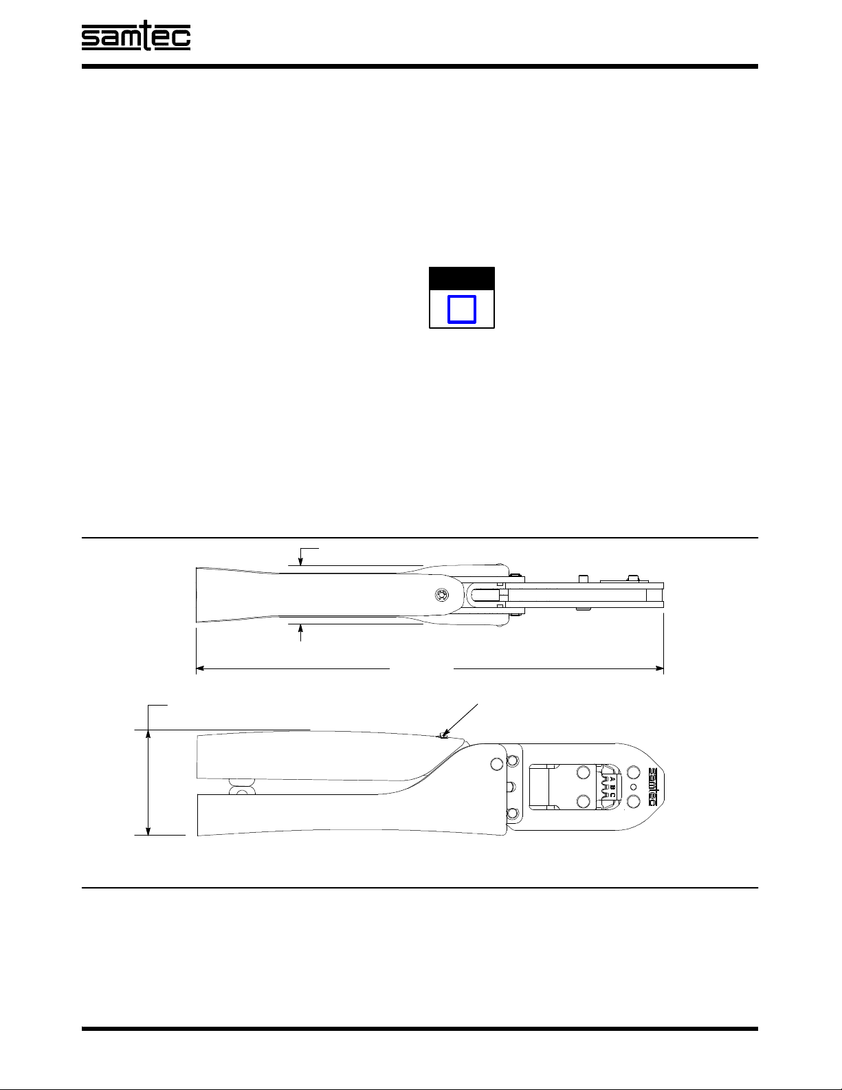
Straight Action Hand Tool CAT- HT- 203- 2832- 11 STS- M- 203- 2832- 11- A
2of 3 SAMTEC
All Rights Reserved.
CUSTOMER SERVICE 1--800--SAMTEC9
CONTACT
NUMBER
WIRE SIZE
mm2[AWG]
INSULATION
DIAMETER
STRIP
LENGTH
TOOL CRIMP
SYMBOL
CRIMP
HEIGHT
APPLICATION
SPECIFICATION
0.05--0.06 [30] 0.74--0.89
[.029--.035]
2.28--2.54
[.092--.098] B0.41 +0.025
[.016 +.001]
03
0.08--0.09 [28] 0.81--0.97
[.032--.038]
2.28--2.54
[.092--.098] C0.46 +0.025
[.018 +.001]
--
--006
Figure 2
9. If a terminal becomes jammed in the crimp nest,
the tool jaws can be opened using the “emergency
ratchet release button,” found on the moving
handle lever.
Damaged terminals should not be used. If a
damaged terminal is evident, it should be cut
from the wire and replaced with a new one.
4. MAINTENANCE AND INSPECTION PROCEDURE
It is recommended that a maintenance and inspection
program be performed periodically to ensure
dependable and uniform terminations. Frequency of
inspection depends on:
SThe care, amount of use, and handling of the
hand tool
SThe presence of abnormal amounts of dust and
dirt
SYour own established standards
The hand tool is inspected before being shipped;
however, it is recommended that the tool be inspected
immediately upon its arrival at your facility to ensure
that the tool has not been damaged during shipment.
4.1. Daily Maintenance
1. Remove dust, moisture, and other contaminants
with a clean brush, or a soft, lint--free cloth. Do
NOT use objects that could damage the tool.
2. Make certain that the retaining pins are in place
and that they are secured with retaining rings.
3. All pins, pivot points, and bearing surfaces
should be protected with a thin coat of any good
SAE 20 oil. Do not oil excessively.
4. When the tool is not in use, keep handles closed
to prevent objects from becoming lodged in the
crimping jaws. Store the tool in a clean, dry area.
4.2. Lubrication
Lubricate all pins, pivot points, and bearing surfaces
with SAE 20 oil as follows:
STools used in daily production -- lubricate daily
STools used daily (occasional) -- lubricate weekly
STools used weekly -- lubricate monthly
Wipe excess oil from tool, particularly from crimping
area. Oil transferred from the crimping area onto
certain terminations may affect the electrical
characteristics of an application.
4.3. Periodic Inspection
1. Hand tool may be immersed (handles partially
closed) in a reliable commercial degreasing
compound (suitable for plastics) to remove
accumulated dirt, grease and foreign matter.
2. Close tool handles until ratchet releases and
then allow them to open freely. If they do not open
quickly and fully, the spring is defective and must
be replaced.
3. Inspect head assembly for worn, cracked, or
broken jaws. If damage is evident, return it for
evaluation and repair.
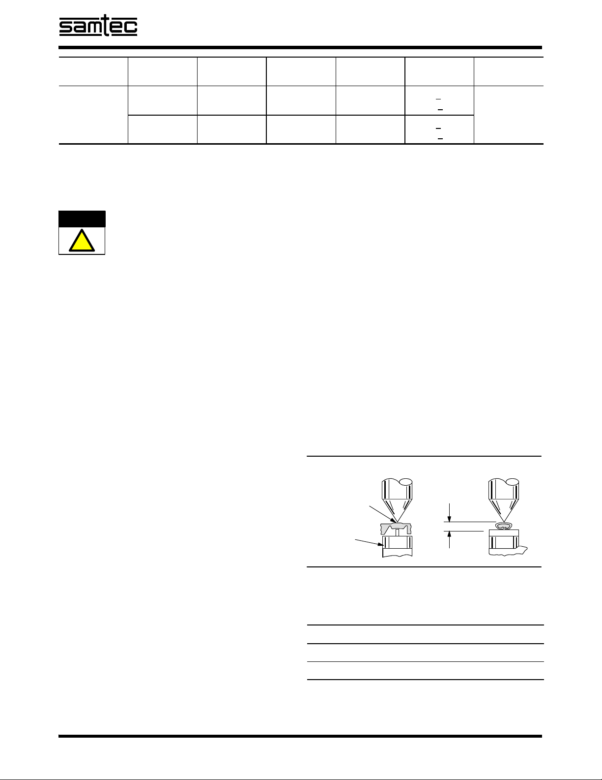
4.4. Crimp Height Inspection
This inspection requires the use of micrometer with a
modified anvil as shown in Figure 3.
Figure 3
Modified
Anvil
Position Point
On Center of
Wire Barrel
Opposite Seam
Wire Barrel
Crimp Height
A recommended Crimp Height Comparator is
RS--1019--5LP, which can be purchased from:
Manufacturer Telephone
Shearer Industrial Supply Co 717--767--7575
VALCO 610--691--3205
CAUTION
!