Sandberg 130-80 User manual

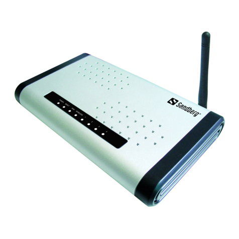
Sandberg Wireless
N300 Router
[Item no. 130-80] Rev. 22.10.07
ENGLISHDANSKNORSKSVENSKASUOMI

2
Figure 1 – Example of network setup
Introduction
Sandberg Wireless N300 Router allows you to share a broadband connection and local area
network connection using both wireless and wired connections. The Sandberg Wireless N300
Router is easy to configure thanks to its user-friendly web interface. Its features include a range
of security settings that you can configure to prevent uninvited guests.
The Sandberg Wireless N300 Router is based on 802.11n technology, which means that the router
is significantly faster and has a longer range than earlier wireless network standards. 802.11n is
backwards compatible with earlier wireless network standards such as 802.11g and 802.11b, so
you can also easily use older wireless equipment with your new N300 router.
NB: The router works with ADSL, xDSL, FWA and cable modem connections that support Ethernet,
PPPoE, L2TP or PPTP (using RJ45 connectors). Your Internet service provider will be able to tell
you whether your internet connection uses one of these four standards, enabling you to share
the connection.
1 Installing the router
1.1 Role of the router on the network
A router acts as a connection point between two networks. A router is generally used to connect
a local area network with multiple computers to the network of an Internet service provider. In
other words, a router allows several computers to share an Internet connection. The Sandberg
Wireless G54 Router is wireless, meaning that computers with wireless network cards can connect
to it without the use of cables.
Figure 1 shows an example of a typical network setup, with two computers sharing an Internet
connection.
Internet
DSL or
cable modem Router
Computer 1
Computer 2
ENGLISH

3
Figure 2 – External and internal IP addresses
As the router’s role is to create a bridge between two networks, it has one IP address for each
network. One IP address represents the router on the Internet and is called the external IP address,
and the other represents the router on the local area network and is called the internal IP address.
Each of the computers on the local area network also has its own IP address. This can be allocated
automatically by the router (using the router’s DHCP function) or it can be specifi ed manually on
each computer.
Figure 2 shows a typical network setup, and the IP addresses that form part of that setup.
172.64.102.85 is the router’s external IP address. When communicating with a computer over the
Internet, it will be this address that the computer ‘sees’, regardless of which computer on the local
area network is being used. The external IP address can either be dynamic or fi xed, depending
on the type of subscription set up with the Internet service provider. A dynamic IP address is one
that is allocated by the Internet service provider, but it is not necessarily the same address all
the time. A fi xed IP address always remains the same.
192.168.2.1 is the router’s internal IP address. This is the address of the router on the local area
network, the one that all the computers on the network connect to in order to access the Internet.
192.168.2.100 is the IP address of a computer on the network. This can either be defi ned in
Windows or be automatically allocated by the router.
192.168.2.101 is the IP address of a computer on the network. This can either be defi ned in
Windows or be automatically allocated by the router.
Computer 1
Computer 2
External
172.64.102.85
192.168.2.1
192.168.2.100
192.168.2.101
ENGLISH

4
1.2.1 Lamp indications
1.2 Connecting the router
Figure 3 – Router ports
The router can function both as a router and an access point. The connection mode used with
the router depends on how it is intended to function on the network.
• Router – Used if the Internet connection is to be shared between multiple computers, either
wirelessly, with cables, or both.
• Access Point – Used if the Internet connection is already shared between multiple computers,
e.g. via a router, and wireless access to the Internet is required. In this case, the role of the router
is to provide wireless access to the existing router.
1. Connect the electrical plug to a mains socket and the small round connector on the power lead
to the 12VDC socket on the router. Check that the “Power” lamp lights up.
• If you will be using the router function, connect the router’s WAN port to your existing ADSL/
broadband connection using a network cable.
• If you will be using the access point function, connect a network cable from the existing
network (typically the existing router) to port 1, 2, 3 or 4 on the router.
2. The fixed antennae can be folded upwards to increase the signal strength.
3. Connect up to four computers to the ports marked 1 to 4 on the router. If you will only be
connecting wirelessly, skip this step.
4. Start the connected computers.
1.2.2 Positioning and installation of the router
To ensure the best possible wireless signal conditions, the router should be placed centrally in
relation to the devices connecting wirelessly to it.
The package includes an installation kit containing four rubber feet, two screws and two rawlplugs.
The rubber feet can be stuck to the base of the router to stand it on a fl at surface.
If you wish to wall-mount the router, drill two holes in the wall 14 centimetres (5.51 inches) apart.
At the back of this manual there is a drill template that you can cut out and use to ensure the
holes are the correct distance apart. On the back of the router there are two sets of brackets,
allowing it to be mounted with the connectors facing up or down.
LED
PWR
WLAN
WAN - 10/100M
WAN - LNK/ACT
LAN - 10/100M
LAN – LNK/ACT
Colour
Green
Green
Green
Green
Green
Green
Status
On
On
Flashing
Off
On
Flashing
Off
On
Flashing
Off
On
Off
On
Flashing
Off
Status
The router is on.
Wireless connection is active.
Wireless connection transmitting data.
Wireless connection is inactive.
100 Mbit/s connection active.
WAN port transmitting data.
10 Mbit/s connection active.
WAN port connected.
WAN port transmitting data.
WAN port disconnected.
100 Mbit/s connection active.
10 Mbit/s connection active.
LAN port connected.
LAN port transmitting data.
LAN port disconnected.
ENGLISH

5
2 Configuring the router
2.1 Setting up the router
NB: If you will be using the router as an access point only, the following steps can be skipped.
However, the router’s wireless security function should be enabled. (See section .)
To access the router configuration, you need to set up the computers on the same network as
the router. In other words, the computers must be set up to have their IP addresses automatically
allocated by the router. The computer’s network card is usually already set to do this. But if you
have any problems accessing the router configuration, this setting should be checked under the
network card’s settings in the control panel.
If you will be using the router wirelessly, the computer must be connected to the router’s wireless
network before the following steps can be carried out. See the documentation that came with
the computer’s wireless network card for information on how to connect to a wireless network.
1. Start your Internet browser (e.g. Internet Explorer®).
2. Type http://192.168.2.1 in the browser’s address bar and press Enter.
3. In the Username fi eld, type admin.
4. In the Password fi eld, type 1234. Click [OK].
5. Click the [Quick Setup] button.
Figure 4 – Router confi guration utility
The default router confi guration wizard will now start.
2.1.1 Time Zone
1. Select the appropriate time zone.
2. The Time Server Address fi eld allows you to enter the IP address of a time server to set the
router clock automatically. The fi eld contains a default value, but can be changed if you wish
to use a different time server.
3. The Daylight Savings fi eld indicates whether the router will switch automatically between
summer time and winter time. Check the box Enable Function, and enter the dates for changing
to summer time or winter time.
4. Click [Next].
ENGLISH

6
2.1.2 Broadband Type
Here you can enter the type of connection used by the router. Contact your Internet service
provider if you are unsure which type of Internet connection you have.
• Select Cable modem if you have a cable modem or other type of Internet connection without
a fi xed IP address.
o Host name: Can be set to any name unless specifi ed by your Internet service provider.
The MAC address is automatically set to the MAC address of your cable modem. This should
not be changed unless specifi ed by your Internet service provider.
o Clone MAC address: This function is usually not required for default setup. This button can
be used to specify the MAC address of the computer’s network card as the actual MAC address
of the router.
o When your changes are complete, click [OK]. The router will then confi rm the changes. Click
[OK].
o Close the window by clicking the cross in the top right corner.
• Select Fixed-IP xDSL if you have an xDSL or Ethernet connection with a fi xed IP address.
o IP address assigned by your service provider: Enter the IP address assigned by your Internet
service provider.
o Subnet mask: Enter the subnet mask assigned by your Internet service provider.
o DNS address: Enter the DNS addresses assigned by your Internet service provider.
o Service provider gateway address: Enter the gateway address assigned by your Internet
service provider.
o When your changes are complete, click [OK]. The router will then confi rm the changes. Click
[OK].
o Close the window by clicking the cross in the top right corner.
• Select Dial-up xDSL (PPPoE) if you have an xDSL/FWA connection that uses PPPoE.
o User name: Enter the username assigned by your Internet service provider.
o Password: Enter the password assigned by your Internet service provider.
o Service name: Enter the service name assigned by your Internet service provider. If you have
not been assigned a service name by your Internet service provider, this fi eld can be left
blank.
o MTU (1400-1492): The router will propose 1492. You can accept this unless your Internet
service provider recommends a different value.
o Connection type: There are three options to choose from:
Continuous – the router maintains a permanent connection to your Internet service provider.
Connect on demand – the router only connects when necessary and disconnects itself after
a set period of time (see Idle time).
Manual – you activate the connection through the router yourself when you need it.
o Idle time: Specifi es the period of time after which the router will disconnect when it is not
in use. This function is only used if the Connection type is set to Connect on demand.
o When your changes are complete, click [OK]. The router will then confi rm the changes. Click
[OK].
o Close the window by clicking the cross in the top right corner.
• Select PPTP xDSL if you have a connection of this type.
o WAN Interface Settings: Set the router to obtain an IP address automatically, or enter the IP
address, subnet mask and gateway if these have been assigned to you by your Internet service
provider.
o PPTP Settings: Enter the information assigned by your Internet service provider in the
appropriate fields.
o When your changes are complete, click [OK]. The router will then confirm the changes. Click
[Apply].
o Close the window by clicking on the cross in the top right corner.
ENGLISH

7
• Select L2TP xDSL if you have a connection of this type.
o WAN Interface Settings: Set the router to obtain an IP address automatically, or enter the IP
address, subnet mask and gateway if these have been assigned to you by your Internet service
provider.
o L2TP Settings: Enter the information assigned by your Internet service provider in the appropriate
fields.
o When your changes are complete, click [OK]. The router will then confirm the changes. Click
[Apply].
o Close the window by clicking on the cross in the top right corner.
The default router configuration is now complete. However, before using the router, you should
secure it against unauthorised wireless access. The following section contains information on
how to do this.
2.2 Securing a wireless network
If you are using the router’s wireless functionality, the network must be secured against
unauthorised access by enabling one of the router’s built-in security features. This protects
authorised network users against unauthorised access from the outside.
The router can use one of the following security features:
• WEP
• WPA pre-shared key
• WPA RADIUS
All computers that connect wirelessly to the router must use the same type of security as the
router. It is therefore important to select a security method supported by all the network cards
on the network. For more information on this, see the user guide for the individual network cards
on the network.
For additional security, the MAC Address Filtering function can be used. See section 2.3.4 for
information on this.
Configuration of the various security features is described in the following sections.
2.2.1 Configuring WEP
1. Click [General Setup].
2. Click [Wireless], then [Security Settings].
3. Under Encryption, select WEP.
4. Under Key Length, select the encryption strength. You can select either 64-bit or 128-bit.
For greatest security, 128-bit is recommended.
5. Under Key Format, select the format for entering security codes. You can select either HEX
(digits and/or letters from A to F) or ASCII (letters and/or digits).
6. Under Default TX Key, select the security code to use as default.
7. In the fi elds Encryption Key 1-4, enter up to four security codes. If you enter multiple codes,
computers can access the network wirelessly by entering any one of them. The codes must
comply with the format given in Key Length and Key Format. Both upper and lower case letters
can be used.
64-bit HEX – 10 digits and/or letters from A to F
128-bit HEX – 26 digits and/or letters from A to F
64-bit ASCII – 5 letters and/or digits
128-bit ASCII – 13 letters and/or digits
8. Click [Apply].
9. Click [Continue] to change more settings or [Apply] to restart the router for the new settings
to take effect.
ENGLISH

8
2.2.2 Configuring WPA pre-shared key
1. Click [General Setup].
2. Click [Wireless], then [Security Settings].
3. Under Encryption, select WPA pre-shared key.
4. Under WPA Unicast Cipher Suite, select the type of encryption to use. You can select WPA(TKIP),
WPA2(AES) or WPA2 Mixed. Note that all devices connecting to the network must support the
encryption type.
5. Click [Apply].
6. Click [Continue] to change more settings or [Apply] to restart the router for the new settings
to take effect.
2.2.3 WPA RADIUS
This type of security is for advanced users and requires a separate RADIUS server. WPA RADIUS
is typically used in larger corporate networks, and is not recommended for private use. Documentation
on confi guring the router for WPA RADIUS can be found in the English manual on the CD
provided.
2.2.4 Configuring MAC Address Filtering
All network devices have a unique code called the MAC address.
Mac Address Filtering is an extra security feature that ensures that only network devices with
MAC addresses approved by the router can connect to the wireless network.
1. Click [General Setup].
2. Click [Wireless], then [Access Control].
3. In the MAC address fi eld, enter a MAC address.
4. If necessary, enter a comment for the MAC address in the Comment fi eld.
5. Click [Add] to add the MAC address to the list of approved addresses.
How to discover the MAC address of a wireless network card
Windows®Vista
1. Click Start. Type “cmd” in the Start searching field and press Enter.
2. Type “ipconfig /all”, then press Enter.
3. Locate the line with “Description…” followed by the name of the wireless network card.
The value indicated for Physical address is the network card’s MAC address.
Windows®XP
1. Click Start, then Control Panel, then Network and Internet Connections, then Network
Connections.
2. Double-click the icon for the wireless network connection, click the Support tab and then
click Details...
3. The value indicated for Physical address is the network card’s MAC address.
Windows®2000
1. Click Start, then Run. Type “cmd” in the field and press Enter.
2. Type “ipconfig /all”, then press Enter.
3. Locate the line with “Description…” followed by the name of the wireless network card.
The value indicated for Physical address is the network card’s MAC address.
ENGLISH

3 Advanced setup
Advanced setup enables you to defi ne specifi c settings for your network’s security policy, data
traffi c, etc. This requires specialised knowledge, including network technologies and security
policies, and is only recommended for users with experience in these areas. These settings are
not usually required for standard setup.
1. Start your Internet browser (e.g. Internet Explorer®).
2. Enter “http://192.168.2.1” in the browser’s address bar and press Enter.
3. In the Username fi eld, type “admin”.
4. In the Password fi eld, type “1234”.
5. If you want this to be remembered next time you log on, check the box Remember password.
Click [OK].
6. Click the [General Setup] button.
3.1 System
The System menu contains settings for the time zone, password and remote access to the router.
3.1.1 Time Zone
• Select the time zone in the Set Time Zone menu.
• Enter the IP address of a time server in the Time Server Address fi eld. The fi eld contains
a default value, but can be changed if you wish to use a different time server.
• Check the box next to Enable Function and set the start and end date for summer time in
the Daylight Savings fi eld.
• Click [Apply] to confi rm the settings.
3.1.2 Password Settings
To change the password for access to the router, follow the steps below.
• Enter the current password in the Current Password fi eld.
• Enter a new password in the New Password and Confi rmed Password fi elds.
• Click [Apply] to confi rm the settings.
3.1.3 Remote Management
Settings for remote access to the router confi guration utility. Remote access allows the router
to be configured from a computer via the Internet.
NB: If you enable remote access, it is essential that you change the default password for router
access to a password of your choosing. See section 3.1.2.
• Check the box next to Enabled to enable remote access.
• In the Host Address fi eld, enter the IP address of the computer on the Internet that will have
remote access to the router confi guration utility.
• Enter IP address 0.0.0.0 to give all computers remote access.
• Click [Apply] to confi rm the settings.
3.2 WAN
Settings for manual confi guration of the connection type. The settings are the same as those
confi gured in Quick Setup. See section 2.2 (subsection WAN Type) for information on the various
settings.
3.3 LAN
For setting the router’s IP address and confi guring its DHCP server.
9
ENGLISH

10
3.3.1 LAN IP
• Enter the desired IP address for the router in the IP Address fi eld.
• Enter the subnet mask in the IP Subnet Mask fi eld.
• Click [Apply] to confi rm the settings.
3.3.2 DHCP Server
• In the Start IP fi eld, enter the fi rst IP address in the range that the DHCP server can allocate.
• In the End IP fi eld, enter the last IP address in the range that the DHCP server can allocate.
• If necessary, the router’s DHCP server can be disabled by selecting Disabled in the DHCP Server
field.
• Click [Apply] to confirm the settings.
3.4 Wireless
Enable or disable wireless access to the router. By default, this function is enabled.
• Select Enable to enable wireless access to the router, or Disable to disable the function.
• Click [Apply] to confi rm.
3.4.1 Basic Settings
• In the ESSID field, enter the name of the wireless network. This is the name that will be shown
when Windows®displays a list of available wireless networks.
• Mode, Band and Channel Number are advanced settings and should only be changed in special
circumstances.
3.4.2 Advanced Settings
This menu contains advanced settings for the wireless network. They require thorough knowledge
of wireless networking technology and do not normally need to be changed. Documentation on
these functions can be found in the English manual on the CD provided.
3.4.3 Security Settings
See section 2.3.
3.4.4 Access Control
See section 2.3.4.
3.4.5 WPS
This function makes it easier to encrypt the wireless network.
1. Select the desired encryption under Security Settings (see section 2.2).
2. Select Enable WPS under WPS.
3. The network will now be registered as a network with WPS support in the network setup for
the connected computers.
4. You can now start to connect the computer to the router (for more information on this, see
the user guide for the individual network cards in the network).
I. PBC: Click Start PBC in the router configuration and then activate the PBC of the computer
you want to connect.
II. PIN: Type the WPS code of the computer you want to connect into the router configuration
(you generally find the code under the computer’s WPS setup) and then click on Start PIN.
Then activate PIN on the computer you want to connect.
5. The router will now automatically create a secure wireless connection to the configured
computers.
NB: The network card of each computer must support WPS for this function to be used.
ENGLISH

3.5 QoS
• Reserve bandwidth for specifi c web applications.
• Limit bandwidth usage for specifi c web applications.
Quality of Service (QoS) is a function that allows the router to prioritise bandwidth usage so that
specifi c services are always guaranteed a certain level. This can be very useful for services such
as IP telephony, to ensure that call quality is not diminished when there is heavy network traffi
c. QoS can also be used to impose a maximum limit on the bandwidth usage of certain applications.
To use Quality of Service, one or more rules must be set up to defi ne the bandwidth requirements
for certain applications.
The router has no direct link to applications on the computer, so the only way to control the
applications’ network traffi c is to confi gure rules regulating traffi c on the network ports used
by the applications. You therefore need to know which network ports are used by an application
before you can set up a Quality of Service rule. The ports an application uses can normally be
found in the application’s written documentation or on its website.
3.5.1 QoS menu
The QoS menu contains a list of rules that have been set up. Every rule on the list has a priority
(Priority). The rule with the highest priority is allocated bandwidth fi rst, and so on down the list.
Network traffi c that is not covered by user-defi ned rules is allocated bandwidth last of all.
NB: If the total bandwidth allocated to user-defi ned rules exceeds the bandwidth the Internet
connection can deliver, no bandwidth will be available for other applications.
• Enable QoS – Enable Quality of Service. Check this box if you wish to use Quality of Service.
Click [Apply] to confi rm.
3.5.2 Adding a QoS rule
1. Click [Add].
2. Enter a name for the rule in the Rule Name field. This could be the name of the application
the rule relates to.
3. Under Bandwidth, the fi rst fi eld allows you to select whether the rule will apply to incoming
traffi c (Download) or outgoing traffi c (Upload). If you need to establish rules for both incoming
and outgoing traffi c, you must set up one rule for each.
4. In the second fi eld, enter the amount of bandwidth you wish to reserve. This must be given
in kilobits per second (kbps).
5. In the third fi eld, indicate whether the bandwidth entered is a guaranteed minimum (Guarantee)
or a maximum limit that cannot be exceeded (Max).
6. In the Local IP Address fi eld, enter the local IP addresses the rule will apply to. Enter a start
address and end address in the fi elds. For example, 192.168.2.1-192.168.2.255 would represent
all the computers on the network 192.168.2.xxx (where “xxx” is a number between 1 and 255)
7. In the Local Port Range fi eld, enter the local network ports the rule should apply to. If the
application only uses a single port, enter it in this fi eld. Otherwise a range of ports can be
specifi ed by using a hyphen. For example: 800-1000, which specifi es all ports between 800
and 1000.
8. In the Remote IP Address field, enter an IP address on the Internet, from which all traffi c will
be subject to the rule. Traffi c not originating from this address will not be affected. It is not
normally necessary to enter a value for this fi eld.
9. In the Remote Port Range field, enter one or more ports, from which all traffi c will be subject
to the rule. Traffi c not originating from these ports and the address entered under Remote IP
Address will not be affected. It is not normally necessary to enter a value for this fi eld.
11
ENGLISH

12
10. Traffi c Type – Choose between a range of predefi ned types of network traffi c. If you select
a type here, you do not need to enter a value for Local Port Range. The options are:
a. None – No traffi c type is selected. Select this if a value has been entered for Local Port
Range.
b. SMTP – Outgoing email.
c. HTTP – World Wide Web.
d. POP3 – Incoming email.
e. FTP – FTP server.
11. Protocol – Select the network protocol the rule applies to. You can select either TCP or UDP.
Information on the protocols used by an application can be found in the application’s
documentation. If an application uses both protocol types, two QoS rules must be set up.
12. Click [Save] to add the rule. Click [OK]. Click [Apply].
3.5.3 Moving a QoS rule
If a rule needs to be allocated higher or lower priority, it can be moved up or down the list.
1. To select a rule, check the box next to it in the Select column.
2. Click [Move Up] to give the rule higher priority or [Move Down] to give it lower priority.
3. Click [Apply].
3.5.4 Deleting a QoS rule
1. To select a rule, check the box next to it in the Select column.
2. Click [Delete Selected].
3. Click [OK] in the two boxes that appear.
4. Click [Apply].
3.5.5 Deleting all QoS rules
1. To select a rule, check the box next to it in the Select column.
2. Click [Delete All].
3. Click [OK] in the two boxes that appear.
4. Click [Apply].
3.6 NAT
NAT (Network Address Translation) is a technology that allows multiple computers on a local
area network to share the same external IP address. The way this works is that the router manages
all the network traffi c originating from the computers on the network and sorts incoming network
traffi c so it is redirected to the right computer. However, this may cause a problem for network
traffi c that is not initiated at the request of a computer on the local area network.
A typical scenario is when a computer on the local area network is set up as a server. In this case,
a computer on the Internet would connect to the router’s external IP address. However, this network
request does not indicate which computer on the local area network it is addressed to, and the
router therefore has no means of knowing where to forward it. This is solved by setting up the
router’s NAT function so that it forwards incoming network traffi c on certain network ports to a
specifi c IP address on the local area network.
Example: An FTP server is set up on a computer on the network with the IP address 192.168.2.100.
FTP uses network port 21 by default. The router’s NAT function is set up to forward all incoming
traffi c on port 21 to IP address 192.168.2.100.
It may also be necessary to confi gure NAT for applications such as IP telephony, fi le sharing
and online gaming to work properly.
NAT can be confi gured in two modes: Port Forwarding and/or Virtual Server. These are described
in the following sections.
ENGLISH

3.6.1 Port Forwarding
Port Forwarding means setting up rules specifying the type of network traffi c to be redirected
to a particular computer on the local area network.
NB: For Port Forwarding to work as intended, the computer that network traffi c is forwarded to
must be confi gured with a static IP address. See section 3.6.3 for information on this.
1. Click [General Setup]. Click [NAT]. Click [Port Forwarding].
2. Check the box next to Enable Port Forwarding.
3. Enter the IP address of the computer on the local area network to redirect to in the
Private IP field.
4. Specify the type of network traffi c to redirect under Type. Select TCP, UDP or both (Both). The
network traffi c type depends on the type of application used on the computer that traffi c is
forwarded to. If necessary, see the application’s documentation for details on this.
5. Enter the ports from which network traffi c should be forwarded in the Port Range field.
6. If you wish, enter a comment in the Comment fi eld.
7. Click [Apply].
You can edit the defi ned rules in the list at the bottom of the screen.
Delete a rule – Check the box next to the rule in the Select column. Click [Delete Selected].
Delete all rules – Click [Delete All].
3.6.2 Virtual Server
Virtual Server works in almost the same way as Port Forwarding. The only difference is that
network traffi c arriving at an external network port can be forwarded to another network port
on a computer on the local area network. This might be useful if you have a server set up on the
local area network that does not use the default port.
Example: An FTP server is set up on a computer on the local area network with the IP address
192.168.2.100. This server does not use default port 21, but instead uses port 3015.
Virtual Server can be set up to forward all incoming traffi c on port 21 to IP address 192.168.2.100
on port 3015. This means that users of the FTP server do not have to change the port number
used by their FTP application to connect to the server.
NB: For Virtual Server to work as intended, the computer that network traffi c is forwarded to
must be confi gured with a static IP address. See section 3.6.3 for information on this.
1. Click [General Setup]. Click [NAT]. Click [Virtual Server].
2. Check the box next to Enable Virtual Server.
3. Enter the IP address of the computer on the local area network to redirect to in the Private IP
field.
4. Enter the port on the local area network to redirect traffi c to in the Private Port field.
5. Specify the type of network traffi c to redirect under Type. Select TCP, UDP or both (Both). The
network traffi c type depends on the type of application used on the computer that traffi c is
forwarded to. If necessary, see the application’s documentation for details on this.
6. Enter the external ports from which network traffi c should be forwarded in the Public Port
field.
7. If you wish, enter a comment in the Comment fi eld.
8. Click [Apply].
You can edit the defi ned rules in the list at the bottom of the screen.
Delete a rule – Check the box next to the rule in the [Select] column. Click [Delete Selected].
Delete all rules – Click [Delete All].
13
ENGLISH

14
3.6.3 Specifying a static IP address in Windows®
In certain circumstances it may be useful to ensure that one or more computers on the local area
network always have the same IP address. This is particularly relevant when setting up NAT.
(See section 3.6.) This section describes how to confi gure a static IP address.
Specifying a static IP address in Windows®Vista
1. Click [Start]. Click [Control Panel].
2. Click [Network and Internet], then [Network and splitting centre].
3. Click [Manage network connections] in the left column.
4. Right-click [LAN connection] and select [Properties].
5. Double-click [TCP/IPv4 (Internet Protocol Version 4)].
6. Select Use the following IP address and enter the desired IP address in the IP address field.
7. Click in the Subnet mask field. The mask 255.255.255.0 is entered automatically. Click [OK].
8. Click [OK] to close the window.
Specifying a static IP address in Windows®XP
1. Click [Start]. Click [Control Panel].
2. Click [Network and Internet Connections], then [Network Connections].
3. Double-click [LAN Connection]. Click [Properties].
4. Double-click [Internet Protocol (TCP/IP)].
5. Check Use the following IP address and enter the desired IP address in the IP address field.
6. Click in the Subnet mask fi eld. The mask 255.255.255.0 is entered automatically. Click [OK].
7. Click [OK] to close the window. Click [Close] in the last window.
pecifying a static IP address in Windows®2000
1. Click [Start], then [Settings] and [Dial-up and Network Connections].
2. Double-click [LAN Connection]. Double-click [Internet Protocol (TCP/IP)].
3. Check Use the following IP address and enter the desired IP address in the IP address field.
4. Click in the Subnet mask fi eld. The mask 255.255.255.0 is entered automatically.
5. Click [OK] and close the Local Area Connection Properties dialog box by clicking [OK].
3.7 Firewall
The router’s built-in fi rewall can be confi gured to protect against commonly occurring hacker
attacks. It is also possible to block or authorise specifi c MAC addresses and/or IP addresses,
and to block access to certain websites on the Internet.
• Select Enable to enable the fi rewall on the router, or Disable to disable the function.
• Click [Apply] to confirm.
3.7.1 Access Control
Configuration of the MAC addresses that can access the router. This works in the same way as
Access Control described in section 2.3.4, but here it also applies to the cabled network as well
as traffi c from the Internet.
• Check the box next to Enable MAC Filtering to enable the function.
• In the Client PC MAC address fi eld, enter a MAC address.
• If necessary, enter a comment for the MAC address in the Comment field.
• Select Deny (to block the address) or Allow (to allow the address).
• Click [Add] to add the address to the list.
• Click [Apply] to confirm.
3.7.2 URL Blocking
Block particular addresses on the Internet to prevent them from being accessed by computers
on the local area network.
• Check the box next to Enable URL Blocking to enable the function.
• Enter an Internet address in the fi eld URL / Keyword and click [Add] to add it to the list.
ENGLISH

3.7.3 DoS (Denial of Service)
Block commonly occurring hacker attacks.
• Select the types of hacker attack to block by selecting them on the list.
• Click [Apply] to confirm.
3.7.4 DMZ
If a computer on the local area network is running an application that is incompatible with NAT
and fi rewalls, the computer can be confi gured to bypass these functions in its communication.
• Check the box next to Enable DMZ to enable the function.
• Specify whether your Internet connection has a dynamic or static IP address in the Public IP
Address fi eld. If the IP address is static, specify the address in the Static IP field.
• Specify the IP address of the computer on the local area network whose communication will
bypass NAT and fi rewall in the Client IP Address field.
• Click [Apply] to confi rm.
4 Troubleshooting
I cannot connect to the router when I type http://192.168.2.1 in my browser.
• Check that the originating computer is connected to the router’s wireless network (see section
2.1).
• Check that the originating computer is configured to be automatically allocated an IP address.
This is done in the network card configuration under Control Panel in Windows.
• If necessary, try connecting the computer directly to port 1 on the router using a network cable.
The router cannot be detected by any wireless devices in the vicinity.
• Check that the “WLAN” LED on the router is on.
• Check that the router is within range of the wireless devices. Try repositioning the router or
the wireless device trying to connect to it. The number of walls and ceilings, their thickness
and materials, are all factors that affect the strength of the wireless signal.
• Check that the wireless devices are connected to the correct wireless network. See the
documentation for the wireless devices for information on this.
Unable to connect to the router from a wireless device.
• Check that the security settings are appropriate for the wireless devices trying to connect to
the router. See section 2.3 and the documentation for the wireless device for information on
security settings.
The router is connected to my Internet equipment but cannot access the Internet itself.
• Check that the Internet equipment is correctly connected (see section 1.2). For more information
on your Internet equipment, contact your Internet service provider.
• In some configurations the connected computers must have an IP address allocated by the
Internet equipment. In this case, deactivate the router’s built-in DHCP server (see section 3.3.2).
• Check that the correct connection type has been selected (see section 2.1.2) and that the information
given is also correct.
The Internet connection is unstable when using PPPoE.
• Try changing the MTU value to 1440 (see section 2.2), or contact your Internet service provider
for further information.
If you need further help or assistance in connection with your Sandberg product, you can see
details about this on the penultimate page of these instructions.
Enjoy your Sandberg Wireless N300 Router.
15
ENGLISH

16
Figur 1 - Eksempel på netværksopstilling
Introduktion
Sandberg Wireless N300 Router giver dig mulighed for at dele en bredbåndsforbindelse og lokal
netværksforbindelse både ved trådløst og kablet tilslutning. Sandberg Wireless N300 Router
konfigureres nemt ved hjælp af et brugervenligt web interface. Her har du bl.a. mulighed for at
opsætte en række sikkerhedsindstillinger, så du undgår ubudne gæster.
Sandberg Wireless N300 Router bygger på 802.11n teknologi, der betyder, at routeren er betydeligt
hurtigere og har længere rækkevidde end tidligere trådløse netværksstandarder. 802.11n er dog
bagudkompatibel med tidligere trådløse netværksstandarder som 802.11g og 802.11b, og du kan
derfor også sagtens bruge ældre trådløst udstyr på din nye N300 router.
Bemærk: Routeren fungerer med ADSL, xDSL, FWA og kabelmodem forbindelse, der understøtter
Ethernet, PPPoE, L2TP eller PPTP (med RJ45 stik). Din internetudbyder kan oplyse dig om, hvorvidt
din internetforbindelse benytter én af disse 4 standarder og derved giver mulighed for at dele
forbindelsen.
1 Installation af Routeren
1.1 Routerens rolle i netværket
En router fungerer som forbindingspunkt mellem to netværk. Oftest anvendes routeren til at
forbinde et lokalnetværk med et antal computere til internetudbyderens netværk. Med andre ord
tillader en router, at flere computere deler den samme internetforbindelse. Sandberg Wireless N
Router er trådløs, så computere med trådløst netkort kan forbinde til den uden kabler.
Figur 1 viser et eksempel på en typisk netværksopstilling, hvor to computere deler en
internetforbindelse.
Internet
DSL eller
Kabelmodem Router
Computer 1
Computer 2
DANSK

17
Figur 2 – Ekstern og interne IP adresser
Da routerens rolle er at danne bro mellem to netværk, har den en IP adresse på hvert netværk.
Én IP adresse der repræsenterer routeren på Internettet, kaldet den eksterne IP adresse, og én
der repræsenterer den på lokalnetværket, kaldet den interne IP adresse. Computere på lokalnetværket
har tillige en IP adresse hver. Denne kan tildeles automatisk fra routeren (ved hjælp af routerens
DHCP funktion), eller den kan indstilles på hver computer.
illustrerer en typisk netværksopsætning, og de IP adresser der indgår i opstillingen.
172.64.102.85 er routerens eksterne IP adresse. Når der kommunikeres med en computer på
Internettet, vil det være denne adresse, computeren ”kan se” – uanset hvilken computer i
lokalnetværket, der anvendes. Den eksterne IP adresse kan være enten dynamisk eller fast, alt
efter hvordan internetabonnementet er sat op hos udbyderen. En dynamisk IP adresse tildeles
af internetudbyderen, men er ikke nødvendigvis den samme adresse altid. En fast IP adresse er
altid den samme adresse.
192.168.2.1 – er routerens interne IP adresse. Det er den adresse, routeren har på det lokale
netværk, og som alle computere i netværket forbinder til for at komme på Internettet.
192.168.2.100 – er IP adressen på en computer i netværket. Denne kan enten være defineret i
Windows, eller være automatisk tildelt af routeren.
192.168.2.101 – er IP adressen på en computer i netværket. Denne kan enten være defineret i
Windows, eller være automatisk tildelt af routeren.
Computer 1
Computer 2
Ekstern
172.64.102.85
192.168.2.1
192.168.2.100
192.168.2.101
DANSK

18
1.2.1 Lampernes betydning
1.2 Tilslutning af routeren
Figur 3 - Routerens porte
Routeren kan både fungere som router og access point. Måden routeren tilsluttes på, afhænger
af hvordan den skal fungere i netværket.
• Router – Anvendes hvis internetforbindelsen skal deles mellem flere computere, enten trådløst,
med kabler eller begge dele.
• Access Point – Anvendes hvis internetforbindelsen allerede er delt mellem flere computere, f.eks.
via en router, og der ønskes trådløs adgang til internettet. Her er routerens rolle, at sørge for
den eksisterende router kan tilgås trådløst.
1. Tilslut strømforsyningens strømstik til en stikkontakt og strømforsyningens lille runde stik til
stikket POWER på routeren. Kontrollér at ”Power” lampen lyser.
• Skal routerfunktionen anvendes, tilsluttes routerens WAN port til din eksisterende
ADSL/bredbåndsforbindelse med et netværkskabel.
• Skal access point funktionen anvendes, tilsluttes et netværkskabel fra det eksisterende netværk
(typisk den eksisterende router) til port 1, 2, 3 eller 4 på routeren
2. De påmonterede antenner bukkes opad for forøgelse af signalstyrken.
3. Tilslut op til fire computere til portene mærket 1-4 på routeren. Ønskes det kun at bruge trådløs
forbindelse, springes dette trin over.
4. Start de tilsluttede computere.
1.2.2 Placering og montering af routeren
For at sikre de bedst mulige trådløse signalforhold, bør routeren placeres centralt i forhold til de
enheder, der skal forbinde trådløst til den.
I pakken medfølger et monteringssæt, der indeholder 4 gummifødder, 2 skruer og 2 rawlplugs.
Gummifødderne kan klistres under routeren, så den står fast på en plan flade.
Ønskes vægmontering af routeren, bores to huller i væggen med 14 centimeters afstand. Bagerst
i denne manual er en boreskabelon, der kan klippes ud og anvendes, så hullerne får den rigtige
afstand. Rawlpluggene sættes i hullerne, og skruerne skrues næsten helt i. På bagsiden af routeren
er der to sæt skruebeslag, så den kan monteres med stikkene opad eller nedad.
LED
PWR
WLAN
WAN - 10/100M
WAN - LNK/ACT
LAN - 10/100M
LAN – LNK/ACT
Farve
Grøn
Grøn
Grøn
Grøn
Grøn
Grøn
Status
Tændt
Tændt
Blinker
Slukket
Tændt
Blinker
Slukket
Tændt
Blinker
Slukket
Tændt
Slukket
Tændt
Blinker
Slukket
Status
Routeren er tændt.
Trådløs forbindelse er aktiv.
Trådløs forbindelse overfører data.
Trådløs forbindelse er inaktiv.
100 Mbit/s forbindelse aktiv.
WAN porten overfører data.
10 Mbit/s forbindelse aktiv.
WAN porten har forbindelse.
WAN porten overfører data.
WAN porten har ikke forbindelse.
100 Mbit/s forbindelse aktiv.
10 Mbit/s forbindelse aktiv.
LAN porten har forbindelse.
LAN porten overfører data.
LAN porten har ikke forbindelse.
DANSK

19
2 Konfiguration af routeren
2.1 Indstilling af routeren
Bemærk: Ønskes det kun at bruge routerens access point funktion kan følgende opsætning
undlades. Dog bør routerens trådløse sikkerhedsfunktion aktiveres. (Se afsnit )
For at få adgang til opsætning af routeren er det nødvendigt at indstille computerne til at være
på samme netværk som routeren. Med andre ord skal computerne være indstillet til automatisk
at få tildelt IP-adresser fra routeren. Typisk er computerens netkort allerede indstillet til dette. Har
du dog problemer med at få adgang til routerens opsætning, bør dette sikres under netværkskortets
indstillinger i kontrolpanelet.
Anvendes routeren trådløst, skal computeren være forbundet til routerens trådløse netværk, før
følgende trin kan udføres. Se dokumentationen for computerens trådløse netkort, for information
om at forbinde til et trådløst netværk.
1. Start en internet-browser (f.eks. Internet Explorer®)
2. Indtast http://192.168.2.1 i browserens adressefelt og tryk Enter.
3. I feltet Brugernavn tastes admin.
4. I feltet Password tastes 1234. Klik [OK].
5. Klik på knappen [Quick Setup].
Figur 4 - Routerens opsætningsprogram
Herefter starter guiden til standardkonfigurationen af routeren.
2.1.1 Time Zone
1. Angiv den tidszone du befinder dig i.
2. I feltet Time Server Address kan der indtastes en IP-adresse til en tidsserver, som indstiller uret
i routeren automatisk. Feltet er som standard udfyldt, men kan ændres hvis en anden tids-server
skal anvendes
3. I feltet Daylight Savings angives hvorvidt der skal skiftes mellem sommertid og vintertid. Sæt
hak ved Enable Function, og angiv dato for skift til sommer-/vintertid.
4. Klik på [Next].
DANSK

20
2.1.2 Broadband Type
Her angives hvilken type forbindelse, du kobler routeren til. Kontakt din internetudbyder hvis
du er i tvivl om, hvilken type internetforbindelse du har.
• Vælg Cable modem hvis du har et kabelmodem eller en anden type internetforbindelse uden
fast IP-adresse.
o Host name: Valgfrit med mindre andet er angivet af din internetudbyder.
MAC adressen indstilles automatisk til MAC adressen på dit kabelmodem. Dette skal ikke
ændres, med mindre det er angivet af din internetudbyder.
o Clone MAC address: Denne funktion er typisk ikke nødvendig i en standard opsætning.
Knappen kan benyttes for at angive MAC adressen på computerens netkort som den aktuelle
MAC adresse på routeren.
o Når indstillingerne er ændret klikkes [OK]. Derefter vil routeren bekræfte ændringerne. Klik
[Apply].
o Vinduet kan nu lukkes ved at klikke på krydset øverst i højre hjørne.
• Vælg Fixed-IP xDSL hvis du har en xDSL eller Ethernet forbindelse med fast IP.
o IP address assigned by your service provider: Indtast IP-adressen du har fået oplyst af din
internetudbyder.
o Subnet mask: Indtast undernetmasken du har fået oplyst af din internetudbyder.
o DNS address: Indtast de DNS adresser du har fået oplyst af din internetudbyder.
o Service provider gateway address: Indtast den gateway adresse du har fået oplyst af din
internetudbyder.
o Når indstillingerne er ændret klikkes [OK]. Derefter vil routeren bekræfte ændringerne. Klik
[Apply].
o Vinduet kan nu lukkes ved at klikke på krydset øverst i højre hjørne.
• Vælg PPPoE xDSL hvis du har en xDSL/FWA forbindelse, der bruger PPPoE.
o User name: Indtast brugernavnet leveret af din internetudbyder.
o Password: Indtast adgangskoden leveret af din internetudbyder.
o Service name: Indtast service navnet leveret af din internetudbyder. Hvis du ikke har fået et
servicenavn leveret af din internetudbyder, kan feltet efterlades blankt.
o MTU (1400-1492): Routeren foreslår 1492. Dette kan umiddelbart accepteres, medmindre din
internetudbyder anbefaler noget andet.
o Connection type: Her kan vælges imellem 3 muligheder:
Continuous – betyder at routeren hele tiden opretholder forbindelsen til internetudbyderen.
Connect on demand – routeren forbinder kun, når det er nødvendigt og afbryder selv efter
en given periode (se punktet Idle time).
Manual – her skal du selv aktivere forbindelse igennem routeren, når den skal bruges.
o Idle time: Her vælges hvor lang tid, der skal gå, før routeren afbryder forbindelsen, hvis den
ikke er i brug. Denne funktion bruges kun, hvis Connection type er sat til Connect on demand.
o Når indstillingerne er ændret klikkes [OK]. Derefter vil routeren bekræfte ændringerne. Klik
[Apply].
o Vinduet kan nu lukkes ved at klikke på krydset øverst i højre hjørne.
• Vælg PPTP xDSL hvis du har en forbindelse af denne type.
o WAN Interface Settings: Vælg at routeren skal hente en IP-adresse automatisk eller angiv selv
den IP-adresse, undernetmaske og gateway, som du har fået leveret af din internetudbyder.
o PPTP Settings: Indtast de oplysninger du har fået leveret af din internetudbyder i de tilhørende
felter.
o Når indstillingerne er ændret klikkes [OK]. Derefter vil routeren bekræfte ændringerne. Klik
[Apply].
o Vinduet kan nu lukkes ved at klikke på krydset øverst i højre hjørne.
DANSK
Table of contents
Languages:
Other Sandberg Network Router manuals