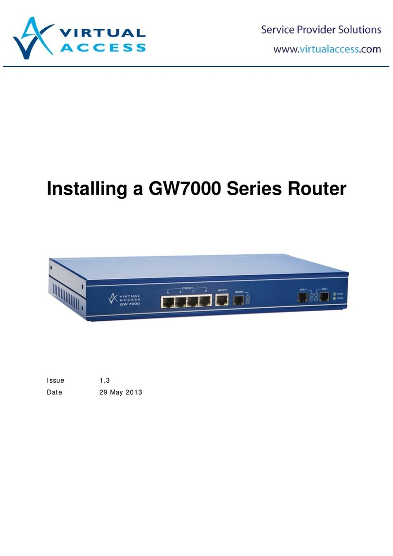
virtual access GW9000 Series Instruction Manual

Installing a GW9000 Series
Router
Issue: 2.0
Date: 09 December 2014

Table of Contents
______________________________________________________________________________________________________
1Virtual Access support details.......................................................................3
1.1 Email support...........................................................................................3
1.2 Telephone support ....................................................................................3
1.3 Website documentation .............................................................................3
2GW9000 pack contents.................................................................................4
3Installing a GW9000 series router................................................................5
3.1 Locating the serial number.........................................................................5
3.2 GW9000 model variations ..........................................................................5
3.3 Rack mounting a GW9000..........................................................................6
3.4 Connecting a GW9000 ADSL router.............................................................6
3.5 Connecting a GW9000 router with a serial connection....................................7
3.6 Connecting an E1/T1 connection.................................................................8
3.7 Connecting a 3G connection.......................................................................8
3.7.1 3G specifications.................................................................................9
3.7.2 Inserting a SIM card............................................................................9
3.7.3 3G signal quality.................................................................................9
3.8 Connecting a GW9000 public Ethernet connection....................................... 10
3.9 Connecting multi-I/O cables on a GW9000 ................................................. 10
3.10 Connecting to the RS2323 ports ............................................................... 12
3.11 Connecting to the RS485 ports ................................................................. 13
4GW9000 installation summary....................................................................14
______________________________________________________________________________________________________
© Virtual Access 2014
Installing a GW9000 Series Router
Issue 2.0 Page 2 of 14

Error! Reference source not found.: Error! Reference source not found.
______________________________________________________________________________________________________
1Virtual Access support details
Virtual Access support is available in agreement with your support SLA.
You can contact Virtual Access support by telephone or email. Alternatively, you
can access our website for configuration guides and user manuals.
1.1 Email support
Email support is available 24 hours a day depending on your support SLA. To
enable us to deal with your query efficiently, please include a detailed
description of the issue, what has been done to try and resolve the issue and the
serial number of your router.
1.2 Telephone support
If you would like to talk to one of our support team, phone support is available
24 hours a day depending on your support SLA. To enable us to deal with your
query efficiently, please include a detailed description of the issue, what has
been done to try and resolve the issue and the serial number of your router.
•UK technical support:
0870 850 2937
•Non-UK technical support:
+353 1 604 1842
1.3 Website documentation
The Virtual Access website contains a large amount of support documentation.
Customers have full access to all documentation on the website.
For information on how to configure your GW9000 Series router, read ‘How to
Configure the GW9000 Service Managed Gateway.
Click the following link to access the customer support page.
http://www.virtualaccess.com/customer-support.php
For help with advanced configuration of the GW9000, click the following link.
http://www.virtualaccess.com/smg-docs/start.htm
______________________________________________________________________________________________________
© Virtual Access 2014
Installing a GW9000 Series Router
Issue 2.0 Page 3 of 14

Error! Reference source not found.: Error! Reference source not found.
______________________________________________________________________________________________________
2GW9000 pack contents
Check that you have all the components listed below.
Table 1: Components for installing your GW9000
1x GW9000
1x purple ADSL cable Both ends of the cable looks like this:
1x purple dial modem cable for PSTN Both ends of the cable looks like this:
1x yellow Ethernet cable. Both ends of the cable look like this:
If your GW9000 Series router has a
serial port, you need a serial cable. We
do not provide a serial cable with the
GW9000 Series.
Contact your distributor to purchase a serial cable that complies
with the interface that you use.
Your GW9000 Series router has 4 RS-
232 serial ports and 2 RS485 ports.
Generally these cables are not supplied
as the devices connecting to the
GW9000 often have proprietary pin
assignments. If you need a cable, please
request prior to shipment.
1x regional power cable.
AC Power
DC Power
100V-240V AC,
20 Watts
IEC mains
connector
DC -48V ± 10%
DC power input
Dual power feed
2 x multi-I/O cables to connect to the
analogue inputs, digital inputs and
digital outputs (optional).
1 x antenna (for 3G models only).
2 x rack mounting brackets (may vary
from image shown)
______________________________________________________________________________________________________
© Virtual Access 2014
Installing a GW9000 Series Router
Issue 2.0 Page 4 of 14

Error! Reference source not found.: Error! Reference source not found.
______________________________________________________________________________________________________
3Installing a GW9000 series router
3.1 Locating the serial number
When you receive your GW9000 package, retain the outer packaging. The label
containing the model number, serial number (S/N) and part number (P/N) is
located on the side of the packaging box.
Each router is assigned a unique serial number. Record your router’s serial
number on a printed copy of your warranty or somewhere you can easily access
it. You must reference your unique serial number when you contact your
distributor or Virtual Access support for installation and configuration information
or if you need to request support help on the device.
Figure 1: The serial label showing serial number and part number
Unpack the contents. There is a matching label located on the bottom of the
router that shows the same S/N and P/N.
3.2 GW9000 model variations
Use the table below to match your model number. Check that all the parts are in
the GW9000 package before you install your router.
If there is a ‘Y’ in a field, you should have that part. If there is a ‘2’ in a field,
you should have two parts. If there are any parts missing, please contact your
distributor.
______________________________________________________________________________________________________
© Virtual Access 2014
Installing a GW9000 Series Router
Issue 2.0 Page 5 of 14

Error! Reference source not found.: Error! Reference source not found.
______________________________________________________________________________________________________
Model
Number Port
Description Power
Cable WAN
Connection
Cable
RJ11
(purple)
Modem
(PSTN)
Cable
BT-
RJ11
(black)
Ethernet
Cable
(yellow)
2 x Multi-
I/O
cables
(Optional)
GW9010 Quad Ethernet Y Y - Y Y
GW9025 Quad Ethernet,
V.90 modem Y Y Y Y Y
GW9110 Quad Ethernet,
ADSL Y Y - Y Y
GW9125 Quad Ethernet,
ADSL, V.90
modem
Y Y Y Y Y
Table 2: GW9000 model numbers and parts
In addition to the interfaces listed above, there are also options for the following
interfaces.
3G
HSPA, UMTS, EDGE, GPRS, GSM
E1/T1
Configurable as framed or unframed
Serial
V.24, V.35, V.36 or X.21 synchronous serial WAN
Table 3: Optional GW9000 interfaces
3.3 Rack mounting a GW9000
You can rack mount a GW9000 router in a 19-inch rack. The rack mountable
brackets along with screws are included in the GW9000 package. You will need a
Philips screwdriver to tighten the screws in the rack.
3.4 Connecting a GW9000 ADSL router
Figure 2: Connecting an ADSL connection
On your GW9000 Series router, connect one end of the yellow RJ45 Ethernet
cable to the Ethernet port marked A. Connect the other end into the LAN port of
your PC or to a LAN hub.
______________________________________________________________________________________________________
© Virtual Access 2014
Installing a GW9000 Series Router
Issue 2.0 Page 6 of 14

Error! Reference source not found.: Error! Reference source not found.
______________________________________________________________________________________________________
Connect the RJ11 end of the purple cable to the port marked DIAL MODEM.
Connect the other end to the ADSL socket on the wall or to the splitter. This
socket can be an RJ45 or an RJ11 port. The RJ11 connector will fit into both.
To connect directly to an ADSL service, connect one end of the RJ11 connector
on a purple cable to the port marked ADSL-0. Connect the other end of the RJ11
connector to the ADSL socket on the wall. This socket can be an RJ45 or an RJ11
port. The RJ11 connector will fit into both.
If you are using a cable modem or ADSL modem and not a direct service
connection, do not connect the ADSL cable. Connect on end of the Ethernet
cable to the appropriate Ethernet port on the router. Connect the other end to
the Ethernet port on your cable modem or ADSL modem.
Connect the power supply connector to the power port on the back of the router.
The config LED on the front of the router will flash if it is in factory config mode.
If the router is pre-configured the config LED will be solid.
3.5 Connecting a GW9000 router with a serial connection
Figure 3: Serial and power connections on the rear of a GW9000 series router
If you are using a serial connection, connect the serial cable to the serial port on
the back of the router.
Connect the power supply to the power port on the back of the router.
The config LED on the front of the router will flash if it is in factory config mode.
If the router is pre-configured the config LED will be solid.
If your serial connection is configured and connected to the network correctly,
the serial SYNC LED will be lit and solid. If data is transmitting correctly across
the serial link, the data LED will blink intermittently. If the LEDs on your router
______________________________________________________________________________________________________
© Virtual Access 2014
Installing a GW9000 Series Router
Issue 2.0 Page 7 of 14
Error! Reference source not found.: Error! Reference source not found.
______________________________________________________________________________________________________
are not correctly lit, check that the cables are attached correctly and your
service has been enabled by your provider.
3.6 Connecting an E1/T1 connection
Figure 4: Connecting an E1/T1 connection
For a standard connection, connect one end of the E1/T1 cable to the E1/T1 port
on the back of the router and the other end of the cable to an E1/T1 switch.
For a back-to-back connection, connect one end of an E1/T1 cross over cable to
the E1/T1 port on the back of the router. Connect the other end of the cable into
the E1/T1 port of another device.
Connect the power supply connector to the power port.
The config LED on the front of the router will flash if it is in factory config mode.
If the router is pre-configured the config LED will be solid.
If your E1/T1 connection is configured and connected to the network correctly,
the E1/T1 SYNC LED will be lit and solid. If data is transmitting correctly across
the E1/T1 link, the data LED will blink intermittently. If the LEDs on your router
are not correctly lit, check that the cables are attached correctly and your
service has been enabled by your provider.
3.7 Connecting a 3G connection
WARNING
The SIM card MUST be inserted into the SMG before the unit is powered on.
Do not insert or remove the SIM card after the unit has been powered on.
The GW9000 Series router contains a 3G module.
______________________________________________________________________________________________________
© Virtual Access 2014
Installing a GW9000 Series Router
Issue 2.0 Page 8 of 14

Error! Reference source not found.: Error! Reference source not found.
______________________________________________________________________________________________________
3.7.1 3G specifications
Air Interface GSM/GPRS/EDGE/WCDMA/HSPA
Frequency
Bands GSM/GPRS/EDGE: 850/900/1800/1900
WCDMA/HSPA: 850/1900 or 900/2100
Speed
GPRS/EDGE D/L: 247.4 Kbps
U/L: 123.7 Kbps
HSPA D/L: 7.2 Mbps
U/L: 5.76 Mbps
Certification FCC, CE, R&TTE, PTRCB, GCF, Operator and Infrastructure IOT
Table 4: 3G specifications for the GW9000
3.7.2 Inserting a SIM card
Ensure the GW9000 Series router is powered off.
Hold the SIM card with the chip side face down and cut corner top left.
Figure 5: Position of the SIM card
Gently push the SIM card into SIM slot 1 until it clicks in.
To remove the SIM card, gently push the SIM card. The card will click out.
Attach the antenna to the antenna connector beside the SIM slot.
Connect the power supply connector to the power port.
The power LED will light if the 3G card is receiving power and functioning
correctly. The DATA LED will blink intermittently when data is being transmitted
over the link.
If the LEDs on your GW9000 Series router are not correctly lit, check that the
cables are attached correctly and that your service has been enabled by your
provider.
3.7.3 3G signal quality
When connecting 3G it is important to take note of the 3G signal quality and
strength. To check the signal type and strength, connect one of the Ethernet
ports on the GW9000 to your PC.
Open a web browser and browse to the address of the router. If the router is in
factory config the default IP address is 192.168.100.1/24. To view a summary
______________________________________________________________________________________________________
© Virtual Access 2014
Installing a GW9000 Series Router
Issue 2.0 Page 9 of 14

Error! Reference source not found.: Error! Reference source not found.
______________________________________________________________________________________________________
of your 3G connection, on the start page, click Status -> 3G info. The 3G
status page appears showing a summary of your 3G connection statistics.
<= -113dBm
No connection
-113dBm, <-89dBm
Low signal strength, connection not reliable
= -89dBm, < -69dBm
Medium signal strength, good connection
>= -69dBm
High signal strength, excellent connection
Table 5: Signal strength qualities
3.8 Connecting a GW9000 public Ethernet connection
Figure 6: Connecting a public Ethernet connection
On your GW9000 Series router, connect one end of a yellow RJ45 Ethernet cable
to the Ethernet port marked A. Connect the other end into the LAN port of your
PC or to a LAN switch.
Connect one end of the Ethernet cable supplied by your service provider to any
of the Ethernet ports on the router. The other end of the Ethernet cable will
already be connected to the switch or socket provided by your service provider.
Connect the power supply connector to the power port on the back of the router.
If the LEDs on your GW9000 Series router are not correctly lit, check that the
cables are attached correctly and that your service has been enabled by your
provider.
3.9 Connecting multi-I/O cables on a GW9000
Figure 7: Connecting a multi-I/O connection
______________________________________________________________________________________________________
© Virtual Access 2014
Installing a GW9000 Series Router
Issue 2.0 Page 10 of 14

Error! Reference source not found.: Error! Reference source not found.
______________________________________________________________________________________________________
To connect the analogue inputs, digital inputs and outputs to third party
equipment, the multi-I/O cables must be connected to the analogue-digital
ports.
Cabling
Element DB44
Pin Colour First Cable Signal Second Cable
Signal
1
4
WHITE-Blue
Digital Input #0
Digital Input #14
1
5
BLUE-White
Digital Supply #0
Digital Supply #14
2 6 WHITE-Orange Digital Input #1 Digital Input #15
2 7 ORANGE-White Digital Supply #1 Digital Supply #15
3 8 WHITE-Green Digital Input #2 Digital Input #16
3 9 GREEN-White Digital Supply #2 Digital Supply #16
4 10 WHITE-Brown Digital Input #3 Digital Input #17
4 11 BROWN-White Digital Supply #3 Digital Supply #17
5 12 WHITE-Grey Digital Input #4 Digital Input #18
5 13 GREY-White Digital Supply #4 Digital Supply #18
6 14 RED-Blue Analogue Input - #0 Analogue Input - #2
6 15 BLUE-Red Analogue Input + #0 Analogue Input + #2
7
19
RED-Orange
Digital Input #5
Digital Input #19
7
20
ORANGE-Red
Digital Supply #5
Digital Supply #19
8 21 RED-Green Digital Input #6 Digital Input #20
8 22 GREEN-Red Digital Supply #6 Digital Supply #20
9 23 RED-Brown Digital Input #7 Digital Input #21
9 24 BROWN-Red Digital Supply #7 Digital Supply #21
10 25 RED-Grey Digital Input #8 Digital Input #22
10 26 GREY-Red Digital Supply #8 Digital Supply #22
11 27 BLACK-Blue Digital Input #9 Digital Input #23
11 28 BLUE-Black Digital Supply #9 Digital Supply #23
12 29 BLACK-Orange Analogue Input - #1 Analogue Input - #3
12 30 ORANGE-Black Analogue Input + #1 Analogue Input + #3
13 33 BLACK-Green Digital Input #10 Digital Input #24
13
34
GREEN-Black
Digital Supply #10
Digital Supply #24
14 35 BLACK-Brown Digital Input #11 Digital Input #25
14 36 BROWN-Black Digital Supply #11 Digital Supply #25
15 37 BLACK-Grey Digital Input #12 Digital Input #26
15 38 GREY-Black Digital Supply #12 Digital Supply #26
______________________________________________________________________________________________________
© Virtual Access 2014
Installing a GW9000 Series Router
Issue 2.0 Page 11 of 14

Error! Reference source not found.: Error! Reference source not found.
______________________________________________________________________________________________________
16 39 YELLOW-Blue Digital Input #13 Digital Input #27
16 40 BLUE-Yellow Digital Supply #13 Digital Supply #27
17 1 YELLOW-Orange Relay Closed #0 Relay Closed #2
17 2 ORANGE-Yellow Relay Common #0 Relay Common #2
18 3 YELLOW-Green Relay Open #0 Relay Open #2
18 16 GREEN-Yellow Relay Closed #1 Relay Closed #2
19 17 YELLOW-Brown Relay Common #1 Relay Common #3
19 18 BROWN-Yellow Relay Open #1 Relay Open #3
20 31 YELLOW-Grey Isolated Ground #0 Isolated Ground #1
20
32
GREY-Yellow
Isolated Ground #0
Isolated Ground #1
Table 6: Multi-I/O cable pin assignment
3.10 Connecting to the RS2323 ports
The GW900 has 6 RS232 ports and are presented as an RJ45 port.
Signal Name PIN Number
RTS 1
DTR 2
TxD 3
GND 4
GND 5
RxD 6
DSR 7
CTS
8
Table 7: The pin assignment for RS232
DB9
RJ45
Receive Data 2 3
Transmit Data 3 6
Data Terminal Ready 4 7
Ground (use as shield) 5 5
Ground (use as shield) 5 4
Data Set Ready 6 2
Request to Send 7 8
Clear to Send 8 1
Table 8: RS232 cable: RJ45 to DB9
______________________________________________________________________________________________________
© Virtual Access 2014
Installing a GW9000 Series Router
Issue 2.0 Page 12 of 14

Error! Reference source not found.: Error! Reference source not found.
______________________________________________________________________________________________________
3.11 Connecting to the RS485 ports
The GW9000 has two RS485 ports and are presented as an RJ45 port.
Signal Name PIN Number
TX- Pin 2
TX+ Pin 3
RX+ Pin 6
RX- Pin 7
Table 9: Pin assignment for the RS485 port
______________________________________________________________________________________________________
© Virtual Access 2014
Installing a GW9000 Series Router
Issue 2.0 Page 13 of 14

Error! Reference source not found.: Error! Reference source not found.
______________________________________________________________________________________________________
4GW9000 installation summary
1. Rack mount the GW9000 in a 19-inch rack.
2. If you are installing a 3G model, the SIM card must be inserted into the router before
it is powered on. Do not insert or remove the SIM card after the unit has been
powered on.
3. Using the pin assignment in section 3.9, connect the multi-I/O cable to the analogue
inputs, digital inputs and digital outputs.
4. Connect the WAN link (3G, E1/T1, Ethernet, ADSL).
5. Connect the Multi-I/O cable to the GW9000.
6. Connect the GW9000 RS232 ports to the third party equipment.
7. Connect the power to the unit.
8. Connect an Ethernet port to a PC.
9. Configure the router if it has not been pre-configured.
______________________________________________________________________________________________________
© Virtual Access 2014
Installing a GW9000 Series Router
Issue 2.0 Page 14 of 14
This manual suits for next models
4
Table of contents
Other virtual access Network Router manuals

virtual access
virtual access GW6600 User manual

virtual access
virtual access GW3330 User manual

virtual access
virtual access GW3330 User manual

virtual access
virtual access GW6600 User manual

virtual access
virtual access GW6600 User manual

virtual access
virtual access GW1000M User manual

virtual access
virtual access GW Series Instruction sheet

virtual access
virtual access GW7000 Series Instruction Manual

virtual access
virtual access GW2040 Series User manual

virtual access
virtual access GW6610 User manual