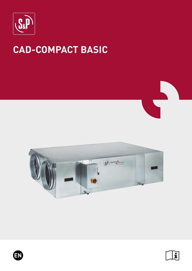
S&P CAD-COMPACT 500 User manual

EN
CAD COMPACT ECOWATT

2
INDEX
1. INTRODUCTION..........................................................................................................................................................................3
2. SAFETY REGULATIONS AND “CE” MARKING............................................................................................................................3
3. GENERAL INSTRUCTIONS.........................................................................................................................................................3
4. UNIT LABELLING.......................................................................................................................................................................3
5. HANDLING .................................................................................................................................................................................4
6. INSTALLATION ..........................................................................................................................................................................4
6.1. INTRODUCTION...................................................................................................................................................................4
6.1.1. Outdoor installation ..................................................................................................................................................5
6.2. Dimensions and free space for maintenance.....................................................................................................................6
6.2.1. Dimensions ...............................................................................................................................................................6
6.2.2. Free space for maintenance .....................................................................................................................................8
6.3. Mounting process of an additional supply filter .................................................................................................................8
6.4. Range specifications ...........................................................................................................................................................9
6.5. Connections.........................................................................................................................................................................9
6.5.1. Connection with air duct...........................................................................................................................................9
6.5.2. Condensate drainage................................................................................................................................................9
6.6. Electrical connection.........................................................................................................................................................10
6.6.1. Wiring diagram .......................................................................................................................................................10
6.6.2. Fan operation without speed regulation. Operation at maximum speed ..............................................................11
6.6.3. Connecting electrical accessories..........................................................................................................................11
6.6.3.1. VAV control (Variable airflow), manual adjustment...................................................................................12
6.6.3.1.1. Manual adjustment by REB-ECOWATT (accessory)...................................................................12
6.6.3.2. VAV Control (variable airflow), with CO2sensor or similar.......................................................................12
6.6.3.3. CAV control (constant airflow) ...................................................................................................................13
6.6.3.4. COP Control (constant pressure) ...............................................................................................................14
6.6.3.5. Pressure switch connection.......................................................................................................................15
6.7. Reverse outdoor air / indoor air side................................................................................................................................16
7. INSPECTION, MAINTENANCE AND CLEANING ......................................................................................................................17
7.1. Filters replacement...........................................................................................................................................................17
7.2. Additional filter installation ..............................................................................................................................................18
7.3. Heat exchanger .................................................................................................................................................................18
7.4. Fans ...................................................................................................................................................................................18
7.5. Condensation drainpipe ....................................................................................................................................................19
8. OPERATION ANOMALIES.........................................................................................................................................................19
8.1. General anomalies............................................................................................................................................................19

3
1. INTRODUCTION
Thank you for purchasing this appliance. It has been manufactured in full compliance with applicable safety regulations
and EU standards.
Please read this instruction book carefully, as it contains important information for your safety during the installation,
use and maintenance of this product.
Keep it at hand for future reference.
Please check that the appliance is in perfect condition when you unpack it, as all factory defects are covered by the S&P
guarantee.
2. SAFETY REGULATIONS AND “CE” MARKING
S&P technicians are firmly committed to research and development of ever more efficient products and in compliance
with current safety regulations.
The instructions and recommendations given below reflect current regulations, principally regarding safety, and the-
refore are based on compliance with general regulations. Therefore, we recommend all people exposed to hazards to
strictly follow the safety regulations in force in your country. S&P will not be held liable for any possible harm or damage
caused by non-compliance with the safety regulations, as well as caused by modifying the product.
The CE mark and the corresponding declaration of conformity are proof of the product’s conformity with current EU
regulations.
3. GENERAL INSTRUCTIONS
A hazard analysis of the product has been carried out as provided in the Machine Directive. This manual contains infor-
mation for all personnel exposed to these hazards, with the aim of preventing possible harm or damage due to faulty
handling or maintenance.
All maintenance operations (ordinary and extraordinary) must be carried out with the machine switched off and the
electrical power supply disconnected.
To avoid a possible accidental start up, place a warning notice on the electrical control panel with the following text:
“Attention: control disconnected for maintenance operations”
Before connecting the power supply cable to the terminal strip, make sure the mains voltage corresponds to the voltage
indicated on the specifications plate of the unit.
Regularly check the product labels. If, due to the passing of time, they are no longer legible, they must be replaced.
4. UNIT LABELLING
The machine may come with several pictograms that must not be removed. These signs are divided into:
• Prohibition signs: Do not repair or adjust when in operation.
• Danger signs: Warning of the presence of live elements inside the container bearing the sign.
• Identification signs: CE card, indicating product information and manufacturer’s address. The CE mark indicates the
product’s conformity with EEC standards.
Danger signs Prohibition signs

4
5. HANDLING
The CAD-COMPACT ECOWATT units are delivered fixed with screws to the pallets.
The handling machines will be adapted to the load and the lifting conditions. In all cases, the lifting will be done at the
device’s base. The centre of gravity is located at the centre of the unit. The device must be carefully manipulated only in
the horizontal position.
6. INSTALLATION
6.1. INTRODUCTION
All models are designed to be installed hanging from the ceiling or located behind a false ceiling. When installing the
unit, is necessary to distribute the unit weigh between the 4 supports existing in the units. Using studded rods (Ø 8 mm),
it can be secured to the ceiling and levelled:
Check the distances between supports in the diagrams of the section: “Dimensions and free dimensions for mainte-
nance”.
The installer must make sure that the ceiling structure and the securing elements can bear the weight of the device,
taking into account that it is a dynamic load.
To prevent the transmission of vibrations from the unit to the rest of the installation, it is necessary that the installer use
specific isolation elements, as well as flexible couplings between the water connections and the pipelines.

5
Model Total weight of unit
(kg)
Anti vibration kit support
(Composed of 4 pcs.)
CAD COMPACT 500 70 KIT AM CAD-COMPACT
CAD COMPACT 900 86 KIT AM CAD-COMPACT
CAD COMPACT 1300 137 KIT AM CAD-COMPACT
CAD COMPACT 1800 145 KIT AM CAD-COMPACT
CAD COMPACT 2500 235 KIT AM CAD-COMPACT
CAD COMPACT 3200 235 KIT AM CAD-COMPACT
CAD COMPACT 4500 336 KIT AM CAD-COMPACT
6.1.1. Outdoor installation
The CAD-COMPACT ECOWATT range is advisable to be mounted indoors. Outdoor mounting is limited to areas
with less extreme climates. When it is installed outdoors,it is preferable to place the unit under a cover which
offers enough protection to prevent rain falling directly to the unit, or install the corresponding rain canopy (acces-
sory). If installed on the ground, sufficient space must be guaranteed under the unit so that it is possible to install
the corresponding siphons in the condensate outlets of the unit.
There is a Kit composed of 4 feet, which facilitates the assembly on floor of these versions: KIT FEET CAD-COM-
PACT.
Both in the case that the KIT FEET CAD-COMPACT is used, and if the unit is based on vibrators or supports made
on site, it is essential that the heat exchanger’s support is guaranteed on 4 existing support points (4 pcs. in the
corners of the unit).
Detail of a CAD-COMPACT with the corresponding canopy and Kit feet
List of necessary accessories needed for outdoor mounting:
Model Pies soporte Tejadillo
CAD COMPACT 500 KIT PIES CAD COMPACT TPP-CAD COMPACT 500
CAD COMPACT 900 KIT PIES CAD COMPACT TPP-CAD COMPACT 900
CAD COMPACT 1300 KIT PIES CAD COMPACT TPP-CAD COMPACT 1300
CAD COMPACT 1800 KIT PIES CAD COMPACT TPP-CAD COMPACT 1800
CAD COMPACT 2500 KIT PIES CAD COMPACT TPP-CAD COMPACT 2500
CAD COMPACT 3200 KIT PIES CAD COMPACT TPP-CAD COMPACT 3200
CAD COMPACT 4500 KIT PIES CAD COMPACT TPP-CAD COMPACT 4500
In addition to the roof and Kit feet, it is necessary to equip the duct network with rain hoods or air intakes equipped
with anti-bird mesh to prevent the entry of animals or objects into the interior of the heat recovery unit.
Avoid condensations in electrical cabinet
In units located in outdoor installation where the heat recovery units stop during the night or during long intervals
of time, it is necessary to:
a) Install isolation dampers in air inlet and air outlet.
b) Add anticondensation devices in the electrical cabinet as: cabinet heating elements that prevent condensation
formation on cabinet surfaces and electronic components.

6
6.2. DIMENSIONS AND FREE SPACE FOR MAINTENANCE
6.2.1. Dimensions
a) CAD-COMPACT 500 to 1800 models
A
ØD
F
G
C
B
E
H
I
J
K K
I
J
H
BY DEFAULT (FACTORY SUPPLY)
TOP VIEW
CONFIGURATION RESULT OF SIMPLE
MODIFICATION ON SITE
FAN ACCESS
FILTER
ACCESS
E
OUTDOOR AIR INTAKE
SUPPLY NEW AIR
EXHAUST INDOOR AIR
EXTRACT INDOOR AIR
CONDENSATE OUTLET 1/2"
ELECTRICAL CABINET
E
E
E
FILTER
ACCESS
FILTER
ACCESS
FILTER
ACCESS
FAN ACCESS FAN ACCESS FAN ACCESS
Model A B C D E F G H I J K
CAD-COMPACT 500 1120 698 289 200 862 147 188 1163 546 12 256
CAD-COMPACT 900 1345 843 376 315 1007 190 225 1388 691 12 328
CAD-COMPACT 1300 1495 1218 376 315 1382 190 318 1538 1066 12 403
CAD-COMPACT 1800 1580 1083 453 355 1247 228 285 1623 931 12 393

7
b) CAD-COMPACT 2500 to CAD-COMPACT 4500 models
A
K
C
K
B
E
F
GM
L
E
TOP VIEW
BY DEFAULT (FACTORY SUPPLY)
CONFIGURATION RESULT OF SIMPLE
MODIFICATION ON SITE
J
I
E
H
E
I
H
J
FAN ACCESS
FILTER
ACCESS
OUTDOOR AIR INTAKE
SUPPLY NEW AIR
EXHAUST INDOOR AIR
EXTRACT INDOOR AIR
CONDENSATE OUTLET 1/2"
ELECTRICAL CABINET
E
FILTER
ACCESS
FILTER
ACCESS
FILTER
ACCESS
FAN ACCESS FAN ACCESS FAN ACCESS
Model A B C D E F G H I J K L M
CAD-COMPACT 2500 1845 1495 453 - 1670 127 41 1888 1343 17 385 570 375
CAD-COMPACT 3200 2038 1325 541 - 1489 113 43 2081 1176 12 552 470 450
CAD-COMPACT 4500 2207 1993 598 - 2156 165 79 2250 1844 12 594 700 440

8
6.2.2. Free space for maintenance
W
L
OUTSIDE AIR INTAKE
NEW AIR SUPPLY
INDOOR AIR EXHAUST
INTERIOR AIR EXTRACTION
CONDENSATE OUTLET
BY DEFAULT (FACTORY SUPPLY)
TOP VIEW
CONFIGURATION RESULT OF SIMPLE MODIFICATION ON SITE
ELECTRICITY CUPBOARD
E
E
E
E A
C
H
H
E
E
FF
A
A
C
BB
D
ACCESS TO FANS
ACCESS TO HEAT RECOVERY UNIT
ACCESS TO FILTERS
L
E
E
E
FF
A
A
C
BB
D
TOP VIEW
Model Unit Filters Heat exchanger Fans
L W H H A B H C D H E F
CAD-COMPACT 500 1120 698 289 289 295 300 289 500* / 550** 487 289 500 300
CAD-COMPACT 900 1345 843 376 376 365 300 376 500* / 680** 570 376 500 300
CAD-COMPACT 1300 1495 1218 376 376 555 350 376 500* / 1020** 570 376 580 350
CAD-COMPACT 1800 1580 1083 453 453 490 350 453 500* / 820** 650 453 500 350
CAD-COMPACT 2500 1845 1495 453 453 360 350 453 500* / 650** 650 453 550 350
CAD-COMPACT 3200 2038 1325 541 541 280 300 541 500* / 550** 745 541 550 300
CAD-COMPACT 4500 2207 1993 598 598 440 450 598 500* / 820** 800 598 800 450
* On-site inspection or cleaning (recommended)
** Exchanger disassembly dimension (not recommended)
6.3. MOUNTING PROCESS OF AN ADDITIONAL SUPPLY FILTER
The heat recovery unit is supplied with the filters already installed. F7 (ePM1 70%) in exhaust air and M5 (ePM10 50%)
in supply air. In addition, it is possible to mount a second filter in the unit (accessory) (for more information see section
“Replacing filters”).

9
6.4. RANGE SPECIFICATIONS
Model Diameter
connections
air
(mm)
Nominal
airflow
150Pa**
(m3/h)
Efficiency
heat recovery
unit*
(%)
Electrical
power supply
Maximum
absorbed
power**
(kW)
Maximum
current**
(A)
Weight
(kg)
CAD-COMPACT 500 200 440 82,2 1/230V, 50-60Hz 0,31 2,0 70
CAD-COMPACT 900 315 790 82,0 1/230V, 50-60Hz 0,45 3,2 91
CAD-COMPACT 1300 315 1.120 82,3 1/230V, 50-60Hz 0,88 4,0 120
CAD-COMPACT 1800 355 1.670 82,7 1/230V, 50-60Hz 1,02 4,2 150
CAD-COMPACT 2500 570x375 2.180 83,5 1/230V, 50-60Hz 0,92 3,9 200
CAD-COMPACT 3200 470x450 3.000 83,7 1/230V, 50-60Hz 2,00 8,7 235
CAD-COMPACT 4500 700x440 4.165 84,6 3/400V, 50-60Hz 2,76 4,2 336
* Wet efficiency referred to nominal airflow, external conditions (-5ºC 80% RH) and interior (20ºC / 50% RH).
** Sum of both fans.
6.5. CONNECTIONS
6.5.1. Connection with air duct
The fans are always blowing out with regard to the machine. Before making the connection of air lines, verify
existing identification labels in each mouth of the heat recovery units.
SUPPLY AIR
AIRE DE IMPULSIÓN
IMMISSIONE
AIR SOUFFLÉ
ZULUFT
EXTRACT AIR
AIRE DE EXTRACCIÓN
ESTRAZIONE DAL LOCALE
AIR REPRIS
ABLUFT
EXHAUST AIR
AIRE DE EXPULSIÓN
ESPULSIONE ALL ESTERNO
AIR REJETÉ
FORTLUFT
OUTDOOR AIR
AIRE EXTERIOR
ARIA DI RINNOVO
AIR NEUF
AUSSENLUFT
Exhaust air
Aire de expulsión
Espulsione all esterno
Air rejeté
Fortluft
Outdoor air
Aire exterior
Aria di rinnovo
Air neur
Aussenluft
Supply air
Aire de impulsión
Inmissione
Air Soufflé
Zuluft
Extract air
Aire de extracción
Estrazione dal locale
Air repris
Abluft
6.5.2. Condensate drainage
The units are supplied with 2 drains (one for each circuit). For added security it has to connect two drains to the
drain pipe of the building. Drain tips are 1/2 “GM threaded.
Drainage system
• To ensure the removal of draining condensate from the tray a siphon must be installed with pressure head diffe-
rence in mmWG greater than the pressure provided by the fan.
• The horizontal sections should have a minimum slope of 2%.
min. 80mm
=
=
Conexionado a la
línea de condensados
Condensation
connection
The siphon should always be full of water. Check its level periodically, refilling it if necessary. An empty siphon
can cause the condensate tray to overflow and water leak through the equipment enclosure.

10
6.6. ELECTRICAL CONNECTION
The CAD-COMPACT ECOWATT range are supplied without a complete operating control integrated in the unit. The elec-
trical components included in the unit (fans, by-pass servomotor, filter pressure switches and temperature probes)
are supplied wired in an electrical cabinet located in one side of the unit. To access the electrical terminal block and
conveniently make the electrical connection of the accessories it is advisable to remove the connection board, follow the
following sequence:
1. Loosen the 5 screws that are distributed by the cover of the electrical cabinet (Fig. 1)
2. Open the cover and pull the metal plate on which the electrical terminals are located until it is outside the cabinet
(Fig. 2).
3. The electrical cabinet has a PG connector for the electrical power cable. Further of this, in a bag that is supplied
inside the unit, there are 3 more connectors that can be used to route the control wiring to the control accessories or
the control panel of the building. Pass the necessary wiring through the connectors.
4. Make the electrical connection to the control board and put it back inside the electrical cabinet, making it slide throu-
gh the existing guides (Fig. 3).
Fig.1 Fig.2 Fig.3
It is recommended to reduce the wiring lengths of the control maneuvers in order to reduce possible effects of the en-
vironment on the control signals.
To avoid interference that may affect the operation of the unit, it is recommended that the wiring be routed away from
other electrical power lines, motors, refrigeration compressors, frequency inverters or the like.
This equipment complies with the Electromagnetic Compatibility Regulations that are applicable to them.
The use of shielded cables is recommended, although in environments with a high level of electromagnetic disturban-
ces, it may become necessary to shield the wiring using a metal tube.
6.6.1. Wiring diagram
CAD-COMPACT models 500 to 3200 have plug-fans with EC motors 230V supply voltage, while the CAD-COMPACT
4500 model have fans with a three-phase motor.
The electrical wiring consists of two phases: the power supply of the fans and the control wire.
Fans power wiring
The two fans are wired to the switch located on the lid of the electrical cabinet. To power the fans, wire the power
line to the terminals of the switch.
T1
N
N
L1
SUPPLY
FAN
EXTRACT
FAN
ELECTRICAL
POWER SUPPLY
230/I/50‐60Hz
GND
BLUE
BROWN
BLUE
GND
BROWN
GND L1 L3
L2
ELECTRICAL
POWER SUPPLY
400/3/50‐60Hz
BROWN
BLACK
GREY
SUPPLY
FAN
EXTRACT
FAN
GND
BROWN
GREY
BLACK
GND
CAD COMPACT 500 TO 3200 MODELS CAD COMPACT 4500 MODEL

11
Control wiring
The wiring will depend on the needs of each installation as well as the accessories used for it. The following image
shows the functions and identifications of the existing electrical connectors inside the electrical cabinet:
SUP(NTC)
N
L
L
Temp.
Filter (ΔP)
Extract
EXT(NTC)
BLACK/NEGRO Temp.
0‐10V
RELAY+
RELAY‐
+10V
GND
RED/ROJO
BLUE/AZUL
YELLOW/AMARILLO
WHITE/BLANCO
GREEN/VERDE
PINK/ROSA
SUPPLY
FAN
EXH(NTC)
Temp.
0‐10V
RELAY+
RELAY‐
+10V
GND
YELLOW/AMARILLO
WHITE/BLANCO
GREEN/VERDE
PINK/ROSA
BLUE/AZUL
BLACK/NEGRO
RED/ROJO
EXTRACT
FAN
BLACK/NEGRO
RED/ROJO
WHITE/BLANCO
GREEN/VERDE GREEN/VERDE
Filter (ΔP)
Supply
ODA(NTC)
Temp.
WHITE/BLANCO
BLACK/NEGRO
RED/ROJO
BLUE/AZUL
YELLOW/AMARILLO
WHITE/BLANCO
RED/ROJO
BLACK/NEGRO
BY‐PASS
SERVO
SUPPLY FAN
REGULATION
SUPPLY
TEMPERATURE
PROBE
EXHAUST
TEMPERATURE
PROBE
EXTRACT FAN
REGULATION ACTUATION BY-PASS
SERVOMOTOR
PRESSURE SWITCH
EXTRACT FILTER
EXTRACT
TEMPERATURE PROBE
TEMPERATURE PROBE
OUTDOOR AIR
PRESSURE SWITCH
SUPPLY FILTER
The following sections show some of the wiring used for the most common regulations.
6.6.2. Fan operation without speed regulation. Operation at maximum speed
In case that electrical accessories are not used, to regulate the fans speed, it is possible to force their maximum
speed by bridging the terminals + 10V and 0-10V on each fans.
Extract fan
PINK
GREEN
WHITE
YELLOW
BLUE
EXTRACT
FAN
Supply fan
RELAY+
RELAY‐
+10V
0‐10V
GND
SUPPLY
FAN
PINK
GREEN
WHITE
YELLOW
BLUE
RELAY+
RELAY‐
GND
+10V
0‐10V
WITHOUT JUMPER, THE FANS WILL NOT BE RUNNING EVEN IF THEY ARE POWERED.
6.6.3. Connecting electrical accessories
With the existing accessories is possible to perform the fans control as well as the automatic control in VAV (va-
riable airflow) and COP (constant pressure) modes.
Recommended accessories depending on the unit size and the control mode
Model Accessories for the
Variable Air Volume System for CO
2
Accessories for
constant pressure
operation
Accessories
for speed
manual control
Inverter Sensor Inverter Probe Electronic
regulator
CAD COMPACT 500 to 4500 CONTROL CAD-REG AIRSENS CO2 / SC02-AD 0-10V / SC02-G 0-10/V CONTROL AERO-REG** TDP-D* REB-ECOWATT**
* For independent control of the working point of each circuit, the supply and extraction fans must be independently controlled by regulator and pres-
sure probe.
** For independent control of the working point of each circuit, the supply and extraction fans must be controlled with its corresponding electronic
regulator.

12
6.6.3.1. VAV control (Variable airflow), manual adjustment
It is possible to control in VAV mode manually with an external potentiometer. Manual control by external poten-
tiometer REB-ECOWATT (accessory).
6.6.3.1.1. Manual adjustment by REB-ECOWATT (accessory)
Simultaneous control of the supply and extract fans
RELAY +
0-10V
0V
10V
WHITE
YELLOW
WHITE
YELLOW
Extract fan
RELAY -
+10V
0-10V
GND
BLUE
PINK
EXTRACT GREEN
FAN
SUPPLY
FAN
PINK
GREEN
BLUE
+10V
RELAY +
RELAY -
0-10V
GND
Supplyfan
REB-ECOWATT
Independent control of supply and extract fans
10V
REB-ECOWATT
0-10V
0V
Supply fan
Extract fan
PINK
GREEN
WHITE
YELLOW
BLUE
EXTRACT
FAN
RELAY +
RELAY -
+10V
0-10V
GND
SUPPLY
FAN
PINK
GREEN
WHITE
YELLOW
BLUE
0-10V
0V
10V
REB-ECOWATT
+10V
RELAY +
RELAY -
0-10V
GND
6.6.3.2. VAV Control (variable airflow), with CO2sensor or similar
CAD-COMPACT units are equipped with EC motors. The motors have specific terminals for sending a regulation
signal to control fan speed (0-10V). The 0V signal corresponds to the fan stop, while the signal of 10V corresponds
to fan maximum speed.
To perform the speed regulation in VAV with speed control with external sensor of CO2 or similar, it is necessary
to use the accessory CONTROL CAD-REG and the external sensor (see point 7.5.2.4.). In the CONTROL CAD-REG
instruction booklet it is contained the necessary information to carry on the electrical connection of the different
components.

13
6.6.3.3. CAV control (constant airflow)
The inverter is used to guarantee an specific constant air volume in the duct system, regardless of the filters
clogging state.
CAD-COMPACT units are equipped with EC motors. The motors have specific terminals for sending a regulation
signal to control fan speed (0-10V).
The 0V signal corresponds to the fan stop, while the 10V signal corresponds to the maximum fan speed.
To perform speed regulation in pressure or constant airflow mode, it is necessary to use the CONTROL AERO-REG
accessory and the corresponding external TDP-D sensor.
1º Connect the pressure transmitter TDP-D (accessory) to the specific pressure taps there are in the heat recovery
unit. Ensure that pressure taps “+“ and “-“ of the pressure transmitter concides with those of the heat recovery
unit.
+-
-
+
2º Perform the electrical connection and regulator configuration, following the instructions of the CONTROL AE-
RO-REG accessory.
3º Reconfigure the pressure transmitter. So that the regulation is correct and the transmitters correctly visualize
the airflow, it is necessary that it is configured to work in airflow mode with a range of 9,999 m3/h.
Adjustment to work in airflow mode
The selection between pressure and airflow is made by the DIP3(SW1) micro switch existing inside the micro
switch. Fix the micro switch in ON position.

14
Indicate the airflow range
Once configured the airflow measurement, press the “OK” button to set the first digit of factor k. The value flashes
and is adjusted using the buttons “” and “”. When set, press the “OK” button to memorise the factor k. The
actual measured value is displayed. If a airflow range is selected it is not necessary to enter a range of pressures.
Model K factor
CAD-COMPACT 500 28
CAD-COMPACT 900 59
CAD-COMPACT 1300 55
CAD-COMPACT 1800 58
CAD-COMPACT 2500 120
CAD-COMPACT 3200 93
CAD-COMPACT 4500 177
6.6.3.4. COP Control (constant pressure)
Constant Pressure (COP)
This type of regulation is associated to multi-zone ventilation systems in which ventilation multi-room is carried
out by a single heat recovery unit. Flow regulation per zone is done using motorized dampers, so speed regulation
of the fans aims to maintain a constant pressure in the ductwork. The value of this pressure must be determined
by experimenting during the system start-up process.
CAD-COMPACT units are equipped with EC motors. The motors have specific terminals for sending a regulation
signal to control fan speed (0-10V).
The 0V signal corresponds to the fan stop, while the signal of 10V corresponds to fan maximum speed.
To perform the speed regulation in COP mode, it is necessary to use the accessory CONTROL AERO-REG and the
external pressure sensor TDP-D. In the CONTROL AERO-REG instruction booklet it is contained the necessary in-
formation to carry on the electrical connection of the different components.
1º Connect the pressure transmitter TDP-D (accessory) to the duct system where the heat recovery unit is duc-
ted. Ensure that pressure taps “+“ and “-“ coincide with those of the heat recovery unit:
Position of the pressure taps of the TDP-D transmitter in COP systems with control of the extraction pressure
-
TDP-D
(Accessory)
CONTROL
AERO-REG
(Accessory)
EXTRACTION
DUCT OF
BUILDING
DUCT OF NEW
AIR INPUT

15
Position of the pressure taps of the TDP-D transmitter in COP systems with control of the supply pressure
EXTRACTION
DUCT OF
BUILDING
DUCT OF NEW
AIR INPUT
CONTROL
AERO-REG
(Accessory)
TDP-D
(Accessory)
+
6.6.3.5. Pressure switch connection
All CAD-COMPACT range of heat recovery units have differencial pressure switches to perform the control of
polluted filters. The pressure switches are located inside the equipment and wired to the electrical cabinet. If you
want to obtain specific information on the status of the filters through (light or sound indication), it is possible to
carry out an electrical operation by passing the power line through the filter contact.
Filter (ΔP)
Extract
Supply
Filter (ΔP)
32
1
32
1
WHITE / BLANCO
GREEN / VERDE
GREEN / VERDE
WHITE / BLANCO
Control pressure
switch filter EXTRACTION
Filter OK: 1-2 Connuity
Dirty filter: 1-3 Connuity
Control pressure
switch filter SUPPLY
Potenal-free contact
available to perform
external wiring
TERMINALS INDICATION
FILTER STATUS
ELECTRIC CABINET
INSIDE THE UNIT
In any case, it is recommended to use a CONTROL CAD-REG or CONTROL AERO-REG control accessory that, in
addition to the filter supervision functions, integrates other functionalities such as speed regulation, fan fault
control, modbus communication, etc.
Detail of the connection to the CONTROL CAD-REG to enable the control of clogged filters:
1
2
3
18
GND
14 15 16 17
PD
19 20
WHITE / BLANCO
GREEN / VERDE
Filter (ΔP)
Extract
Supply
Filter (ΔP)
GREEN / VERDE
WHITE / BLANCO
32
1
CONTROL CAD-REG
(Accessory)
CAD-COMPACT -ECOWATT
Filter OK: 1-2 Continuous
Dirty filter: 1-3 Continuous

16
Detail of the connection to the CONTROL AERO-REG to enable the control of clogged filters:
3
3
CAD-COMPACT -ECOWATT
Filter OK: 1-2 Continuous
Dirty filter: 1-3 Continuous
CONTROL AERO-REG
(Accessory)
Filter (ΔP)
Extract
Supply
Filter (ΔP)
GREEN / VERDE
2
1
WHITE / BLANCO
2
1
WHITE / BLANCO
GREEN / VERDE
24V
AI1
0V
0V
0V
DI2
DI1
6.7. REVERSE OUTDOOR AIR / INDOOR AIR SIDE
In all units it is possible to reverse the supply and extract air sides.
OUTDOOR FRESH AIR INTAKE
EXHAUST INDOOR AIR
SUPPLY FRESH AIR
EXTRACT INDOOR AIR
FILTERS ACCESS
FANS ACCESS
DEFAULT CONFIGURATION (Factory supplied) SYMMETRICAL CONFIGURATION (Configuration on site)
To carry on this modification it is necessary to make the following modifications to the unit:
1. Exchange the supply and extract filters as well as the access covers to the filters.
2. Replace the labels that identify the function of the air inlet/outlet. To do this, a new set of labels is supplied with the
unit.
OUTDOOR AIR
AIRE EXTERIOR
ARIA DI RINNOVO
AIR NEUF
AUSSENLUFT
EXHAUST AIR
AIRE DE EXPULSIÓN
ESPULSIONE ALL ESTERNO
AIR REJETÉ
FORTLUFT
SUPPLY AIR
AIRE DE IMPULSIÓN
IMMISSIONE
AIR SOUFFLÉ
ZULUFT
EXTRACT AIR
AIRE DE EXTRACCIÓN
ESTRAZIONE DAL LOCALE
AIR REPRIS
ABLUFT

17
3. Replace the electrical connection label existing in the back side of the electrical terminal box with the one symmetri-
cal label supplied in the accessory bag.
4. Only in cold climates where by-pass is used as part of the defrost strategy of the heat exchanger: Reverse the direc-
tion of the by-pass so that it remains at the supply of the unit.
1. Disconnect the heat recovery unit.
2. Remove the side panel (fig.1).
3. Extract carefully the bypass (fig.2).
4. Disconnect the electrical connector that feeds the bypass.
5. Turn the bypass according to image (fig.3 and 4).
6. Reconnect the electrical power connector of bypass.
7. Place the bypass in its housing again (fig.5), close the panel and start up the unit.
Fig.1 Fig.2 Fig.3
5.giF4.giF
180º
7. INSPECTION, MAINTENANCE AND CLEANING
7.1. FILTERS REPLACEMENT
The registers ubication for filters maintenance depends on the model and version. The exact ubication of the filters is
identified by a label in the profile that indicates the type of filter and its characteristics.
FALLING OBJECTS
By loosening the screws that hold the panels, they will be released. In units installed in ceiling, pay spe-
cial attention to this operation to prevent the fall of a panel. During the maintenance signaling the area
below the heat recovery unit and prevent personnel access to it.
Access to filters is done by removing the two registration panels located on the side of the heat recovery unit. To replace
the filters, follow the following sequence:
Fig.3Fig.2Fig.1
1. Access to the filters is done by removing the two existing side panels on the side where the electrical cabinet is located
(Fig.1).
2. Remove the 4 screws that fix the filter access panel. Hold the panel preventing it from falling when loosening the last
screw. (Fig 2).
3. Pull the dirty filter outwards, sliding it on the existing guide.
In the process of assembling the new filter, follow the reverse order, paying attention to the arrow that defines the direc-
tion of the air that you will find in the new S&P filter.

18
Filters spare parts table
Model Accessory filters and spare parts for CAD-COMPACT*
G4 M5 F7 F9
CAD COMPACT 500 AFR-CAD COMPACT 500 G4 AFR-CAD COMPACT 500 M5 AFR-CAD COMPACT 500 F7 AFR-CAD COMPACT 500 F9
CAD COMPACT 900 AFR-CAD COMPACT 900 G4 AFR-CAD COMPACT 900 M5 AFR-CAD COMPACT 900 F7 AFR-CAD COMPACT 900 F9
CAD COMPACT 1300 AFR-CAD COMPACT 1300 G4 AFR-CAD COMPACT 1300 M5 AFR-CAD COMPACT 1300 F7 AFR-CAD COMPACT 1300 F9
CAD COMPACT 1800 AFR-CAD COMPACT 1800 G4 AFR-CAD COMPACT 1800 M5 AFR-CAD COMPACT 1800 F7 AFR-CAD COMPACT 1800 F9
CAD COMPACT 2500 AFR-CAD COMPACT 2500 G4 AFR-CAD COMPACT 2500 M5 AFR-CAD COMPACT 2500 F7 AFR-CAD COMPACT 2500 F9
CAD COMPACT 3200 AFR-CAD COMPACT 3200 G4 AFR-CAD COMPACT 3200 M5 AFR-CAD COMPACT 3200 F7 AFR-CAD COMPACT 3200 F9
CAD COMPACT 4500 AFR-CAD COMPACT 4500 G4 AFR-CAD COMPACT 4500 M5 AFR-CAD COMPACT 4500 F7 AFR-CAD COMPACT 4500 F9
* In serial, the units are supplied with F7 as standard and M5 as extraction. All models allow the assembly of a second filter inside, obtaining, among others,
the following combinations: F7 + F9, M5 + F7 or G4 + F7.
7.2. ADDITIONAL FILTER INSTALLATION
The heat recovery is supplied with mounted filters.
Low pressure F7 filter for supply air and M5 for extract air.
Inside the heat recovery unit there is a specific rail for mounting a second additional filter (supplied as an accessory).
7.3. HEAT EXCHANGER
To perform the heat exchanger cleaning it is necessary to remove it from the unit. The disassembly can be easily done
from the lateral panel:
Core disassembly sequence per side
To disassemble of the heat exchanger follow the following sequence:
• Loosen the screws that hold the side panel. Before releasing the panel, ensure that it is well supported by the opera-
tor, preventing it from falling (Fig. 1).
• Remove the bypass assembly, releasing its electrical connector (Fig. 2).
• Pull the heat exchanger until it is completely removed from the equipment (Fig. 3).
Fig.1 Fig.3Fig.2
7.4. FANS
It is not necessary to access the fan to carry out maintenance tasks, nor to carry out the electrical connection since both
fans are wired to the electrical cabinet. However, it is necessary to leave enough space around the equipment so that it
is possible to access the fans in the event of their failure. Do not install the heat exchanger against a wall or an obstacle
that prevents access to the fans.
In case of need to replace the fan, follow the following sequence:
• Remove the access panel for the affected fan (Fig. 1).
• Release the screws that lock the metal plate on which the fan is mounted (Fig. 2).
• Pull out the plate and once outside, remove the fan and proceed to replace it (Fig. 3).
Fig.1 Fig.2 Fig.3

19
7.5. CONDENSATION DRAINPIPE
Inspect the drainpipe regularly and make sure it is not blocked, if this is the case, remove the obstruction.
Check that the drain pipe was done according to the indication included in the point CONNECTIONS of this manual.
The siphon should always be full of water. Check its level periodically, refilling it if necessary. An empty siphon can cause
the condensate tray to overflow and water leak through the equipment enclosure.
8. OPERATION ANOMALIES
8.1. GENERAL ANOMALIES
Anomaly Cause Solution
Difficult to start. Reduced power supply voltage.
Insufficient static torque of motor.
Check motor specification plate.
Close the air inlets to reach the maximum speed.
Change the motor is necessary.
Contact the S&P Post-Sales service.
Insufficient airflow.
Insufficient pressure.
Blocked pipes and/or inlet points
closed.
Fan obstructed.
Filter overloaded.
Insufficient rotation speed.
Exchanger package blocked.
Clean inlet tubes.
Clean fan.
Clean or replace filter.
Check power supply voltage.
Clean the exchanger.
Reduction in
performance after a period
of acceptable operation.
Leaks in the circuit before and/or after
the fan.
Damaged roller.
Check the circuit and restore original conditions.
Check the impeller and if necessary, replace with an
original spare part.
Contact the S&P post sales service.
New air temperature too
cold.
Outside air -5ºC or less. Insertion of post-heating resistances.
Contact the S&P post sales service.
Insufficient performance of
the exchanger.
Fins dirty. Clean the exchanger.
Formation of frost on the
exchanger.
Outside air below -5ºC. Insertion of pre-heating devices (anti-ice).
Contact the S&P Customer Advice service.
Air pulsation. Fan working in excessively low flow
conditions.
Flow instability, obstruction or
bad connection.
Modification of the circuit and/or replacement of the
fan. Clean and/or readjust the inlet channels.
Operate the electronic regulator, increasing the
minimum speed (insufficient voltage).
Contact the S&P Customer Advice service.
There is water inside the
unit.
Drain clogged or wrongly
dimentioned.
Check if exists a body/object obstructing the
passage of water and remove it. Verify that the drain
trap exists and is correctly sized according to the
instructins of this manual.

S&P SISTEMAS DE VENTILACIÓN, S.L.U.
C. Llevant, 4
Polígono Industrial Llevant
08150 Parets del Vallès
Barcelona - España
Tel. +34 93 571 93 00
www.solerpalau.com
Ref. 9023119000
Other manuals for CAD-COMPACT 500
1
This manual suits for next models
6
Table of contents
Other S&P Air Handler manuals