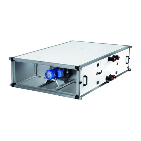
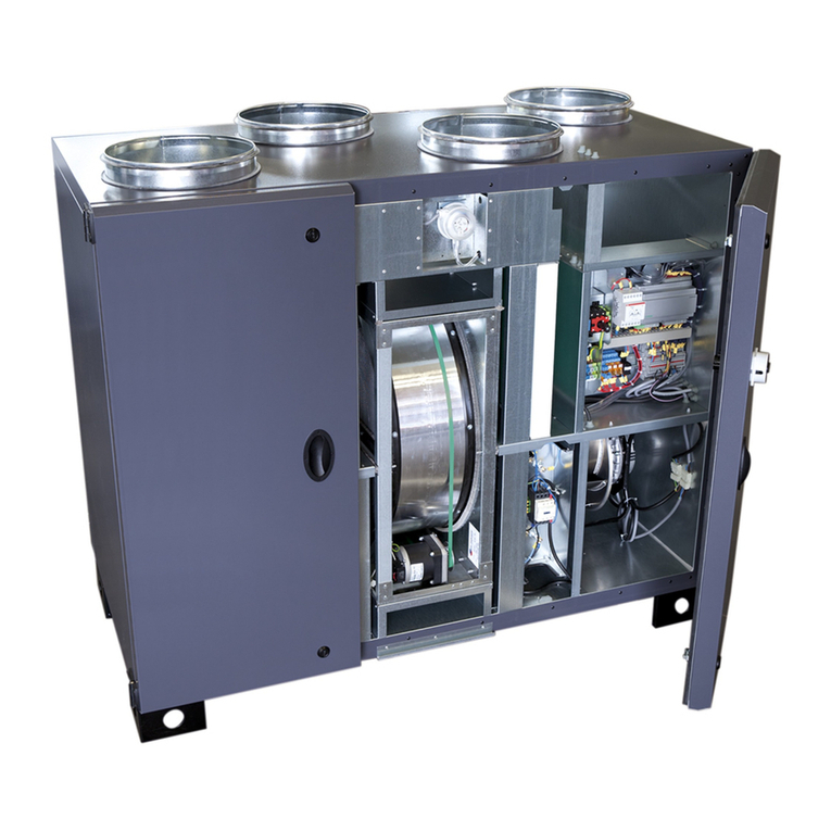
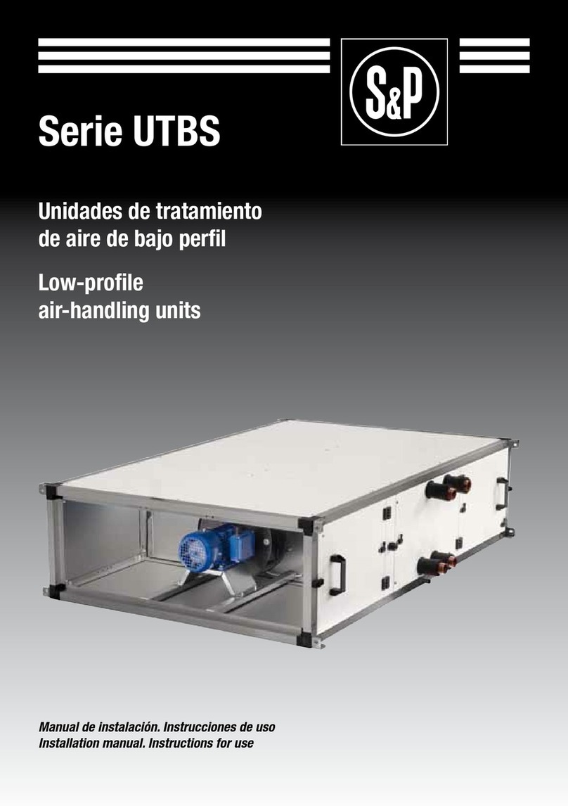
S&P UTBS PRO-REG Series User manual

SERIE UTBS PRO-REG
EN


3
INDEX
1. OVERVIEW .........................................................................................................................................5
2. SAFETY STANDARDS AND “EC” MARKING ........................................................................................5
3. GENERAL STANDARDS.......................................................................................................................5
4. UNIT LABELING ..................................................................................................................................6
5. TECHNICAL CHARACTERISTICS.........................................................................................................6
6. HANDLING .........................................................................................................................................8
7. INSTALLATION...................................................................................................................................10
7.1. Overview .....................................................................................................................................10
7.2. Identification unit parts ..............................................................................................................11
7.3. Installation site...........................................................................................................................11
7.4. Maintenance space.....................................................................................................................11
7.4.1. Dimensions .....................................................................................................................12
7.4.2. Space for maintenance...................................................................................................15
7.5. Assembling the modules............................................................................................................17
7.5.1. Additional filters mounting.............................................................................................18
7.5.2. Assembling flexible connections.................................................................................... 18
7.5.3. Mixing module installation .............................................................................................19
7.5.4. Installation with isolation damper..................................................................................19
7.6. Connecting the unit to the duct system ..................................................................................... 21
7.7. Direct expansion coils connection (DX)...................................................................................... 22
7.8. Drainage system.........................................................................................................................23
7.9. Electrical connection..................................................................................................................23
7.10. Temperature probes location ................................................................................................... 24
8. START-UP PROCEDURE ...................................................................................................................26
9. CONTROL FUNCTIONS......................................................................................................................27
10. CONTROL DIAGRAM..........................................................................................................................29
11. REMOTE CONTROL OPERATION.......................................................................................................32
11.1. Change language......................................................................................................................32
11.2. Simplified menus / accesses....................................................................................................32
11.2.1. User level ......................................................................................................................32
11.2.2. Installer level ................................................................................................................33
11.3. Operation fan modes ................................................................................................................35
11.3.1. Constant airflow operation (CAV) .................................................................................35
11.3.2. Variable airflow operation (VAV) ...................................................................................37
11.3.3. Constant pressure operation (COP)..............................................................................38
11.3.4. Control slave of an external fan (For all working modes)............................................41
11.4. Postheater control....................................................................................................................42
11.4.1. Constant supply air temperature maintenance ...........................................................42
11.4.2. Constant ambient temperature maintenance.............................................................. 42
11.4.3. Temperature set point adaptation vs. outdoor temperature........................................43
11.4.4. Automatic control mode ...............................................................................................43
11.5. Initial temperature setpoint .....................................................................................................43
11.6. Time programming...................................................................................................................44
11.7. Mixing module control (3 Ways) ...............................................................................................47
11.7.1. Without mixing module................................................................................................. 47
11.7.2. CO2control ....................................................................................................................47
11.7.3. Temperature control..................................................................................................... 47
11.7.4. CO2control and temperature........................................................................................ 47
ENGLISH

4
11.8. Control of isolation damper .....................................................................................................47
12. BOOST FUNCTION (only available in CAV and COP modes) .............................................................48
13. REMOTE STOP-START....................................................................................................................... 48
14. FREE COOLING BY NIGHT................................................................................................................. 49
15. WATER HEATER FROST PROTECTION..............................................................................................50
16. RESET THE CORRIGO CONTROLLER................................................................................................ 50
17. CONNECTION TO BUILDING MANAGEMENT SYSTEMS (BMS)........................................................53
17.1. RTU Modbus .............................................................................................................................53
17.2. TCP/IP Bacnet ..........................................................................................................................54
18. REPLACEMENT OF THE BATTERY FROM THE CORRIGO PROGRAMMABLE
LOGIC CONTROLLER ........................................................................................................................54
19. OPERATION ANOMALIES .................................................................................................................55
19.1. General anomalies ...................................................................................................................55
19.2. Failure list ................................................................................................................................56
20. EMERGENCY OPERATIONS...............................................................................................................57
21. PREVENTIVE MAINTENANCE ...........................................................................................................57
21.1. Water coils ................................................................................................................................58
21.1.1. DX coils.......................................................................................................................... 58
21.2. Drainage system....................................................................................................................... 58
21.3. Motors....................................................................................................................................... 58
21.4. Fans .......................................................................................................................................58
21.5. Filters .......................................................................................................................................58
21.5.1. Replacing the filter in the main unit and side-by-side or stacked recovery unit ........59
21.5.2. Replacing filters for in-line recovery modules.............................................................60
21.6. Coils .......................................................................................................................................60
21.7. Dampers ...................................................................................................................................60
21.8. Silencers ...................................................................................................................................61
21.9. Connecting the unit to the water network ...............................................................................61
22. WIRING DIAGRAMS ...........................................................................................................................62

5
1. OVERVIEW
• We appreciate the trust you have placed in us by purchasing this device. You have pur-
chased a high-quality product that has been manufactured in strict compliance with re-
cognized technical regulations regarding safety, and in accordance with EC standards.
• Read this instruction booklet carefully, since it contains important information for your
safety during the installation, use and maintenance of this product.
• Keep this booklet in case you need to consult it in the future.
• We ask that you make sure the equipment is in perfect condition when you unpack it,
since any existing defect is covered by the S&P warranty.
• Technicians responsible for installing, start-up and maintenance must read the instruc-
tions and be familiar with them before starting work.
2. SAFETY STANDARDS AND “EC” MARKING
• S&P engineers are firmly committed to research and development to achieve products
with improved efficiency that complies with current safety standards.
• The standards and recommendations indicated below reflect current standards in the
field of safety, and therefore are based primarily on meeting standards of a general na-
ture. Consequently, we recommend that all personnel exposed to risks adhere strictly to
local regulations in force regarding hazard prevention.
• S&P is in no way responsible for any damage or injury caused to persons or objects
resulting from failure to comply with safety standards, and any possible modifications
to the product. The EC seal and statement of conformity serve as proof of the product’s
compliance with applicable European Community standards.
3. GENERAL STANDARDS
• Product risks have been analysed pursuant to the provisions of the Machinery Directive.
This manual contains information intended for all personnel exposed to hazards, with
the goal of preventing personal injuries or damage to objects resulting from mishand-
ling or improper maintenance. All maintenance service work (corrective and preventive)
must be performed with the equipment stopped and disconnected.
• To avoid danger of possible accidental start up ensure that the equipment is electrically
isolated and locked. If this is not possible, warning signs should be placed on main dis-
tribution console that state:
“WARNING: controls disconnected for maintenance”
• Before connecting the power cable to the motors, make sure that the voltage on the line
matches the voltage indicated on the unit’s identification plate.

6
4. UNIT LABELING
• The unit comes with a variety of labels that must not be removed. Herewith sample la-
bels and meaning:
ICON / LABEL MEANING
Signing on fan access door. Indicates
that the equipment must be disconnec-
ted, followed by a waiting period, since
there are moving parts that constitute
danger to entry.
Indicates direction of airflow in the unit.
Indicates the inlet/outlet for the cold
water heat exchanger.
Indicates the inlet/outlet for the hot
water heat exchanger.
Unit identification plate. This indicates:
- Model
- Code
- Serial number
- Date of manufacture
- Output power of installed motors (Kw)
-
Maximum absorbed current of motor (A)
- Power of installed electric heater
- Electrical supply
5. TECHNICAL CHARACTERISTICS
Ventilation section
Sizes 2 and 3 have one fan, whereas sizes 5 and 8 have two. For each size, there is a motor
power settings to ensure highest efficiency at the required working point. The regulation
via frequency converter allows a high efficiency in the requested working-point.

7
Example: left side registerExample: left s
i
de re
gi
ste
Model
UTBS PRO-REG Maximum airflow (m3/h) Motor
Power
(kW)
Frequency
range
(Hz)
Chilled coil/DX Hot coil Without coils
2 1300 1500 1500 1x0,55 20-55
3 2500 2500 2500 1x0,75 20-50
5 3800 4500 5100 2x0,75 20-50
8 6500 7400 7500 2x1,1 20-50
Model
UTBS
PRO-REG Air
flow
(m
3
/h)
Coils Thermal power (kW)
Inlet/Outlet
connections
Hot water coil Chilled water coil
H2 H4 C4 C6
80ºC/60ºC 50ºC/45ºC 80ºC/60ºC 50ºC/45ºC 7ºC/12ºC 7ºC/12ºC
2900 11,9 8,3 18,2 22,7 8,1 9,6 1-1/4” GM
1200 14,4 10,0 22,7 15,5 10,0 11,9
31700 23,5 16,0 34,7 23,5 15,5 20,0 1-1/4” GM
2500 30,5 20,9 46,8 31,9 20,5 23,3
52500 33,9 23,3 51,2 34,7 23,2 29,2 1-1/4” GM
3500 42,7 29,4 66,6 45,2 29,6 38,4
84000 55,0 37,7 81,4 55,4 36,0 46,8 1-1/2” GM
6000 72,5 49,8 111,5 76,1 48,2 64,8
* Air inlet temperature: -5ºC, Rel. Hum: 80%.
** Air inlet temperature: 32ºC, Rel. Hum: 50%.
Coil section
Water coils
In the section it can be included one or two water coils (one heating or one cooling coil or
both at the same time). The units can be supplied with 2 or 4 rows for heating coils and 4 or
6-rows for cooling coils. If the unit includes a cooling coil it is always supplied as a standard
with condensate drip tray made for stainless steel AISI 304 and a droplet eliminator. The
connections of the water coil and the drip tray can be ordered on left side or right side of
the unit.

8
Model Available electric power / Stages
UTBS-2 E3 4,5 kW/ 1et. E2 15,0 kW/ 2et.
UTBS-3 E6 6,0 kW/ 1et. E7 15,0 kW/ 2et. E2 24,0 kW/ 2et.
UTBS-5 E4 9,0 kW/ 2et. E1 15,0 kW/ 2et. E3 36,0 kW/ 3et.
UTBS-8 E1 15,0 kW/ 2et. E4 24,0 kW/ 2et. E3 45,0 kW/ 3et.
COOLING HEATING
Airflow Volum
(dm
3
)
Denom. Nº
stages
Ø
Distributor
(Liquid line)
Ø
Colector
(Gas line)
Power*
(kW)
Power**
(kW)
Supply
air
temp.
(°C)
Supply
air
temp.
(°C)
Rel.hum.
(%)
Rel.hum.
(%)
R410A
Airflow
(%)
R410A
Airflow
(%)
(m
3
/h)
ΔP
R410A
aFW
ΔP
R410A
(aFW)
UTBS-2 1250 1,2 1 1/2” 3/4” 4,6 14,2 87 84,6 14,96 4,9 32,7 25 87,9 9,6
UTBS-3 2500 2,21 1 5/8” 3/4” 8,8 14,4 87 163,3 13,00 8,0 33,6 28 143,4 6,1
UTBS-5 3500 2,41 1 5/8” 3/4” 10,9 15,2 85 200,0 10,90 10,0 32,7 30 180,2 5,1
UTBS-8 6000 4,4 1 5/8” 3/4” 19,9 14,9 86 368,3 22,10 17,2 32,7 30 310,1 8,8
COOLING HEATING
UTBS-2 1250 2 1 5/8” 3/4” 10,0 14,5 94 185,3 8,60 10,5 34,4 17 190,5 5,10
UTBS-3 2500 3,31 1 5/8” 3/4” 19,4 14,9 94 358,6 25,30 19,9 30,8 18 359,0 13,70
UTBS-5 3500 4,3 1 5/8” 7/8” 26,6 15,2 94 490,5 18,60 27,6 30,6 18 498,0 10,30
UTBS-8 6000 8,4 2 5/8” 7/8” 47,8 14,6 94 882,0 25,30 49,8 31,8 17 897,0 12,30
Airflow Volum
(dm
3
)
Denom. Nº
stages
Ø
Distributor
(Liquid line)
Ø
Colector
(Gas line)
Power*
(kW)
Power**
(kW)
Supply
air
temp.
(°C)
Supply
air
temp.
(°C)
Rel.hum.
(%)
Rel.hum.
(%)
R410A
Airflow
(%)
R410A
Airflow
(%)
(m
3
/h)
ΔP
R410A
aFW
ΔP
R410
aFW
Electric heaters
The unit can be supplied with electric heaters made of shielded resistances with a galva-
nised sheet frame. The heaters are equipped with safety protection with manual and auto-
matic reset. The heater has an anti-radiation screen to protect the filters.
Direct expansion coil (DX)
The unit can be supplied with expansion direct coils for R-410A gas. Compatible with the
main control kits of the market.
DX 4 rows coil
For applications with 100% recirculated air.
* Air inlet temperature: 24ºC / 50%H.R.
** Air inlet temperature: 21ºC / 50%H.R.
* Air inlet temperature: 29ºC / 55%H.R.
** Air inlet temperature: 8ºC / 75%H.R.
DX 6 rows coil
For applications with 50% outdoor air/ 50% recirculated air.

9
,. HANDLING
• When unit received, unpack and make sure the packaging is intact; any defect may indi-
cate damage to the equipment. Review it carefully to make sure that no parts are mis-
sing.
• If there is any damage to the unit or the shipment is not complete, write down the pro-
blems on the delivery slip and send a claim to the carrier. Also report any problems to
S&P.
Filtering section
The filtering section has one flat filters made from galvanised steel frame.
This section includes an specific rail to fit a second filter (supplied as an accessory).
Prefilters
Mounting system via rails included.
Available prefilters (accessories): G4/M5.
Final filtration
Mounting system via fast-clamps that allow a perfect thightness with the unit frame.
Standard filter (supplied with the unit): F7.
Available filters F6, F8 or F9 filters with an efficiency level above 60%.
The filters have been manufactured according to UNE 779:2013.
• Components should be transported using appropriate hoist and slings. The equipment
has corner lugs for loading and unloading.
• The UTBS PRO-REG units are delivered bolted in pallets.

10
-.1. OVERVIEW
• The technician responsible for equipment receipt must ensure that the characteristics of
the existing power supply agree with the electrical data on the unit’s identification plate.
• Before installing the equipment in its final position, make sure that the place where it
will be located is strong enough to support its weight.
• Under no circumstances should these units be installed in flammable or explosive envi-
ronments, in environments that contain oil vapours, salt air, or corrosive environments.
• Equipment installation can present hazards due to the material used, pressures in the
system and the electrical components. For this reason, only trained and qualified service
personnel may install service or repair the equipment.
• As a precaution, when performing operations inside the equipment, shut off the power
at a main breaker. This serves to prevent any accidents involving the equipment’s moving
parts, which can start accidentally, well as to prevent any direct or indirect contact with
live parts.
• When installing the unit, it must be levelled to allow for a good fit between the different
modules, perfect condensate drainage and proper opening of the doors.
• To test whether the fan is in perfect condition, check the centering of the intake ring by
turning the impeller by hand.
• It is possible to manipulate by the unit using a forklift or crane. Handling machines must
be adapted to the conditions of loading and lifting. In all cases, the lift must be carried out
from the base of the device. The centre of gravity is NOT in the center of the unit. Before
lifting the equipment ensure that gravity center of the device is entering the two blades
of the forklift.
• The unit should be handled carefully and only horizontally.
7. INSTALLATION

11
-.3. INSTALLATION SITE
• Avoid installing the unit in areas near heat sources or in damp areas where the unit
might come in contact with water.
• It is recommended that the unit be installed in a place that is easily accessible for the
installation. Provide sufficient room for maintenance, connection and drainage of con-
densate.
-.4. MAINTENANCE SPACE
• The installer should leave sufficient unobstructed space to allow free access to the unit
for maintenance. The amount of space needed will depend on which side of the unit is
performing the extraction. The unit is equipped with some side access doors for access
to the filters and fans. To remove the coils, the side panel must be removed. Both the
filters and the fans can be removed from either side of the unit.
Prefilter Final filter
Coils / Bateries Control cabinet
Inlet connector wiring
Tighten filter system Condensate output
Drop separatorFouling
detector filters
-.2. IDENTIFICATION KD?JF7HJI
The main module may consist of three different sections: filter, coils and fans. However,
one of the first two sections may not be included. The following illustration identifies the
main components of the main module.

12
Model Externals Connections Supports
ABCDEF
UTBS-2 750 360 690 300 704 790
UTBS-3 1100 410 1040 350 704 1140
UTBS-5 1500 410 1440 350 704 1540
UTBS-8 1900 500 1840 440 704 1940
7.4.1. Dimensions
Units without batteries
Version with registers
in left side - L
AIRE
SENSE

13
Model Externals Connections Supports
ABCDEF
UTBS-2 750 360 690 300 1159 790
UTBS-3 1100 410 1040 350 1159 1140
UTBS-5 1500 410 1440 350 1159 1540
UTBS-8 1900 500 1840 440 1159 1940
Units with electric batteries
Version with registers
in left side - L
AIRE
SENSE

14
Model Externals Connections Supports Battery*
ABCDEFG
UTBS-2 750 360 690 300 1409 790 1-¼”
UTBS-3 1100 410 1040 350 1409 1140 1-¼”
UTBS-5 1500 410 1440 350 1409 1540 1-¼”
UTBS-8 1900 500 1840 440 1409 1940 1-½”
* Only apply in versions with water coil.
Units with battery/ water coils and/or direct expansion
Version with registers
in left side - L
AIRE
SENSE

15
Model WHA B
UTBS-2 750 360 500 850
UTBS-3 1100 410 500 1200
UTBS-5 1500 410 500 1600
UTBS-8 1900 500 500 2000
7.4.2. Space for maintenance
The UTBS can be ordered with access side in the desired hand (according to air sense)
Access to filters can by done throw the specific lateral registers or from the inferior panels.
The access to the electrical cabinet is from the lateral panel.
To perform the disassembly of coils and batteries, it is necessary to remove the lateral
panel and slide the battery until her complete extraction.
L Versions
Left Connection side
according to air sense
R versions
Right connection side
according to air sense Access to filters, control box and water coils
connections (if exist)
Access to filters and motors
Access to frequency converter

16
• For ceiling and floor-mounted applications, the unit must be suspended from the four
angle brackets on each module, as follows:
CEILING MOUNTED FLOOR MOUNTED
Model Antivibration support Quantity per
UTBS
Nominal load
(Kg)
Vertical displacement
(mm)
UTBS-2 AM. DE MUELLE TM-50 4 50 21-27
UTBS-3 AM. DE MUELLE TM-50 4 50 21-27
UTBS-5 AM. DE MUELLE TM-75 4 75 21-27
UTBS-8 AM. DE MUELLE TM-100 4 100 21-27
To prevent transmission of motor vibrations until wrought, it is necessary to install antivi-
brations on each of the anchor points. Use antivibration kits recommended in the following
table:
WARNING! Due to the length and weight of the units, each module must besuspended
separately.

17
-.5. ASSEMBLING THE MODULES
Exist different accessories that can be supplied with UTBS module:
Before switch on the unit, verify that the ductwork is free of obstacles to prevent or modify
the air passage.
Model Flexible connection Sound
attenuator
Antivibrations support Visor Damper module Actuator
24V
UTBS-2 JF-UTBS 650x250 SIL-2 750 AM. DE MUELLE TM-50 VF UTBS-2 ID KIT COMP. UTBS-2
LF 24 S
UTBS-3 JF-UTBS 1000x300 SIL-3 750 AM. DE MUELLE TM-50 VF UTBS-3 ID KIT COMP. UTBS-3
UTBS-5 JF-UTBS 1400x300 SIL-5 750 AM. DE MUELLE TM-75 VF UTBS-5 ID KIT COMP. UTBS-5
UTBS-8 JF-UTBS 1800x400 SIL-8 750 AM. DE MUELLE TM-100 VF UTBS-8 ID KIT COMP. UTBS-8
*kd_ji
Antivibrator supports
Flexible
connection
Sound
attenuator
UTBS module
Actuator
Visor
Damper module
MOUNTING POSITION

18
-.5.2. ASSEMBLING FLEXIBLE CONNECTIONS
• If you have ordered flexible connections for the ends of the units, they will be supplied
separately.
7.5.1. ADDITIONAL FILTERS MOUNTING
The air conditioner is supplied with a filter mounted inside. Depending on the version it is
possible to mount a second filter (order as accessory).
To mount the filters follow the following sequence:
The module frames have mounting brackets on each corner that are used to secure the
equipment to the ceiling and to join the various modules to one another. If the unit is made
up of different modules, it will be supplied with a joining kit with 4 sets of bolts, washers,
nuts and a sealing gasket.
1. Loosen the closure
that holds the
panel of filter
access
2. Pull the handle
to access the unit
internally
3. Remove the lateral
support and release
the filters via the
interior handle (b)
4. Extract the filter/s
a
b

19
7.5.3. MIXING MODULE INSTALLATION
The mixing module is installed in the intake air side and allows to realize the the mixing
between the outdoor air and the recirculated air with proportional regulation of existent
dampers in either air intakes.
The mix module and the corresponding servomotors are supplied both as accessories.
The installer should mount the damper module, using the screws and bolts supplied with
the unit.
After that, mount the servomotor on the damper shaft.
Once mounted the servomotor, make the electrical connection between the servomotor
and the electrical cabinet according to the indications in the electrical diagram.
Check that the rotation sense of the actuator is correct. If it is necessary, modify the dam-
per rotation sense via the selector in the frontal of the actuator
7.5.4. INSTALLATION WITH ISOLATION DAMPER
To realise the unit isolation of the ductwork, each time that the unit is stopped, it is possible
to install one isolation damper in the unit inlet:

20
Both the damper module and the corresponding servomotors are supplied as accessories.
The installer should mount the damper module, using the supplied hardware with this.
Mount the servomotor on the damper shaft.
After mounting the servomotor, make the electrical connection to the electrical cabinet
according the electrical diagram.
Check that the actuator sense of rotation is correct (once the unit is stopped the damper
must be closed). If it is necessary, modify the damper rotation sense via the selector in the
frontal of the actuator
• Air (inlet section: >i^s sent with a fixed position of the dampers. If not coincide with the
needs of the installation, change the frontal panel as shown.
This manual suits for next models
4
Table of contents
Other S&P Air Handler manuals
Popular Air Handler manuals by other brands

Carrier
Carrier Gemini 38AU 07-14 Series Installation, Start-Up and Service Instructions

Trane
Trane BAYLVKIT100A Installer's guide

innovair
innovair MULTI-MAX Series Service manual

York
York YSHW Installation operation & maintenance data

Lennox
Lennox B Series manual

Trenton
Trenton TTL Series installation instructions

Lennox
Lennox LGH094U Unit information

Daikin
Daikin Skyline OAH003GDAC Installation and maintenance manual

Swegon
Swegon CASA W5 Smart Installation, commissioning and maintenance instruction

Exhausto
Exhausto VEX300 Series installation instructions

Lindab
Lindab Plexus Service & Maintenance

enertik
enertik Warm Series user manual