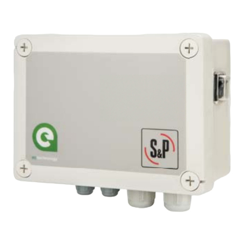
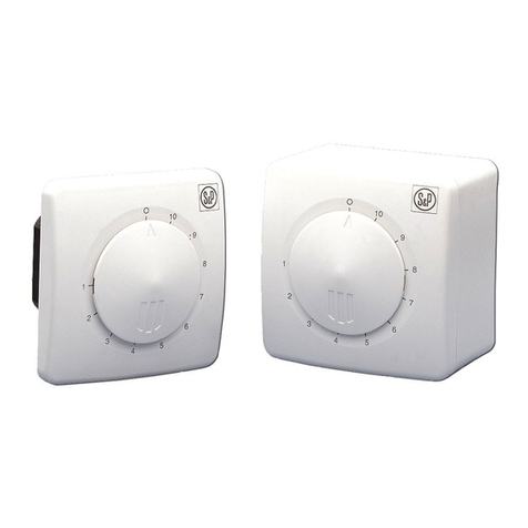
S&P CONTROL ECOWATT User manual

CONTROL ECOWATT

2
ESPAÑOL

3
ESPAÑOL

4
ESPAÑOL
El CONTROL ECOWATT AC/DC dispone de salida analógica y puede controlar un ventilador
maestro y un ventilador esclavo.

5
ESPAÑOL

6
ESPAÑOL

7
ESPAÑOL

8
ESPAÑOL

9
ESPAÑOL

10
ESPAÑOL

11
ESPAÑOL

12
ENGLISH
CONTROL ECOWAT AC/DC
}
}
}
}
}
}
}
}
}
}
+V
IN
GND
+V
IN
GND
+V
IN
GND
OUT
GND
OUT
GND
L
N
Analogical
input
0-10V/4-20mA
S1
Analogical
input
0-10V/4-20mA
S2
Analogical
input S3
0-10V/4-20mA
“Slave” output
0-10V
“Master” output
0-10V
“Hall”
input
Digital
input E3
Digital
input E1
Digital
input E2
Main supply
90-230V 50/60Hz

13
ENGLISH
CONTROL ECOWAT AC/4A
}
}
}
}
}
}
}
}
+V
IN
GND
+V
IN
GND
+V
IN
GND
OUT
GND
OUT
GND
}
L
N
Single phase
motor output
230V 50Hz
}
L
N
Analogical
input
0-10V/4-20mA
S1
Analogical
input
0-10V/4-20mA
S2
Analogical
input S3
0-10V/4-20mA
“Slave” output
0-10V
“Master” output
0-10V
Digital
input E3
Digital
input E1
Digital
input E2
Main supply
230V 50Hz

14
ENGLISH
DESCRIPTION
The range includes three models differentiated by input and motor output:
- CONTROL ECOWATT AC/DC: model with AC input and 0-10V analogical output for DC
motors or frequency converters (Fig.1).
- CONTROL ECOWATT AC/4A: model with single-phase AC input and voltage output for
single-phase motors up to 4A. With this model, 0-10V analogical outputs for DC motors
or frequency converters are also active (Fig.2).
Each model has three function modes:
- Proportional Integral control (PI) with analogical input (0-10V / 4-20mA)
- Control with three analogical inputs (0-10V / 4-20mA)
- Control with three digital inputs
CONTROL ECOWATT AC/DC incorporates an analogical output and can control both master and
slave fans.
INSTALLATION
Workshop assembly by authorised technicians
Fix to vertical wall with cable glands facing down, leave space around the fixture for evacuation
of thermal losses.
POWER SUPPLY
CONTROL ECOWATT AC/DC: 90 - 260VAC – 50/60Hz
CONTROL ECOWATT AC/4A: 230VAC + earth – 50Hz
FRONT PANEL AND FUNCTION SETTINGS
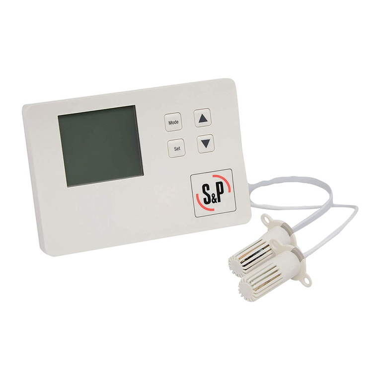
Digital display where the first line shows input values measured by sensors and output values
given as a % of the range of speeds.
The lower line indicates adjustment values (if no adjustments are made, the factory settings are
shown).
S1: 50% PR-OUT :40%
P1: 70%
S2: 1200% PR-OUT: 80%
P2: 1000 PPM
S3: 25% PR-OUT :100%
P3: 22°C
S1, S2 or S3:
Values measured by the sensors
- S1 relative humidity level in HR% (signal 0-10V)
- S2 concentration in PPM of CO2 (signal 4-20mA)
- S3 temperature in ºC (signal 0-10V)

15
ENGLISH
PR-OUT:
- % of 0-10V output for CONTROL ECOWATT AC/DC
- % of range of voltage adjustment for AC/4A CONTROL ECOWATT
P1, P2 or P3:
Settings at the average point of the selected range of functioning adjusted to the premises
where the sensor is installed..
Four adjustment keys:
- Sand Tkeys for changing the menus
- -and +keys for changing the settings
LED indicating input signal for sensors S1, S2 and S3
LED indicating output signal or output voltage level (according to model)
Green LED “POWER ON” that indicates that the CONTROL ECOWATT is switched on.
Red LED “ERROR” that indicates a CONTROL ECOWATT function error.
SETTINGS
All models in the CONTROL ECOWATT range have three function modes:
PI
PROPORTIONAL INTEGRAL
PROPORTIONAL
MINI MAXI
Changing the function settings
- After switching on the CONTROL ECOWATT, press one of the four keys on the front
panel (within 10s).
- Press the keys – o + to change function mode (factory setting: PROPORTIONAL
INTEGRAL )
“PROPORTIONAL INTEGRAL” mode
In this mode, the CONTROL ECOWATT is set up to function in a constant pressure system so a
single input value is possible, the Pascal set point value that we want to maintain in the duct
network. Only the S1 input may be used, connected to a TDP-type pressure transmitter.
S1: 150% PR-OUT: 50%
P1: 150 Pa
Output
Input
P
MAX output
Speed
range
MIN output

16
ENGLISH
To change the set point and the variables set in factory:
- Press any of the 4 keys on the front panel.
- The words “Set Point” appear on the display. Use the keys -or +to change setting
(factory setting: 150Pa)
S1: 60 PR-OUT: 80%
Set Point: 150
- Press the key pto move to the next parameter: “Range”. This parameter allows entry to
the bottom of the pressure sensor scale. Use the keys -or +to change setting (factory
setting: 0 – 300Pa)
S1: 60 PR-OUT: 80%
Range: 0-50
- Press the key pto move to the next parameter: “Kp”. This parameter allows modification
of motor response by means of changes in network pressure It is advisable to not
change the settings. Use the keys -or +to change setting (factory setting: 1000)
S1: 60 PR-OUT: 80%
Kp: 1000
- Press the key pto move to the next parameter: “Ki”. This parameter allows modification
of motor response by means of changes in network pressure It is advisable to not
change the settings. Use the keys -or +to change setting (factory setting: 100)
S1: 60 PR-OUT: 80%
Ki: 100
“PROPORTIONAL” mode
In this mode, the CONTROL ECOWATT is set up to work with one, two or three analogical
inputs (J6, J7 or J8), 4-20mA or 0-10V. The CONTROL ECOWATT functions in accordance
with the parameter of maximum demand. The sensors are connected in the inputs S1(J6),
S2(J7) and S3(J8). Depending on the type of sensor (4-20mA or 0-10V) set the micro switch
fitted in the circuit board to “mA” or “V”.
MAX output
Output
INmin INmax Input
Useful sensor range
(IN (+/-))
P
Speed
range
MIN output

17
ENGLISH
To change input settings from factory settings:
- Press any of the 4 keys on the front panel.
- “IN1 Type” appears on the display. This parameter allows the selection of the measure
unit for the channel 1 (sensor 1). The admitted measure units are:
o“OFF” to inactivate the channel when any sensor is connected.
o“%(V)” relative humidity sensor (RH%) connected to channel 1 with 0-10Vdc output .
o“%(mA)” relative humidity sensor (RH%) connected to channel 1 with 4-20mA output.
o“CO2(V)” CO2 sensor (PPM) connected to channel 1 with 0-10Vdc output.
o“CO2(mA)” CO2 sensor (PPM) connected to channel 1 with 4-20mA output
o“TEMP(V)” Temperature sensor (ºC) connected to channel 1 with 0-10Vdc output.
o“TEMP(mA)” Temperature sensor (ºC) connected to channel 1 with 4-20mA output.
Factory setting for IN1 Type = %RH(V)
S1: 60 PR-OUT: 80%
IN1 Type: %HR
- Press the key pto move to the next parameter: “IN1 RANGE”. This parameter allows
entry the pressure sensor range. Use the keys - or +to change setting (factory setting:
S1= 0-100 %HR)
S1: 60 PR-OUT: 80%
IN1 RANGE: 0-100%HR
- Press the key pto move to the next parameter: “IN1 SET” This parameter allows setting
the average value of the sensor range. Use the keys - or +to change setting (factory
setting: 70%HR)
S1: 60 PR-OUT: 80%
IN1 SET: 70%HR
- Press the key pto move to the next parameter: “IN (+/-)”. This parameter allows
adjustment of the width setting range of the sensor. Use the keys - or +to change
setting (factory setting: 40%HR)
S1: 60 PR-OUT: 80%
IN (+/-): 40
- Press the key pto move to the next parameter: “S1 ALARM”. This parameter allows an
alarm message to be sent when the average sensor value reaches a set percentage of
the average range value. (factory setting: 90%)
S1: 60 PR-OUT: 80%
S1 ALARM: 90%

18
ENGLISH
- Press the key pto move to the next sensor “IN2 Type” and follow the adjustment
procedure of the first sensor
Los valores de fabrica de las sondas 2 y 3 son los siguientes:
SENSOR 2 SENSOR 3
IN2 Type=CO2(mA) IN3 Type=TEMP(V)
IN2 RANGE=2000PPM IN3 RANGE=50ºC
IN2 SET=1000PPM IN3 SET=27ºC
IN2(+/-)=1000PPM IN3(+/-)=5ºC
S2 ALARM=90%(PPM) S3 ALARM=90%(ºC)
“MINI/MAXI” mode
In this mode, the CONTROL ECOWATT is set up to work with one, two or three contacts (J12,
J13 and J14) of the normally open (NO) or normally closed (NC) type. The CONTROL
ECOWATT functions in accordance with the first input that changes the setting and moves to
maximum speed. The sensors or external contacts are connected in the inputs E1(J12),
E2(J13) and E3(J14).
To change contact setting
- Press any of the 4 keys on the front panel.
- “IN1 OFF (NO)” appears on the display. This parameter indicates that the contact is in its
normal open position. Use keys - o +to change to NC (factory setting: NO)
- Press the key to pmove to the next inputs “IN2” and “IN3” and follow the same
procedure for each input. (factory setting: EN2: OFF(NO) – EN3:OFF(NO)).
CONTROL ECOWATT resetting
- Press the keys -and +simultaneously during 5 seconds until “RESET” appears on the
display, which allow to load all the factory setting values.
Restore defaults
& Reset? NO
- Press the key +to confirm the resetting operation for all the variables.
Restore defaults
& Reset? YES
This resetting operation needs a two-confirmation operation before to be acheived .
Press the key pto confirm the reset operation.
Output
input
P
MAX output
MIN output
Maximum speed
Minimum speed

19
ENGLISH
Changing output settings
To change the output settings that were set in the factory (applicable to the three modes):
- Press the keys simultaneously pand quntil the first parameter "MIN-OUTPUT”
appears on the display. This parameter allows adjustment of the minimum output setting
to between 0 and 50%. (factory setting: 10%)
S1: 60 PR-OUT: 80%
MIN-OUTPUT: 10%
- Press the key pto move to the next parameter: “MAX – OUTPUT”. This parameter
allows adjustment of the maximum output setting between 50 and 100%. (factory setting:
100%) – Output to terminals 10 and 11 of the J9 terminal.
S1: 60 PR-OUT: 80%
MAX-OUTPUT: 100%
- Press the key pto move to the next parameter: “Slave – OUT”. This parameter allows
adjustment of the maximum output setting between 50 and 150% of the second ventilator
controlled by the CONTROL ECOWATT. (factory setting: 100%) – Output to terminals
12 and 13 of the J10 terminal.
-
S1: 60 PR-OUT: 80%
Slave-OUT: 100%
- Press the key pto move to the next parameter: “Hall pulses”. With this parameter the
display displays the RPM speed of a motor fitted with a pulse per turn control. (factory
setting: 0 – no effect) – Output to terminal 14 and 15 of the J11 terminal.
S1: 60 PR-OUT: 80%
Hall pulses: 0
With the CONTROL ECOWATT AC/4A model, minimum voltage can be set between 80V and
150V, by means of the micro-switches (factory setting: 80V):
1 2 3 Vmin
0 0 0 80
0 0 1 90
0 1 0 100
0 1 1 110
1 0 0 120
1 0 1 130
1 1 0 140
1 1 1 150
ON=0

20
ENGLISH
}
Alarm relay
output 2
}
Alarm relay
output 1
Adjustment values
Inputs:
Sensor Unit Scale Set point Proportional band
Min. Max. Increase Factory setting Increase Factory setting Increase Factory setting
Pressure Pa 0 2500 50 300 10 150 --- ---
%HR % 0 100 10 100 5 70 5 40
CO2 ppm 0 2000 100 2000 100 1000 100 1000
Temp. ºC 0 50 5 50 1 22 1 5
Outputs:
Unit Min. Max. Increase Factory settings
Minimum speed (OUT MIN) RPM 0% 50% 5% 10%
Maximum speed (OUT MAX) RPM 50% 100% 5% 100%
Alarms:
Min. Max. Increase Factory settings
S1 ALARM 0% 100% 5% 90% 0,9 x 100 = 90%HR
S2 ALARM 0% 100% 5% 90% 0,9 x 2000 = 1800 ppm
S3 ALARM 0% 100% 5% 90% 0,9 x 50 = 45%HR
LED ERROR - OUTPUT RELAYS
CONTROL ECOWATT models include an LED "ERROR" on the front panel and in the circuit of
the two relays RL1 and RL2. They have the following functions:
The function of relay 1 (J13) is Alarm or Error, together with the LED “ERROR”.
Activation:
1. When all the sensors read 0 for 2s. The J13 relay is locked and the LED “ERROR” is lit.
“S1 ERROR” appears on the display.
If this happens, check the sensor connections that show "error" on the display.
2. In the PROPORTIONAL setting, when the alarm sensor limits are exceeded (S1 ALARM,
S2 ALARM, S3 ALARM). The LED “ERROR” flashes twice. “S1 ALARM” appears on the
display.
The function of relay 2 (J5), in the MIN-MAX setting, is to activate the high speed of a two-
speed motor (2-windings single phase motor) when there is a change of input
Other manuals for CONTROL ECOWATT
1
This manual suits for next models
2
Table of contents
Languages:
Other S&P Controllers manuals
Popular Controllers manuals by other brands

Rain Bird
Rain Bird ESP-RZ Installation guide & operation manual

Controlli
Controlli MVE5 Series Mounting instructions

Magtrol
Magtrol DSP7000 user manual

Ascon tecnologic
Ascon tecnologic KM3-L Engineering manual

TechGrow
TechGrow Clima Micro Plus Min/Max Fan Speed user manual

FRTek
FRTek ELITE NEXT quick guide

Samson
Samson 3374 Mounting and operating instructions
Meccanica Fadini
Meccanica Fadini HELIOS 29 quick start guide

Epever
Epever LandStar GPLI Series quick guide

Carson
Carson SPEED 11T operating instructions

Plum
Plum ecoMAX810P3-L TOUCH Service and assembly manual

Carlisle
Carlisle BINKS 85-435 Service manual