manuals.online logo
Brands
  1. Home
  2. •
  3. Brands
  4. •
  5. S&P
  6. •
  7. Controllers
  8. •
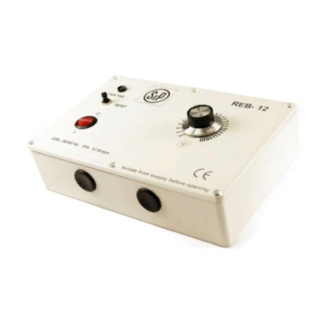
  9. S&P REB 5 User manual

S&P REB 5 User manual

11
22
33
44
55
66
77
88
11
66
88
66
5
5
22
22
- Voltaje 230V 50Hz
- Intensidad máx. 5A
- Intensidad mínima a regular 0,8A
- Control por potenciómetro
- Regulación de máximo a mínimo
- Interruptor luminoso
- Conexionado por regletas
- Ajuste de la velocidad mínima
- Ajuste de la velocidad máxima
- Caja estanca IP 54
- Filtro EMC según EN55014
- Protección por fusible HF de 5A
- Switch selección arranque pulso inicial (SW1-1).
- Inicio mediante rampa de aceleración seleccionable (SW1-2).
- Dimensiones (mm) 164x96x85
- Voltage 230V 50Hz
- Max. current 5A
- Minimum load 0,8A
- Control by potentiometer
- Regulation from max to min
- Switch with indicator lamp
- Connection by terminals
- Minimum speed adjustable
- Maximum speed adjustable
- Enclosure IP54
- EMC filter according to EN55014 standard
- Fuse protection HF 5A
- Switch for kick start selection (SW1-1)
- Start with selectable acceleration ramp (SW1-2)
- Dimensions (mm) 164x96x85
- Tornillos sujeción tapa
- Botón potenciómetro
- Prensaestopas entrada cables
- Fijación regulador
- Regletas conexión
- Interruptor luminoso
- Fusible
- Ajuste velocidad mínima
- Ajuste velocidad máxima
- Conector potenciometro
- Switch selección arranque pulso inicial
- Switch selección rampa aceleración
- Hold cover screw
- Button
- Input wires
- Clamping holes
- Connection terminal
- Switch with indicator lamp
- Fuse
- Minimum speed adjustment
- Maximum speed adjustment
- Connector potentiometer
- Switch for kick start selection
- Switch for acceleration ramp selection
Para el correcto funcionamiento del regulador se recomienda seguir
estrictamente las siguientes instrucciones:
2 - Situar el interruptor en posición de parado.
3 - Conectar la toma de tierra, los ventiladores y la línea de 230V a
la regleta según esquema adjunto.
4 - Situar el interruptor en la posición de marcha y ajustar la
velocidad mínima mediante y la velocidad máxima mediante .
IMPORTANTE: Es conveniente que el voltaje sobre
el motor no sea inferior a 80V.
(S&P Se reserva el derecho a modificaciones sin previo aviso.) (S&P reserves the right to make changes without notice).
5 - Tapar la caja y comprobar el correcto funcionamiento
del regulador mediante el potenciómetro .
DATOS TÉCNICOS TECHNICAL DATA
INSTRUCCIONES DE MONTAJE MOUNTING INSTRUCTIONS
ATENCIÓN ATTENTION
- Situar el regulador según se muestra en la figura adjunta.
- Es imprescindible conectar la línea de tierra al regulador.
- S&P no se responsabiliza de los daños causados por una instalación
defectuosa del regulador.
La línea de alimentación del regulador y la salida hacia los ventiladores
deben tener la sección adecuada para la intensidad máxima del
regulador, y la instalación en general debe cumplir las normativas
vigentes.
- The operating position must be as shown below.
- It´s essential to connect the earth line to the regulator.
- S&P don't assumes the damages due a faulty installation of the
regulator.
- The main line of regulator and the output to the fans must have
the suitable section by the maximum current of the regulator and
the installation mainly has to comply with the actual safety
standards.
OPERATING POSITION
CONNECTION DIAGRAM
POSICIÓN DE FUNCIONAMIENTO
DIAGRAMA DE CONEXIÓN
LL1
230V MOTOR
N
FUS
The under detailed rules must be strictly followed for the
correct use of the equipment:
1 - Take off the box cover loosening the screws (it is
not necessary to take off the button ). Attention: the
potentiometer is connected, by means of three wires,
to the base of the regulator.
2 - Put the switch in OFF position.
3 - Connect the earth, the fans and 230V line to terminal
according to the included scheme.
4 - Put the switch in the ON position and adjust the
minimum speed by means of and maximum speed by
means of .
IMPORTANT : In case of regulating motors it´s nece-
ssary to have a minimum speed of 80V.
5 - Close the box, and verify that it works fine with the
potentiometer .
1 - Abrir la tapa aflojando los 4 tornillos (no hace falta quitar el
boton del potenciómetro ) teniendo en cuenta que el poten-
ciómetro está conectado, mediante tres cablecillos, a la base
del regulador.
N
99
NOTA NOTE
RV01
10
11
9
SI/YES NO NO
11
10
11
11
9
12 12
OFF
ON
1
8
2
10
6
7
4
4
3
5
OFF
ON
11
9
12
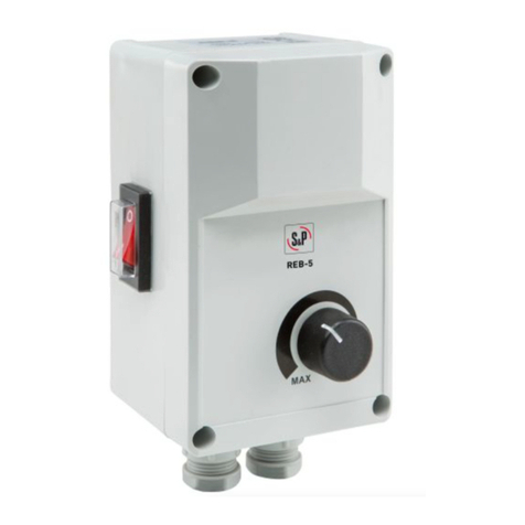
REB-5
REGULADOR DE VELOCIDAD
PARA MOTORES MONOFÁSICOS
SINGLE-PHASE SPEED CONTROLLER
Pol. Industrial Llevant
C/ Llevant, 4
08150 Parets del Vallés (Barcelona)
España / Spain
Soler & Palau Tel. 93 571 93 00
Fax. 93 571 93 01
Tel. Int. +34 93 571 93 00
Fax Int. + 34 93 571 93 11
[email protected]
www.solerpalau.com
REB-5
MIN
MAX
SW1-1: Este regulador incorpora, si se selecciona , un nuevo
sistema de protección con arranque de pulso inicial:
Cuando se conecta el regulador, el motor funciona al
100% durante 10 segundos aproximadamente, esto
se repite cada vez que se para y se conecta el regulador.
SW1-2: Este regulador incorpora, si se selecciona , una rampa
de aceleración (aprox. 10s de 0 a 100%) cuando se conecta
el regulador.
12
SW1-2: This regulator, if selected , has an acceleration ramp
(aprox. 10s from 0 to 100%).
12
SW1-1: This regulator incorporates, if selected , the new
system protection with kick start:
When the regulator is connected, the motor works at
100% during 10 seconds about, this function is repeat
each stop and when connected the regulator.
Tłumaczenie instrukcji oryginalnej (z języka angielskiego)
JEDNOFAZOWY REGULATOR PRĘDKOŚCI REB-5
DANE TECHNICZNE
-Napiecie 230V 50 z
-Obciążenie maksymalne 5A
-Obciażenie minimalne 0,8A
-Regulacja przy pomocy potencjometru
-Regulacja od max do min
-Przełącznik z lampka kontrolną
-Podłączenie poprzez zaciski
-Regulowana minimalna prędkość
-Regulowana maksymalna prędkość
-Obudowa IP 54
-Filtr EMC zgodnie z normą EN55014
-Bezpiecznik F 5A
-Przełącznik do wyboru rozruchu bezpośredniego (SW1-1)
-Przełącznik do wyboru rozruchu z rampą przyspieszenia (SW1-2)
-Wymairy (mm) 164x96x85
1 – element łączny pokrywy
2 – Nastawnik
3 – Wejście na przewody
4 – Otwory mocujące
5 - Listwa przyłączeniowa
6 – Przełącznik z lampką kontrolną
7 – Bezpiecznik
8 - Regulowana minimalna prędkość
9 - Regulowana maksymalna prędkość
10 – przyłącze potencjometru
11 – przełączik do wyboru rozruchu bezpośrendiego
12 - przełącznik do wyboru rozruchu z rampą przyspieszenia
INSTURKCJA MONTAŻU
Ponizsze wytyczne muszą być ścisle przestrzegane w celu właściwego użycia urządzenia:
1 – Zdejmij pokrywę urządzenia po zwolnieniu elementów mocujących (1). Nie jest konieczny demontaż nastawnika (2). Uwaga: potencjometr
(nastawnik) jest połączony z podstawą regulatora poprzez trzy przewody.
2 – Ustaw przełącznik (6) w pozycji OFF.
3 – Podłącz uziemienie, wentylator oraz zasilanie 230V do listwy (5) zgodnie z załączonym schematem.
4 – Ustaw przełącznik (6) w pozycji ON oraz ustaw prędkość minimalną przy pomocy elementu (8) oraz maksymalną predkość przy pomocy
elelementu (9)
WAŻNE: W przypadku regulacji silnika, minimalne napięcie nie może być niższe niż 80V.
5 – Zamknij urządzenie oraz upewnij się, ze działa sprawnie z potencjometrem (2).
UWAGA
SW1-1: Ten przełącznik (jeżeli wybrano 11) uruchamia zabezpieczenie powodujące bezpośredni rozruch silnika. Gdy regulator jest włączony
silnik działa z prędkością 100% przez czas ok. 10 sekund. Funkcja ta jest powtarzana przy każdym zatrzymaniu oraz włączeniu regulatora.
SW1-2. Ten przełącznik (jeżeli wybrano 12) uruchamia tryb rozruchu z rampą przyspieszenia (w przybliżeniu – rozruch w czasie 10s – od 0% do
100% prędkości).
UWAGA
- Urządzenie może pracować jedynie w pozycji pokazanej poniżej
- Niezbędne jest podłączenie linii uziemienia do regulatora
- S&P nie odpowiada za szkodzy powstałe w wyniku nieprawidłowej instalacji regulatora
- Zasilanie regulatora oraz wyjście do wentylatora muszą zostać dobrane na podstawie maksymalnego prądu regulatora, a instalacja musi
spełniać aktualne normy dotyczące bezpieczeństwa.
(S&P zastrzega prawo do zmian w ninijeszym dokumencie bez obwiązku powiadamania uzytkownika)
SC EMAT PODŁĄCZENIA
POZYCJA PRACY
TAK
NIE
NIE
MOTOR
–
silnik
FUS - bezpiecznik

Other manuals for REB 5

2

Other S&P Controllers manuals

S&P REB-1NE User manual

S&P

S&P REB-1NE User manual

S&P CONTROL ECOWATT User manual

S&P

S&P CONTROL ECOWATT User manual

S&P REB 5 User manual

S&P

S&P REB 5 User manual

S&P RMB User manual

S&P

S&P RMB User manual

S&P CONTROL ECOWATT User manual

S&P

S&P CONTROL ECOWATT User manual

S&P RMB Series User manual

S&P

S&P RMB Series User manual

S&P RMT-1.5 User manual

S&P

S&P RMT-1.5 User manual

S&P ES24V User manual

S&P

S&P ES24V User manual

S&P MULTI-REG CONTROL 2841 Series User manual

S&P

S&P MULTI-REG CONTROL 2841 Series User manual

S&P RMB Series User manual

S&P

S&P RMB Series User manual

S&P Envirosense ES24V User manual

S&P

S&P Envirosense ES24V User manual

S&P TR90 Series User manual

S&P

S&P TR90 Series User manual

S&P REB-1N User manual

S&P

S&P REB-1N User manual

S&P REB-1N User manual

S&P

S&P REB-1N User manual

S&P REB 5 User manual

S&P

S&P REB 5 User manual

Popular Controllers manuals by other brands

HomeMatic HMW-LC-Sw2-DR Installation and operating manual

HomeMatic

HomeMatic HMW-LC-Sw2-DR Installation and operating manual

Gotting HG G-73650ZD Basics, Setup and Software

Gotting

Gotting HG G-73650ZD Basics, Setup and Software

FIBER SENSYS Fiber Defender FD508 user manual

FIBER SENSYS

FIBER SENSYS Fiber Defender FD508 user manual

Dynamite DYN3810 instruction manual

Dynamite

Dynamite DYN3810 instruction manual

THORLABS IP500 user guide

THORLABS

THORLABS IP500 user guide

tbs electronics Omnicharge Solar OCS 150-60 owner's manual

tbs electronics

tbs electronics Omnicharge Solar OCS 150-60 owner's manual

Sistemes Electrònics Progrés s.a. AGRONIC 2500 instruction manual

Sistemes Electrònics Progrés s.a.

Sistemes Electrònics Progrés s.a. AGRONIC 2500 instruction manual

Grandstream Networks HA100 user manual

Grandstream Networks

Grandstream Networks HA100 user manual

Wilo HiControl 1 Installation and operating instructions

Wilo

Wilo HiControl 1 Installation and operating instructions

Texas Instruments TMS320DM646x user guide

Texas Instruments

Texas Instruments TMS320DM646x user guide

K-BUS ARSA-04/16.S user manual

K-BUS

K-BUS ARSA-04/16.S user manual

Christie TVC-1211 user manual

Christie

Christie TVC-1211 user manual

Smartgen HAT530 user manual

Smartgen

Smartgen HAT530 user manual

Voicebird Voicebird Mini user guide

Voicebird

Voicebird Voicebird Mini user guide

SpeedyBee F7 35A BLS Mini Stack user manual

SpeedyBee

SpeedyBee F7 35A BLS Mini Stack user manual

Uponor Smatrix Base Pro Quick guides

Uponor

Uponor Smatrix Base Pro Quick guides

Toshiba RBC-ASC11E installation manual

Toshiba

Toshiba RBC-ASC11E installation manual

METRON FD4 manual

METRON

METRON FD4 manual

manuals.online logo
manuals.online logoBrands
  • About & Mission
  • Contact us
  • Privacy Policy
  • Terms and Conditions

Copyright 2025 Manuals.Online. All Rights Reserved.