ERV TRC500
1.800.961.7370 INSTALLATION, OPERATION AND MAINTENANCE MANUAL WWW.SOLERPALAU-USA.COM8
INSTALLATION
1. Before servicing or cleaning the unit, switch
power off at disconnect switch or service pan-
el and lock-out/tag-out to prevent power from
being switched on accidentally. More than one
disconnect switch may be required to de-ener-
gize the equipment for servicing.
2. This installation manual shows the suggested
installation method. Additional measures may be
required by local codes and standards.
3. Installation work and electrical wiring must be
done by qualified professional(s) in accordance
with all applicable codes, standards and licens-
ing requirements.
4. Any structural alterations necessary for instal-
lation must comply with all applicable building,
health, and safety code requirements.
5. This unit must be grounded.
6. Sufficient air is needed for proper combus-
tion and exhausting of gases through the flue
(chimney) of fuel burning equipment that might be
installed in the area affected by this equipment.
If this unit is exhausting air from a space in
which chimney-vented fuel burning equipment is
located, take steps to assure that combustion
air supply is not affected. Follow the heating
equipment manufacturer’s requirements and the
combustion air supply requirements of applica-
ble codes and standards.
7. Use the unit only in the manner intended by the
manufacturer. If you have questions, contact the
manufacturer.
8. This unit is intended for general ventilating only.
Do not use to exhaust hazardous or explosive
materials and vapors. Do not connect this unit to
range hoods, fume hoods or collection systems
for toxics.
9. When cutting or drilling into wall or ceiling, do
not damage electrical wiring and other hidden
utilities.
10. This unit must be properly ducted to the out-
doors.
RISK OF FIRE, ELECTRIC SHOCK, OR INJURY. OBSERVE ALL CODES AND THE FOLLOWING:
WARNING
Take these simple steps to attenuate noise from the unit.
OUTSIDE THE BUILDING
Exhaust velocity noise is the primary cause of unit-
related noise outside the building. Size the exhaust
duct and grille for less than 1000 fpm air velocity.
When practical, orient the exhaust air hood to point
away from houses or public areas.
DUCTS
Make sure the ductwork at the unit outlets is stiff
enough to resist the flexure and resulting booming
associated with system start-up and shut-off, as well
as the turbulent flow conditions at the blower outlets.
In general, provide smooth transitions from the ERV’s
outlets to the duct. The ducts connecting to the
outlets should be straight for a sufficient distance,
with gradual transitions to the final duct size.
These guidelines are consistent with SMACNA
recommended duct layout practices for efficient
and quiet air movement. Follow SMACNA
guidelines.
RADIATED NOISE
The outlet ducts can be significant sources of
radiated sound as well. The FA and EA ducts (outlet
ducts) should be insulated for sound control. This
insulation should start at the unit. At a minimum the
first ten feet of duct should be insulated. All parts
of the FA and EA ducts located in the mechanical
space should be insulated for sound control, both to
minimize sound radiation out of these ducts and also
to control sound radiation into the ducts.
AERODYNAMIC (VELOCITY) NOISE
When sound attenuation is a design concern, the
primary consideration is velocity noise at the unit’s
Fresh Air blower outlet. The average velocity at
the blower outlets is 1100 FPM when the unit is
operating at 600 CFM.
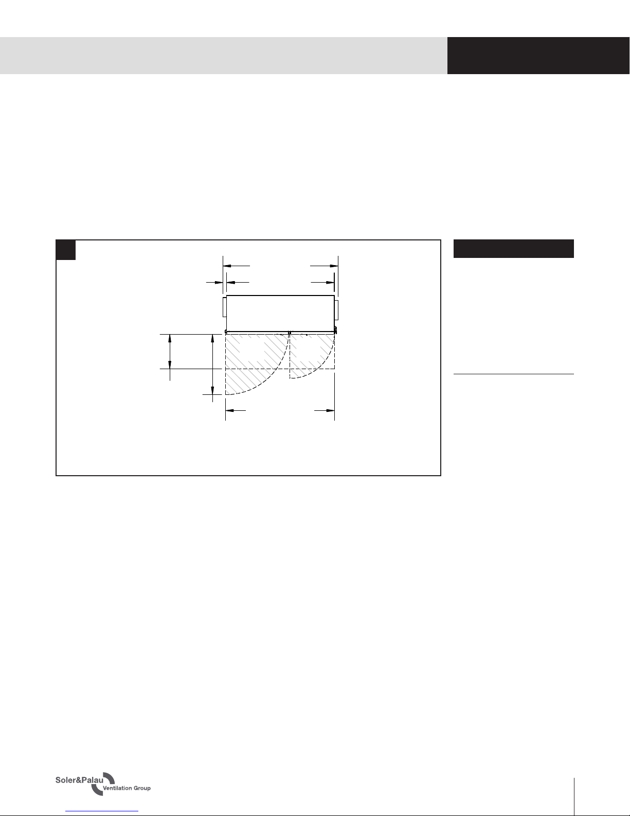
SOUND ATTENUATION
PLANNING
YOUR INSTALLATION