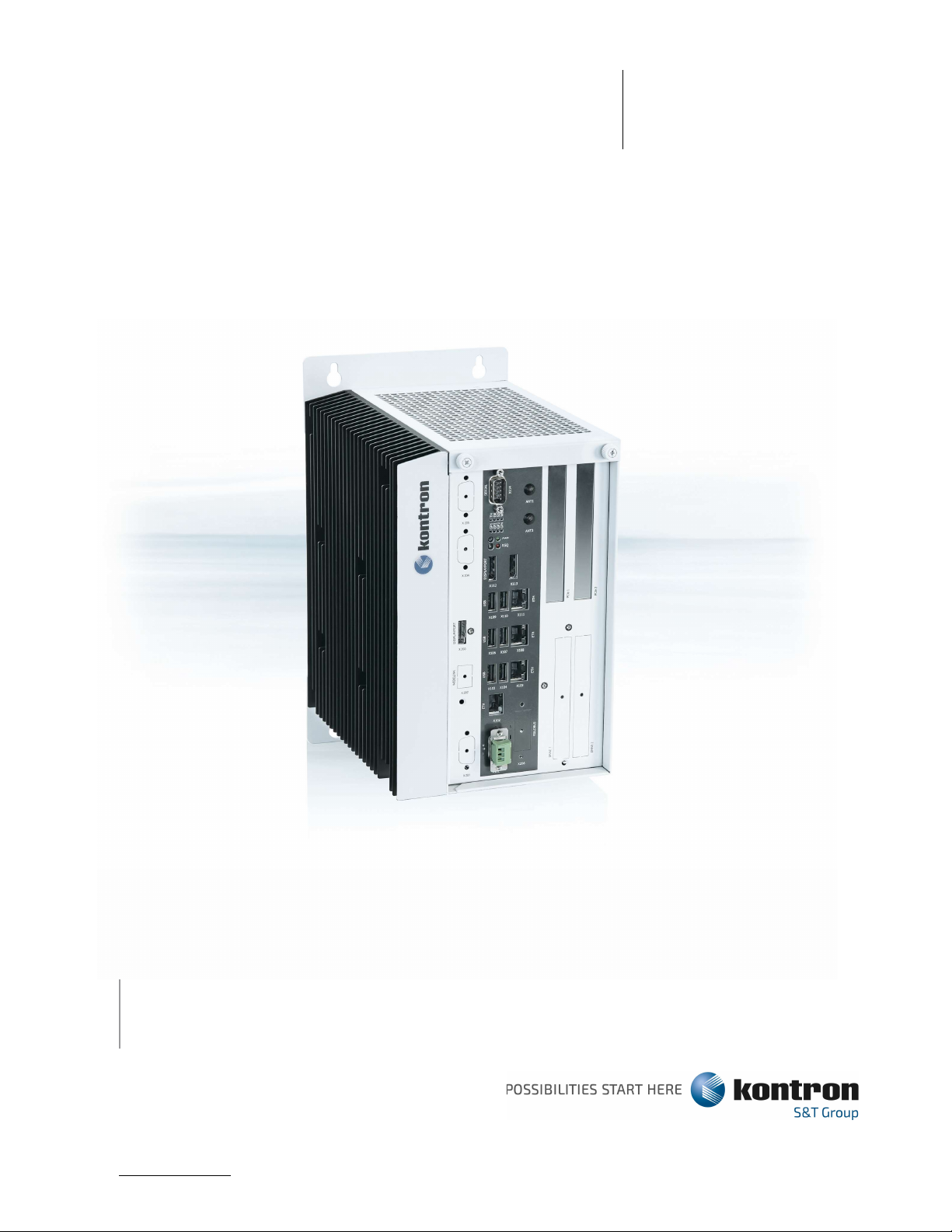
S&T KBOX C-103-NGSF User manual
USER GUIDE
www.kontron.com // 1
,
KBox C-103-NGSF
User Guide, Rev. Proof of Concept
KBOX C-103-NGSF - USER GUIDE

KBox C-103-NGSF - User Guide, Rev. Proof of Concept
www.kontron.com // 2
This page has been intentionally left blank

KBox C-103-NGSF - User Guide, Rev. Proof of Concept
www.kontron.com // 3
Disclaimer
Kontron would like to point out that the information contained in this user guide may be
subject to alteration, particularly as a result of the constant upgrading of Kontron
products. This document does not entail any guarantee on the part of Kontron with respect
to technical processes described in the user guide or any product characteristics set out
in the user guide. Kontron assumes no responsibility or liability for the use of the
described product(s), conveys no license or title under any patent, copyright or mask
work rights to these products and makes no representations or warranties that these
products are free from patent, copyright or mask work right infringement unless otherwise
specified. Applications that are described in this user guide are for illustration purposes
only. Kontron makes no representation or warranty that such application will be suitable
for the specified use without further testing or modification. Kontron expressly informs
the user that this user guide only contains a general description of processes and
instructions which may not be applicable in every individual case. In cases of doubt,
please contact Kontron.
This user guide is protected by copyright. All rights are reserved by Kontron. No part of
this document may be reproduced, transmitted, transcribed, stored in a retrieval system,
or translated into any language or computer language, in any form or by any means
(electronic, mechanical, photocopying, recording, or otherwise), without the express
written permission of Kontron. Kontron points out that the information contained in this
user guide is constantly being updated in line with the technical alterations and
improvements made by Kontron to the products and thus this user guide only reflects the
technical status of the products by Kontron at the time of publishing.
Brand and product names are trademarks or registered trademarks of their respective owners.
©2021 by Kontron Europe GmbH
Kontron Europe GmbH
Gutenbergstraße 2
85737 Ismaning
Germany
www.kontron.com

KBox C-103-NGSF - User Guide, Rev. Proof of Concept
www.kontron.com // 4
High Risk Applications Hazard Notice
THIS DEVICE AND ASSOCIATED SOFTWARE ARE NOT DESIGNED, MANUFACTURED OR INTENDED
FOR USE OR RESALE FOR THE OPERATION OF NUCLEAR FACILITIES, THE NAVIGATION,
CONTROL OR COMMUNICATION SYSTEMS FOR AIRCRAFT OR OTHER TRANSPORTATION, AIR
TRAFFIC CONTROL, LIFE SUPPORT OR LIFE SUSTAINING APPLICATIONS, WEAPONS SYSTEMS,
OR ANY OTHER APPLICATION IN A HAZARDOUS ENVIRONMENT, OR REQUIRING FAIL-SAFE
PERFORMANCE, OR IN WHICH THE FAILURE OF PRODUCTS COULD LEAD DIRECTLY TO DEATH,
PERSONAL INJURY, OR SEVERE PHYSICAL OR ENVIRONMENTAL DAMAGE (COLLECTIVELY,
"HIGH RISK APPLICATIONS").
You understand and agree that your use of Kontron devices as a component in High Risk
Applications is entirely at your risk. To minimize the risks associated with your
products and applications, you should provide adequate design and operating safeguards.
You are solely responsible for compliance with all legal, regulatory, safety, and
security related requirements concerning your products. You are responsible to ensure
that your systems (and any Kontron hardware or software components incorporated in your
systems) meet all applicable requirements. Unless otherwise stated in the product
documentation, the Kontron device is not provided with error-tolerance capabilities and
cannot therefore be deemed as being engineered, manufactured or setup to be compliant
for implementation or for resale as device in High Risk Applications. All application
and safety related information in this document (including application descriptions,
suggested safety measures, suggested Kontron products, and other materials) is provided
for reference only.
Handling and operation of the product is permitted only for trained personnel within a work
place that is access controlled. Please follow the “General Safety Instructions” supplied with the
system.
You find the most recent version of the “General Safety Instructions“ online in the download
area of this product.
KBox C-103-NGSF - User Guide, Rev. Proof of Concept
www.kontron.com // 5
Revision History
Revision Brief Description of Changes Date of Issue Author
/Edito
r
PRE Initial Issue 2021-May RP
Terms and Conditions
Kontron warrants products in accordance with defined regional warranty periods. For more information about warranty
compliance and conformity, and the warranty period in your region, visit http://www.kontron.com/terms-and-conditions.
Kontron sells products worldwide and declares regional General Terms & Conditions of Sale, and Purchase Order Terms
& Conditions. Visit http://www.kontron.com/terms-and-conditions.
For contact information, refer to the corporate offices contact information on the last page of this user guide or visit our
website CONTACT US.
Customer Support
Find Kontron contacts by visiting: https://www.kontron.de/support-and-services.
Customer Service
As a trusted technology innovator and global solutions provider, Kontron extends its
embedded market strengths into a services portfolio allowing companies to break the
barriers of traditional product lifecycles. Proven product expertise coupled with
collaborative and highly-experienced support enables Kontron to provide exceptional
peace of mind to build and maintain successful products.
For more details on Kontron’s service offerings such as: enhanced repair services,
extended warranty, Kontron training academy, and more visit
https://www.kontron.de/support-and-services.

KBox C-103-NGSF - User Guide, Rev. Proof of Concept
www.kontron.com // 6
Symbols
The following symbols may be used in this user guide
DANGER indicates a hazardous situation which, if not avoided,
will result in death or serious injury.
WARNING indicates a hazardous situation which, if not avoided,
could result in death or serious injury.
NOTICE indicates a property damage message.
CAUTION indicates a hazardous situation which, if not avoided,
may result in minor or moderate injury.
Electric Shock!
This symbol and title warn of hazards due to electrical shocks (> 60
V)
when touching products or parts of products
. Failure to observe the
precautions indicated and/or prescribed by the law may endanger your
life/health and/or result in damage to your material.
ESD Sensitive Device!
This symbol and title inform that the electronic boards and their
components are sensitive to static electricity. Care must therefore be
taken during all handling operations and inspections
of this product in
order to ensure product integrity at all times.
HOT Surface!
Do NOT touch! Allow to cool before servicing.
Laser!
This symbol inform of the risk of exposure to laser beam and light
emitting devices (LEDs) from an electrical de
vice. Eye protection per
manufacturer notice shall review before servicing.
This symbol indicates general information about the product and the
user guide.
This symbol also indicates detail information about the specific
product configuration.
This symbol precedes helpful hints and tips for daily use.

KBox C-103-NGSF - User Guide, Rev. Proof of Concept
www.kontron.com // 7

KBox C-103-NGSF – User Guide, Rev. Proof of Concept
www.kontron.com // 8
For Your Safety
Your new Kontron product was developed and tested carefully to provide all features
necessary to ensure its compliance with electrical safety requirements. It was also
designed for a long fault-free life. However, the life expectancy of your product can be
drastically reduced by improper treatment during unpacking and installation. Therefore,
in the interest of your own safety and of the correct operation of your new Kontron
product, you are requested to conform with the following guidelines.
High Voltage Safety Instructions
As a precaution and in case of danger, the power connector must be easily accessible.
The power connector is the product’s main disconnect device.
Warning
All operations on this product must be carried out by sufficiently skilled personnel only.
Electric Shock!
Before installing a non hot-swappable Kontron product into a system always ensure that your
mains power is switched off. This also applies to the installation of piggybacks. Serious
electrical shock hazards can exist during all installation, repair, and maintenance operations on
this product. Therefore, always unplug the power cable and any other cables which provide
external voltages before performing any work on this product.
Earth ground connection to vehicle’s chassis or a central grounding point shall remain
connected. The earth ground cable shall be the last cable to be disconnected or the first cable
to be connected when performing installation or removal procedures on this product.
Special Handling and Unpacking Instruction
ESD Sensitive Device!
Electronic boards and their components are sensitive to static electricity. Therefore, care must
be taken during all handling operations and inspections of this product, in order to ensure
product integrity at all times.
Do not handle this product out of its protective enclosure while it is not used for
operational purposes unless it is otherwise protected.
Whenever possible, unpack or pack this product only at EOS/ESD safe work stations. Where
a safe work station is not guaranteed, it is important for the user to be electrically
discharged before touching the product with his/her hands or tools. This is most easily
done by touching a metal part of your system housing.
It is particularly important to observe standard anti-static precautions when changing
piggybacks, ROM devices, jumper settings etc. If the product contains batteries for RTC
or memory backup, ensure that the product is not placed on conductive surfaces,
including anti-static plastics or sponges. They can cause short circuits and damage the
batteries or conductive circuits on the product.

KBox C-103-NGSF - User Guide, Rev. Proof of Concept
www.kontron.com // 9
Lithium Battery Precautions
If your product is equipped with a lithium battery, take the following precautions when
replacing the battery.
Danger of explosion if the battery is replaced incorrectly.
Replace only with same or equivalent battery type recommended by
the manufacturer.
Dispose of used batteries according to the manufacturer’s
instructions.
General Instructions on Usage
In order to maintain Kontron’s product warranty, this product must not be altered or modified in any way. Changes or
modifications to the product, that are not explicitly approved by Kontron and described in this user guide or received
from Kontron Support as a special handling instruction, will void your warranty.
This product should only be installed in or connected to systems that fulfill all necessary technical and specific
environmental requirements. This also applies to the operational temperature range of the specific board version that
must not be exceeded. If batteries are present, their temperature restrictions must be taken into account.
In performing all necessary installation and application operations, only follow the instructions supplied by the present
user guide.
Keep all the original packaging material for future storage or warranty shipments. If it is necessary to store or ship the
product then re-pack it in the same manner as it was delivered.
Special care is necessary when handling or unpacking the product. See Special Handling and Unpacking Instruction.
Quality and Environmental Management
Kontron aims to deliver reliable high-end products designed and built for quality, and
aims to complying with environmental laws, regulations, and other environmentally
oriented requirements. For more information regarding Kontron’s quality and
environmental responsibilities, visit http://www.kontron.com/about-kontron/corporate-
responsibility/quality-management.
Disposal and Recycling
Kontron’s products are manufactured to satisfy environmental protection requirements
where possible. Many of the components used are capable of being recycled. Final
disposal of this product after its service life must be accomplished in accordance with
applicable country, state, or local laws or regulations.
WEEE Compliance
The Waste Electrical and Electronic Equipment (WEEE) Directive aims to:
Reduce waste arising from electrical and electronic equipment (EEE)
Make producers of EEE responsible for the environmental impact of their products,
especially when the product become waste
Encourage separate collection and subsequent treatment, reuse, recovery, recycling
and sound environmental disposal of EEE
Improve the environmental performance of all those involved during the lifecycle of
EEE

KBox C-103-NGSF - User Guide, Rev. Proof of Concept
www.kontron.com // 10
Environmental protection is a high priority with Kontron.
Kontron follows the WEEE directive
You are encouraged to return our products for proper disposal.

KBox C-103-NGSF - User Guide, Rev. Proof of Concept
www.kontron.com // 11
Table of Contents
Symbols .............................................................................. 6
For Your Safety ...................................................................... 8
High Voltage Safety Instructions ..................................................... 8
Lithium Battery Precautions .......................................................... 9
General Instructions on Usage ........................................................ 9
Quality and Environmental Management ................................................. 9
Disposal and Recycling ............................................................... 9
WEEE Compliance ...................................................................... 9
Table of Contents ................................................................... 11
List of Tables ...................................................................... 14
List of Figures ..................................................................... 14
1/ General Safety Instructions ...................................................... 16
1.1. Electrostatic Discharge (ESD) .................................................. 19
1.1.1. Grounding Methods ............................................................ 19
1.2. Instructions for the optional Lithium Battery .................................. 19
2/ Shipment and Unpacking ........................................................... 20
2.1. Unpacking ...................................................................... 20
2.2. Scope of Delivery .............................................................. 20
2.2.1. Optional Parts (System Expansion) ............................................ 20
2.2.2. Optional System Extension .................................................... 20
2.3. Type Label and Product Identification .......................................... 20
3/ System Overview .................................................................. 22
3.1. Optional RTC Lithium Battery (internally-accessible) ........................... 23
3.2. System Expansion Capabilities .................................................. 23
3.2.1. M.2 Interfaces ............................................................... 23
3.2.2. Mini PCI Express® Interface .................................................. 23
3.2.3. Standard PCI Express® Interfaces ............................................. 23
3.2.4. SATA Interfaces .............................................................. 23
3.2.5. Internal USB 3.0 Interface ................................................... 24
3.2.6. Internal microSD Card and microSIM Card Interface ............................ 24
3.3. KBox C-103-NGSF Variant ........................................................ 26
3.3.1. X101/X201 – Power Input Connectors ........................................... 28
3.3.2. X102/X105/X108/X111 - Ethernet Connectors (ETH) .............................. 29
3.3.3. X103/X106/X109 - USB 3.0 ..................................................... 29
3.3.4. X104/X107/X110 - USB 2.0 ..................................................... 29
3.3.5. X112/X113/X203 - DisplayPorts ................................................ 30
3.3.6. X114 - RS232 Port ............................................................ 30
3.3.7. POWER Button and PWR LED ..................................................... 30
3.3.8. RESCUE Button and RSQ LED .................................................... 31
3.3.9. Status and General Purpose LEDs .............................................. 31
3.3.10. PCI/PCIe Expansion Slots .................................................... 32
3.3.11. Internal or Removable 2.5" SATA HDDs/SSDs ................................... 33
3.3.11.1. Installing/Removing the removable HDD/SSD ................................. 34
3.4. Left and Right Side View ....................................................... 35
3.5. Top and Bottom Side View ....................................................... 35
3.6. Rear Side View ................................................................. 36
3.7. Functional Earth Stud .......................................................... 36
4/ System Extensions ................................................................ 38
4.1. (X203) - 3rd DisplayPort ........................................................ 38

KBox C-103-NGSF - User Guide, Rev. Proof of Concept
www.kontron.com // 12
4.2. (X206) WiFi .................................................................... 38
4.2.1. WiFi/BT ...................................................................... 38
4.3. Optional Versions with Fan Tray - KBox C-103-NGSF .............................. 39
5/ Accessing Internal Components .................................................... 40
5.1. Top Cover ...................................................................... 41
5.2. Opening and Closing the KBox C-103-NGSF ........................................ 43
5.2.1. DIP Switch ................................................................... 46
5.2.2. Expansion Socket for PCIe Mini Cards ......................................... 46
5.2.3. Riser Cards Expansion Sockets for PCI/PCIe Cards ............................. 46
5.2.4. Installing/Removing an M.2 Module ............................................ 47
5.2.5. Installing/Removing a microSD/microSIM Card .................................. 48
6/ Power and Thermal Considerations ................................................. 49
6.1. System Power Portfolio ......................................................... 49
6.2. Convection Cooling ............................................................. 49
6.3. Active Cooling via the optional Fan Tray ....................................... 49
6.4. Minimum System Clearance ....................................................... 51
6.5. Third Party Components ......................................................... 51
6.6. Processor Thermal Monitoring ................................................... 51
6.7. Processor Thermal Trip Feature ................................................. 51
7/ Installation Instructions ........................................................ 52
7.1. Specifications of the internal M.2 Connectors .................................. 54
7.2. Control Cabinet Mounting ....................................................... 54
7.3. DC Power Plug Terminal ......................................................... 56
7.3.1. Cabling ...................................................................... 56
7.4. Side Wall Mounting (Option) .................................................... 57
8/ Starting Up ...................................................................... 58
8.1. Connecting to DC Main Power Supply ............................................. 58
8.2. Power OFF/ON Procedure ......................................................... 59
8.3. Operating System and Hardware Component Drivers ................................ 59
9/ Maintenance and Cleaning ......................................................... 60
9.1. Replacing the Lithium Battery .................................................. 60
9.2. Preventive Maintenance for SSD Drives .......................................... 61
9.3. Replacing the Fan Tray ......................................................... 61
9.4. Cleaning the Air Filter ........................................................ 63
10/ uEFI BIOS ....................................................................... 66
10.1. Starting the uEFI BIOS ........................................................ 66
10.2. Setup Menus ................................................................... 68
10.2.1. Main Setup Menu ............................................................. 68
10.2.2. Advanced Setup Menu ......................................................... 69
10.2.3. Chipset Setup Menu .......................................................... 69
10.2.4. Security Setup Menu ......................................................... 69
10.2.4.1. Remember the Password ..................................................... 69
10.2.5. Boot Setup Menu ............................................................. 70
10.2.6. Save and Exit Setup Menu .................................................... 70
10.3. The uEFI Shell ................................................................ 70
10.3.1. Basic Operation of the uEFI Shell ........................................... 70
10.3.1.1. Entering the uEFI Shell ................................................... 71
10.3.1.2. Exiting the uEFI Shell .................................................... 71
10.4. uEFI Shell Scripting .......................................................... 72
10.4.1. Startup Scripting ........................................................... 72
10.4.2. Create a Startup Script ..................................................... 72

KBox C-103-NGSF - User Guide, Rev. Proof of Concept
www.kontron.com // 13
10.4.3. Examples of Startup Scripts ................................................. 72
10.4.3.1. Execute Shell Script on Other Harddrive ................................... 72
10.5. Updating the uEFI BIOS ........................................................ 73
10.5.1. Updating Procedure .......................................................... 73
10.5.2. uEFI BIOS Recovery .......................................................... 73
11/ Technical Specifications ........................................................ 74
11.1.1. Mechanical Specifications of the KBox C-103-NGSF ............................ 75
11.1.2. Mechanical Specifications of the KBox C-103-NGSF with Fan Tray Option ....... 76
11.2. Environmental Specifications .................................................. 79
11.3. Standards, Certifications and Directives Compliance ........................... 79
11.4. Power Supply Specification .................................................... 80
11.4.1. Power Supply Protection Requirements ........................................ 80
11.4.2. Power Consumption ........................................................... 82
11.4.3. Protective Earth Stud Bolt .................................................. 82
12/ Standard Interfaces – Pin Assignments ........................................... 83
12.1.1. (X101) Power Input Connector ................................................ 83
12.1.2. (X102, X105, X108, X111) Ethernet Connectors ................................ 83
12.1.3. (X103, X106, X109) USB 3.0 Ports ............................................ 84
12.1.4. (X104, X107, X110) USB 2.0 Ports ............................................ 84
12.1.5. (X112, X113, X203) DisplayPorts ............................................. 84
12.1.6. (X114) Serial Interface COM 1 (RS232, RS422, RS485) ......................... 85
12.2. Optional Interfaces via Adapter Modules ....................................... 87
12.2.1. (X201) 2nd Power Input Connector ............................................. 87
12.2.2. (X 203) 3rd DisplayPort ...................................................... 87
12.2.3. (X 205) Serial Port RS232/RS422 ............................................. 88
12.2.3.1. Serial Port RS232/RS422 configured as RS232 ............................... 88
12.2.3.2. Serial Port RS232/RS422 configured as RS422 ............................... 88
Appendix A: List of Acronyms ........................................................ 89
About Kontron – Member of the S&T Group ............................................. 90

KBox C-103-NGSF - User Guide, Rev. Proof of Concept
www.kontron.com // 14
List of Tables
Table 2: Product Identification Table ............................................... 21
Table 4: Status and General Purpose LEDs ............................................ 31
Table 6: WiFi/BT Expansion Card Option .............................................. 38
Table 13: Power Consumption ......................................................... 49
Table 14: Current and voltage provided in the KBOX C-103-NGSF per port .............. 49
Table 15: Maximum Power supplied on the PCIe Slot ................................... 49
Table 19: Specifications of the internal M.2 Connectors ............................. 54
Table 20: Navigation Hot Keys Available in the Legend Bar ........................... 66
Table 21: Main Setup Menu Sub-screens and Functions ................................. 68
Table 26: Security Setup Menu Functions ............................................. 69
Table 28: Save and Exit Setup Menu Functions ........................................ 70
Table 47: Technical Specifications .................................................. 74
Table 49: Mechanical Specifications of the KBox C-103-NGSF .......................... 78
Table 52: Environmental Specifications .............................................. 79
Table 56: KBox C-103-x Electrical Specification ..................................... 80
Table 57: (X101) Power Input Connector .............................................. 83
Table 58: (X102, X105, X108, X111) Ethernet Connectors .............................. 83
Table 59: (X103, X106, X109) USB 3.0 Ports .......................................... 84
Table 60: (X104, X107, X110) USB 2.0 Ports .......................................... 84
Table 61: (X112, X113, X203) DisplayPorts ........................................... 84
Table 62: (X114) Serial Interface COM 1, configured as RS232) ....................... 85
Table 63: (X114) Serial Interface COM 1, configured as single RS485 ................. 85
Table 64: (X114) Serial Interface COM 1, configured as single RS422 ................. 85
Table 65: (X114) Serial Interface COM 1 and COM2, configured as dual RS485 .......... 85
Table66: (X114) Serial Interface COM 1 and COM2, configured as dual RS422 ........... 86
Table 68: Serial Port RS232/RS422 configured as RS232 ............................... 88
Table 69: Serial Port RS232/RS422 configured as RS422 ............................... 88
Table 71: List of Acronyms (Example) ................................................ 89
List of Figures
Figure 1: Example of KBox C-103-NGSF type label ..................................... 21
Figure 4: Bottom side view .......................................................... 25
Figure 5: Right side view ........................................................... 25
Figure 6: Front side view config. with removable drives ............................. 25
Figure 7: Front side view config. without removable drives .......................... 25
Figure 8: Left side view ............................................................ 25
Figure 9: Top side view ............................................................. 25
Figure 10: Rear side view ........................................................... 25
Figure 11: KBox C-103-NGSF - front view (shown with removable drive bays and without
mounting brackets) .................................................................. 26
Figure 12: Block Diagram - KBox C-103-NGSF .......................................... 27
Figure 14: X101 - 24VDC power input connector ....................................... 29
Figure 12: Detail - Power button and PWR LED/Rescue button and RSQ LED .............. 30
Figure 16: Detail - Status and General Purpose LEDs ................................. 31
Figure 14: Drive 1 and Drive 2 for removable 2.5" SATA HDD/SSD (option); closed drive
bays ................................................................................ 33
Figure 15: Drive bay 1 with opened drive bay cover .................................. 33
Figure 16: Inserting/removing a 2.5" removable SSD .................................. 33
Figure 17: Right side of the KBox C-103-NGSF system ................................. 35
Figure 18: Left side of the KBox C-103-NGSF system .................................. 35
Figure 19: Top side of the KBox C-103-NGSF system ................................... 35
Figure 20: Bottom side of the KBox C-103-NGSF system ................................ 35
Figure 21: Rear side of the KBox C-103-NGSF system .................................. 36
Figure 22: KBox C-103-NGSF-1 equipped with the optional fan tray .................... 39
Figure 34: Inside of the top cover with centering and fixing brackets ............... 41

KBox C-103-NGSF - User Guide, Rev. Proof of Concept
www.kontron.com // 15
Figure 24: Removing the centering and fixing bracket of the top cover (detail of the
KBox C-103-NGSF) .................................................................... 43
Figure 36: Removing the cover (detail of the KBox C-103-NGSF) ....................... 43
Figure 37: KBox C-103-NGSF - removing the right side cover .......................... 44
Figure 38: KBox C-103-NGSF without top and right side cover (shown with a PCIe riser
card) ............................................................................... 44
Figure 28: microSD/microSIM combo connector ......................................... 48
Figure 48: Keep out area for mounting around KBox C-103-NGSF (front side view without
fan tray) ........................................................................... 55
Figure 49: Keep out area for mounting around KBox C-103-NGSF (front side view with
optional fan tray) .................................................................. 55
Figure 53: Phoenix power plug terminal .............................................. 56
Figure 32: KBox C-103-NGSF with fan tray and side wall mounting brackets ............ 57
Figure 55: Location of the optional Lithium battery ................................. 60
Figure 56: Lithium battery polarity ................................................. 60
Figure 57: Fan tray extension (detail: shown as KBox C-103-NGSF) .................... 63
Figure 58: KBox C-103-NGSF with removed fan tray and removed air filter ............. 64
Figure 59: Filter mat Holder without air filter ..................................... 64
Figure 60: Holder (shown for KBox C-103-NGSF) with air filter ....................... 64
Figure 61: Air filter (shown for KBox C-103-NGSF) ................................... 64
Figure 76: Dimensions: right side (KBox C-103-NGSF) ................................. 75
Figure 77: Dimensions: front side with key holes (KBox C-103-NGSF) ................. 75
Figure 78: Dimensions: detail key hole (KBox C-103-NGSF) ............................ 75
Figure 79: Dimensions: top side (KBox C-103-NGSF) ................................... 75
Figure 80: Dimensions: right side (KBox C-103-NGSF with fan tray option) ............ 76
Figure 81: Dimensions: front side with key holes (KBox C-103-NGSF with fan tray option)
.................................................................................... 76
Figure 82: Dimensions: detail key hole (KBox C-103-NGSF with fan tray option) ....... 76
Figure 83: Dimensions: top side (KBox C-103-NGSF with fan trayoption) ............... 76
Figure 96: RS485 Echo mode configuration ............................................ 86

KBox C-103-NGSF - User Guide, Rev. Proof of Concept
www.kontron.com // 16
1/ General Safety Instructions
Please read this chapter carefully and take careful note of the
instructions, which have been compiled for your safety and to ensure
to apply in accordance with intended regulations. If the following
general safety instructions are not observed, it could lead to
injuries to the operator and/or damage of the product; in cases of
nonobservance of the instructions Kontron is exempt from accident
liability, this also applies during the warranty period.
The product has been built and tested according to the basic safety requirements for low
voltage (LVD) applications and has left the manufacturer in safety-related, flawless
condition. To maintain this condition and also to ensure safe operation, the operator
must not only observe the correct operating conditions for the product but also the
following general safety instructions:
The product must be used as specified in the product documentation, in which the
instructions for safety for the product and for the operator are described. These
contain guidelines for setting up, installation and assembly, maintenance, transport
or storage.
The on-site electrical installation must meet the requirements of the country's
specific local regulations.
The product must be connected only to a certified mains power supply complying with
the requirements of
IEC 60950-1 or IEC 62368-1 standard or better.
If a power supply comes with the product, only this power supply should be used to
supply the product.
If a power cable for your region comes with the product, only this cable should be
used to supply the product.
Do not use an extension cable to connect the product.
To guarantee that sufficient air circulation is available to cool the product,
please ensure that the ventilation openings are not covered or blocked. If an air
filter is provided, this should be cleaned regularly. Do not place the system close
to heat sources or damp places. Make sure the system is well ventilated.
Only devices or parts that fulfill the safety requirements as stipulated by the
applied safety standards may be connected to the available interfaces.
Before opening the device, make sure that the device is disconnected from the mains.
Switching off the device by its power button does not disconnect it from the mains.
Complete disconnection is only possible if the power cable is removed from the wall
plug or from the device. Ensure that there is free and easy access to enable
disconnection.
The device may only be opened for the insertion or removal of add-on cards
(depending on the configuration of the system). This may only be carried out by
qualified operators.
If extensions are being carried out, the following must be observed:
All effective legal regulations and all technical data are adhered to.
The power consumption of any add-on card does not exceed the specified
limitations.
The current consumption of the system does not exceed the value stated on the
product label.
Only original accessories that have been approved by Kontron can be used.
Please note: safe operation is no longer possible when any of the following applies:
The device has visible damages.
The device is no longer functioning.
In this case the device must be switched off and it must be ensured that the device
can no longer be operated.

KBox C-103-NGSF - User Guide, Rev. Proof of Concept
www.kontron.com // 17

KBox C-103-NGSF - User Guide, Rev. Proof of Concept
www.kontron.com // 18
Additional safety instructions for DC power supply circuits
To guarantee safe operation of devices with DC power supply voltages larger than 60
volts DC or a power consumption larger than 240 VA, please observe that:
no cables or parts without insulation in electrical circuits with dangerous
voltage or power should be touched directly or indirectly
a reliable protective earthing connection is provided
a suitable, easily accessible disconnecting device is used in the application
(e.g. overcurrent protective device), if the device itself is not disconnectable
a disconnect device, if provided in or as part of the equipment, shall disconnect
both poles simultaneously
interconnecting power circuits of different devices cause no electrical hazards
A sufficient dimensioning of the power cable wires must be selected – according to
the maximum electrical specifications on the product label – as stipulated by the
applied safety standards.
The product does not generally fulfill the requirements for "centralized DC power
systems” as stipulated by the applied safety standards and therefore may not be
connected to such devices!
KBox C-103-NGSF - User Guide, Rev. Proof of Concept
www.kontron.com // 19
1.1. Electrostatic Discharge (ESD)
A sudden discharge of electrostatic electricity can destroy static-
sensitive devices or micro-circuitry.
Therefore proper packaging and grounding techniques are necessary precautions to prevent
damage. Always take the following precautions:
1. Transport boards in ESD-safe containers such as boxes or bags.
2. Keep electrostatic sensitive parts in their containers until they arrive at the ESD-
safe workplace.
3. Always be properly grounded when touching a sensitive board, component, or assembly.
4. Store electrostatic-sensitive boards in protective packaging or on antistatic mats.
1.1.1. Grounding Methods
By adhering to the guidelines below, electrostatic damage to the device can be avoided:
1. Cover workstations with approved antistatic material. Always wear a wrist strap
connected to workplace. Always use properly grounded tools and equipment.
2. Use antistatic mats, heel straps, or air ionizers for more protection.
3. Always handle electrostatically sensitive components by their edge or by their
casing.
4. Avoid contact with pins, leads, or circuitry.
5. Turn off power and input signals before inserting and removing connectors or
connecting test equipment.
6. Keep work area free of non-conductive materials such as ordinary plastic assembly
aids and Styrofoam.
7. Use only field service tools which are conductive, such as cutters, screwdrivers,
and vacuum cleaners.
8. Always place drives and boards PCB-assembly-side down on the foam.
1.2. Instructions for the optional Lithium Battery
If ordered, your KBox C-103-NGSF is equipped with an optional lithium battery. For the
replacement of this battery please observe the instructions described in section 0 “
Optional RTC Lithium Battery (internally-accessible)”.
Danger of explosion when replacing with wrong type of battery. Replace
only with the same or equivalent type recommended by the manufacturer.
The lithium battery type must be UL recognized.
Do not dispose of lithium batteries in general trash collection.
Dispose of the battery according to the local regulations dealing with
the disposal of these special materials, (e.g. to the collecting
points for dispose of batteries).

KBox C-103-NGSF - User Guide, Rev. Proof of Concept
www.kontron.com // 20
2/ Shipment and Unpacking
2.1. Unpacking
Proceed as follows to unpack the unit:
1. Remove packaging.
2. Do not discard the original packaging. Keep it for future relocation.
3. Check the delivery for completeness by comparing it with your order.
4. Please keep the associated paperwork. It contains important information for handling
the unit.
5. Check the contents for visible shipping damage.
6. If you notice any shipping damage or inconsistencies between the contents and your
order, please contact Kontron for help and information.
2.2. Scope of Delivery
KBox C-103-NGSF (Build as Proof of Concept)
POWER-SUBCON PSC 1,5/ 3-F, 3-pin plug
Device Passport which states the status of the delivered System
2.2.1. Optional Parts (System Expansion)
Front accessible drive bays for 2.5"SATA HDD/SSDs
M.2 cards
PCIe cards
USB Dongles
2.2.2. Optional System Extension
Optional internally accessible RTC lithium battery
Optional fan tray
GSM (LTE) Support: via internal factory mounted adapter module
WiFi support: via internal factory mounted adapter module
2.3. Type Label and Product Identification
The type label (product name, serial number, part number, production date) of your KBox
C-103-NGSF system is located on the right side of the device (refer to
Table of contents
Other S&T Industrial PC manuals


Popular Industrial PC manuals by other brands


Maple Systems
Maple Systems OMI6800B Series Operation manual

Siemens
Siemens SIMATIC IPC227G operating instructions

DECODE
DECODE DL28 Installation and user manual

DFI
DFI EC500-ADS Quick installation guide

Aerotech
Aerotech Automation1 iPC Series Hardware manual

Avalue Technology
Avalue Technology EPC-SKLU-39-C2-1R Quick reference guide


