Maple Systems OMI6800B Series User manual

Your Industrial Control Solutions Source
_____________________
www.maplesystems.com
Maple Systems, Inc. | 808 134th St. SW, Suite 120, Everett, WA 98204 | 425.745.3229
OMI Operations Manual
OMI6800B Light Industrial Panel PC Series
For use with the following:
OMI6800B Series

Operations Manual: OMI6800B Series 2
Operations Manual: OMI6800B Series 2
TABLE OF CONTENTS
COPYRIGHT NOTICE......................................................................................................3
WARRANTY.....................................................................................................................3
TECHNICAL SUPPORT...................................................................................................3
UNPACKING THE UNIT ..................................................................................................3
SAFETY PRECAUTIONS ................................................................................................4
SPECIFICATIONS AND DIMENSIONAL OUTLINES .....................................................5
OMI6807 DIMENSIONS ...................................................................................................7
OMI6808 DIMENSIONS ...................................................................................................8
OMI6810 DIMENSIONS ...................................................................................................9
OMI6812 DIMENSIONS .................................................................................................10
OMI6815 DIMENSIONS .................................................................................................11
OMI6816 DIMENSIONS .................................................................................................12
OMI6818 DIMENSIONS .................................................................................................13
OMI6821 DIMENSIONS .................................................................................................14
OVERVIEW OF OMI6800B SERIES..............................................................................15
I/O PORTS......................................................................................................................16
COM1 and COM2:..........................................................................................................16
LINE OUT: ......................................................................................................................16
USB: ...............................................................................................................................16
LAN1 AND LAN2: ...........................................................................................................16
REMOTE POWER SWITCH CONNECTOR: .................................................................16
REMOTE POWER SWITCH CONFIGURATION OPTION.............................................17
VESA MOUNTING..........................................................................................................18
PANEL MOUNTING .......................................................................................................18
DRIVER INSTALLATION...............................................................................................19
WINDOWS OPERATING SYSTEM REINSTALLATION ...............................................19
BIOS CONFIGURATION OPTIONS ..............................................................................20
INTRODUCTION ............................................................................................................20
ENTERING SETUP ........................................................................................................20
SETTING COM1 FUNCTION .........................................................................................21
ANALOG RESISTIVE TOUCH SCREEN.......................................................................22
TOUCH SCREEN CALIBRATION ..................................................................................22
TOUCH SCREEN SETTINGS ........................................................................................23
TOUCH SCREEN EDGE COMPENSATION..................................................................24
WINDOWS 10 IoT ENTERPRISE 2019 LTSC...............................................................25
WONDERWARE / INDUSOFT WEBSTUDIO ................................................................25

Operations Manual: OMI6800B Series 3
Operations Manual: OMI6800B Series 3
COPYRIGHT NOTICE
This manual is a publication of Maple Systems, Inc., and is provided for use by its customers only. The contents of
the manual are copyrighted by Maple Systems, Inc.; reproduction in whole or in part, for use other than in support of
Maple Systems equipment, is prohibited without the specific written permission of Maple Systems.
WARRANTY
Warranty Statements are included with each unit at the time of purchase and are available at
www.maplesystems.com.
TECHNICAL SUPPORT
This manual is designed to provide the necessary information for trouble-free installation and operation of your new
OMI. However, if you need assistance, please contact Maple Systems:
Phone: 425-745-3229
Email: [email protected]
Web: http://www.maplesystems.com
UNPACKING THE UNIT
Carefully unpack the OMI6800B. Check all material in the container against the packing list. Maple Systems will not
accept responsibility for shortages against the packing list unless notified within 30 days. The equipment and
accessories were inspected and tested by Maple Systems before shipment.
Examine the equipment carefully; if any shipping damage is evident, notify the carrier immediately. Maple Systems is
not responsible for claim negotiations with the carrier.
Save the shipping container and packing material in case the equipment needs to be stored, returned to Maple
Systems, or transported for any reason.
Packing List
OMI6800B Series Light Industrial Panel PC
DC Power Connector (3 pin terminal block)
DC Power adapter with cord
Mounting Clamp Kit
2-Pin Remote Power Switch connector
Support Disc
Windows Recovery Disc (for non-embedded operating systems only)

Operations Manual: OMI6800B Series 4
Operations Manual: OMI6800B Series 4
SAFETY PRECAUTIONS
Please observe the following precautions when installing the OMI6800B Series Panel PCs. Failure to comply with
these restrictions could result in loss of life, serious personal injury, or equipment damage.
Warning: Disconnect this equipment from any power before cleaning. Do not use liquid or
spray detergents for cleaning. Use a damp cloth.
Warning: Keep this equipment away from humidity.
Warning: Before applying power the unit make sure the voltage of the power source is
within the input voltage rating of the unit.
Warning: Position the power cord so that people cannot step on it. Do not place anything
over the power cord.
Warning: Never open the equipment and do not operate equipment with its back cover
removed- there are dangerous high voltages present inside. For safety reasons, the
equipment should be opened only by a qualified service technician.
Warning: This equipment generates, uses and can radiate radio frequency energy and if
not installed and used in accordance with the instructions manual, it may cause interference
to radio communications. It has been tested and found to comply with the limits for a Class
A computing device pursuant to FCC Rules, which are designed to provide reasonable
protection against such interference when operated in a commercial environment. Operation
of this equipment in a residential area is likely to cause interference in which case the user
at his own expense will be required to take whatever measures may be required to correct
the interference.
Warning: If any of the following situations arise, get the equipment checked by qualified
service personnel.
The power cord or plug is damaged.
Liquid has penetrated into the equipment.
The equipment has been exposed to moisture.
The equipment does not work well, or you cannot get it to work according to this operations
manual.
The equipment has been dropped and damaged.
The equipment has obvious signs of breakage.
Warning: Do not leave this equipment in an uncontrolled environment where the storage
temperature is below -30°C (-22°F) or above 70°C (158°F). It may damage the equipment.

Operations Manual: OMI6800B Series 5
Operations Manual: OMI6800B Series 5
SPECIFICATIONS AND DIMENSIONAL OUTLINES
The following section contains the Specifications and Dimensional Outlines for the OMI6800B Series Light Industrial
Panel PCs.
CPU
Intel®Pentium™Apollo Lake™N4200 Quad-Core 1.1GHz Processor
System Chipset
SoC
System
System Memory
Onboard DDR3L 4 GB 1600 MHz
USB
2 x USB 3.0 type A
Serial
1 x RS-232/422/485 DE-9P, COM1 (default RS-232)
1 x RS-232 DE-9P, COM2
Audio
1 x 3.5 mm line out
LAN
2 x GbE RJ-45
Power
3-pin connector header, DC power input
I/O Ports
Remote Power
Switch
2-pin connector header
Expansion
Expansion Slot
Optional Wi-Fi kit (Wi-Fi card and antenna)
Type
5-wire resistive touch
Interface
USB
Touch Screen
Light
Transmission
80+%
Display Type
7.0” WVGA TFT LCD
8.0” SVGA TFT LCD
10.1” WXGA TFT LCD
12.1” SVGA TFT LCD
Max. Resolution
800 x 480
800 x 600
1280 x 800
800 x 600
Max. Color
262K
16.2M
16.7M
262K
Luminance (cd/m²)
350
350
350
450
View Angle (H°/V°)
140/120
140/120
170/170
178/178
Contrast Ratio
400:1
500:1
800:1
1500:1
Display
Backlight Lifetime
(hours)
50,000+
40,000+
25,000+
50,000+
Solid State Drive
Type
1 x 1.8” SATA II, MLC
1 x 2.5” SATA III, MLC
Solid State Drive
Capacity Options**
32, 64, 128, 256 GB SSD
Storage
SD Card Slot
1 x internal micro Secure Digital memory card socket, up to 32 GB
Input Voltage
9-36 VDC
9-36 VDC
9-36 VDC
9-36 VDC
Input Current
0.75-3.0 A
0.78-3.11 A
0.81-3.22 A
0.92-3.67 A
Electrical
Input Power (max.)
27 W
28 W
29 W
33 W
Dimensions
(W x H x D)
7.95 x 5.87 x 1.54”
[202 x 149 x 39 mm]
9.09 x 6.93 x 1.97”
[231 x 176 x 50 mm]
11.22 x 7.44 x 1.93”
[285 x 189 x 48.9 mm]
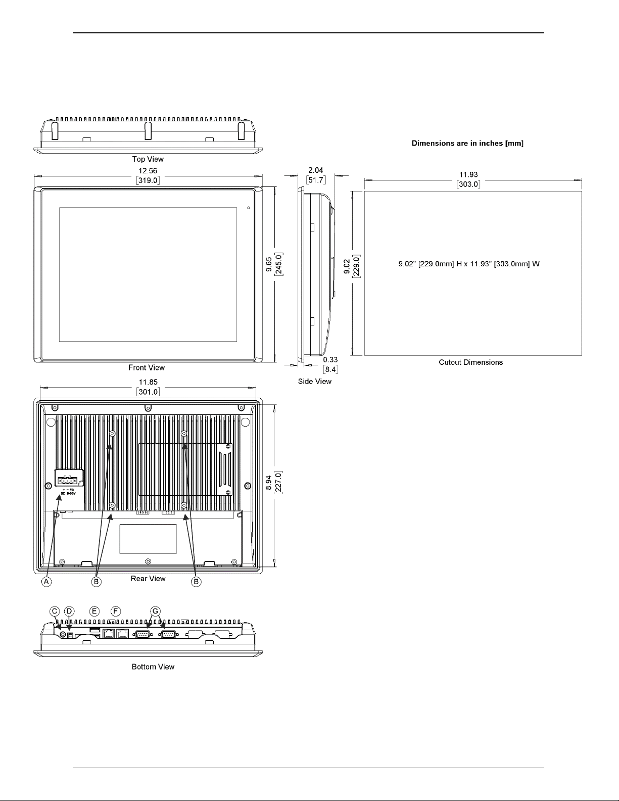
12.56 x 9.65 x 2.03”
[319 x 245 x 51.7 mm]
Net Weight
~ 2.52 lbs [1.14 kg]
~ 4.19 lbs [1.9 kg]
~ 4.19 lbs [1.9 kg]
~ 6.2 lbs [2.8 kg]
Panel Cutout
Dimensions (W x H)
7.56 x 5.43”
[192 x 138 mm]
8.74 x 6.57”
[222 x 167 mm]
10.71 x 6.93”
[272 x 176 mm]
11.93 x 9.02”
[303 x 229 mm]
Mounting
Panel mounting,
VESA 75 x 75 mm
Panel mounting,
VESA 75 x 75 mm
Panel mounting,
VESA 100 x 100 mm
Panel mounting,
VESA 100 x 100 mm
Mechanical
Construction
Silver aluminum front bezel and chassis
Operating
Temperature
32~122°F [0~50°C]
Storage
Temperature
-22~158°F [-30~70°C]
Relative Humidity
10 to 90% @ 40°C, non-condensing
Rating
IP66 / NEMA 4 when panel mounted
Environmental
Certification
CE / FCC Class A / RoHS
Operating
System
Microsoft Windows
Options
Microsoft Windows©10 IoT Enterprise Embedded 2019 LTSC 64-bit (EPKEA)
Microsoft WIndows©10 IoT Enterprise 2019 LTSC 64-bit (PKEA)
Notes
* CPU PassMark Benchmark comparison with OMI6800BA Series (Intel®Celeron™N2930 CPU)
** Additional SSD options available; contact Maple Systems for details.
Specifications subject to change without notice.

Operations Manual: OMI6800B Series 6
Operations Manual: OMI6800B Series 6
CPU
Intel®Pentium™Apollo Lake™N4200 Quad-Core 1.1GHz Processor
System Chipset
SoC
System
System Memory
Onboard DDR3L 4 GB 1600 MHz
USB
2 x USB 3.0 type A
Serial
1 x RS-232/422/485 DE9P, COM1 (default RS-232)
1 x RS-232 DE9P, COM2
Audio
1 x 3.5 mm line out
LAN
2 x GbE RJ-45
Power
3-pin connector header, DC power input
I/O Ports
Remote Power
Switch
2-pin connector header
Expansion
Expansion Slot
Optional Wi-Fi kit (Wi-Fi card and antenna)
Type
5-wire resistive touch
Interface
USB
Touch Screen
Light
Transmission
80+%
Display Type
15.0” XGA TFT LCD
15.6” WXGA TFT LCD
18.5” WXGA TFT LCD
21.5” FHD TFT LCD
Max. Resolution
1024 x 768
1366 x 768
1366 x 768
1920 x 1080
Max. Color
16.2M
16.7M
16.7M
16.7M
Luminance (cd/m²)
300
300
300
250
View Angle (H°/V°)
176/176
160/160
170/160
178/178
Contrast Ratio
2000:1
500:1
1000:1
3000:1
Display
Backlight Lifetime
(hours)
70,000+
50,000+
50,000+
30,000+
Solid State Drive
Type
1 x 2.5” SATA III, MLC
Solid State Drive
Capacity Options*
32, 64, 128, 256 GB SSD
Storage
SD Card Slot
1 x internal micro Secure Digital memory card socket, up to 32 GB
Input Voltage
9-36 VDC
9-36 VDC
9-36 VDC
9-36 VDC
Input Current
0.86-3.44 A
0.92-3.67 A
1.19-4.78 A
1.19-4.78 A
Electrical
Input Power (max).
31 W
33 W
43 W
43 W
Dimensions
(W x H x D)
16.14 x 12.20 x 2.15”
[410 x 310 x 54.67 mm]
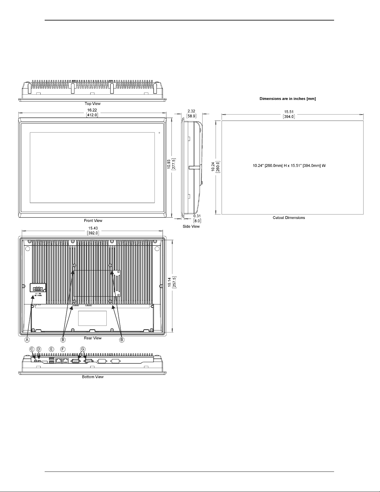
16.23 x 10.93 x 2.37”
[412 x 277.5 x 60.4 mm]
19.67 x 12.39 x 2.57”
[499.6 x 314.6 x 65.4 mm]
21.94 x 14.26 x 2.56”
[557.3 x 362.3 x 64.8 mm]
Net Weight
~ 9.7 lbs [4.4 kg]
~ 10.58 lbs [4.8 kg]
~ 13.01 lbs [5.9 kg]
~ 16.53 lbs [7.5 kg]
Panel Cutout
Dimensions (W x H)
15.43 x 11.50”
[392 x 292 mm]
15.51 x 10.24”
[394 x 260 mm]
18.98 x 11.69”
[482 x 297 mm]
21.22 x 13.54”
[539 x 344 mm]
Mounting
Panel mounting,
VESA 100 x 100 mm
Panel mounting,
VESA 100 x 100 mm
Panel mounting,
VESA 100 x 100 mm
Panel mounting,
VESA 100 x 100 mm
Mechanical
Construction
Silver aluminum front bezel and chassis
Operating
Temperature
32~122°F [0~50°C]
Storage
Temperature
-22~158°F [-30~70°C]
Relative Humidity
10 to 90% @ 40°C, non-condensing
Rating
IP66 / NEMA 4 when panel mounted
Environmental
Certification
CE / FCC Class A / RoHS
Operating
System
Microsoft Windows
Options
Microsoft Windows©10 IoT Enterprise Embedded 2019 LTSC 64-bit (EPKEA)
Microsoft WIndows©10 IoT Enterprise 2019 LTSC 64-bit (PKEA)
Notes
* CPU PassMark Benchmark comparison with OMI6800BA Series (Intel®Celeron™N2930 CPU)
** Additional SSD options available; contact Maple Systems for details.
Specifications subject to change without notice.

Operations Manual: OMI6800B Series 7
Operations Manual: OMI6800B Series 7
OMI6807 DIMENSIONS
A
Power Connector
B
VESA 75 mm Screw Holes
C
Line Out
D
Remote Power Switch Connector
E
USB 3.0 Host Ports
F
Gigabit Ethernet Ports
G
DE9P COM Ports

Operations Manual: OMI6800B Series 8
Operations Manual: OMI6800B Series 8
OMI6808 DIMENSIONS
A
Power Connector
B
VESA 75 mm Screw Holes
C
Line Out
D
Remote Power Switch Connector
E
USB 3.0 Host Ports
F
Gigabit Ethernet Ports
G
DE9P COM Ports

Operations Manual: OMI6800B Series 9
Operations Manual: OMI6800B Series 9
OMI6810 DIMENSIONS
A
Power Connector
B
VESA 100 mm Screw Holes
C
Line Out
D
Remote Power Switch Connector
E
USB 3.0 Host Ports
F
Gigabit Ethernet Ports
G
DE9P COM Ports
Operations Manual: OMI6800B Series 10
Operations Manual: OMI6800B Series 10
OMI6812 DIMENSIONS
A
Power Connector
B
VESA 100 mm Screw Holes
C
Line Out
D
Remote Power Switch Connector
E
USB 3.0 Host Ports
F
Gigabit Ethernet Ports
G
DE9P COM Ports

Operations Manual: OMI6800B Series 11
Operations Manual: OMI6800B Series 11
OMI6815 DIMENSIONS
A
Power Connector
B
VESA 100 mm Screw Holes
C
Line Out
D
Remote Power Switch Connector
E
USB 3.0 Host Ports
F
Gigabit Ethernet Ports
G
DE9P COM Ports
Operations Manual: OMI6800B Series 12
Operations Manual: OMI6800B Series 12
OMI6816 DIMENSIONS
A
Power Connector
B
VESA 100 mm Screw Holes
C
Line Out
D
Remote Power Switch Connector
E
USB 3.0 Host Ports
F
Gigabit Ethernet Ports
G
DE9P COM Ports

Operations Manual: OMI6800B Series 13
Operations Manual: OMI6800B Series 13
OMI6818 DIMENSIONS
A
Power Connector
B
VESA 100 mm Screw Holes
C
Line Out
D
Remote Power Switch Connector
E
USB 3.0 Host Ports
F
Gigabit Ethernet Ports
G
DE9P COM Ports

Operations Manual: OMI6800B Series 14
Operations Manual: OMI6800B Series 14
OMI6821 DIMENSIONS
A
Power Connector
B
VESA 100 mm Screw Holes
C
Line Out
D
Remote Power Switch Connector
E
USB 3.0 Host Ports
F
Gigabit Ethernet Ports
G
DE9P COM Ports

Operations Manual: OMI6800B Series 15
Operations Manual: OMI6800B Series 15
OVERVIEW OF OMI6800B SERIES
The OMI6800B Series is available in 7”, 8”, 10.1”, 12.1”, 15.1”, 15.6”, 18.5”, and 21.5” screen sizes. The
OMI6800B is fanless and compact with flat panel resistive touch screens, and is powered by the Intel®
Pentium™N4200 1.1 GHz quad-core processor with built-in 4GB DDR3L 1600MHz.
Front View of OMI6800B Series
Rear View
(OMI6812B shown)

Operations Manual: OMI6800B Series 16
Operations Manual: OMI6800B Series 16
I/O PORTS
COM1 and COM2:
Connector Type: DE9P male serial ports.
COM1*
COM2
Pin #
(RS-232 Default)
(RS422)
(RS485)
(RS232)
1
DCD
422_TX-
485-
DCD
2
RXD
422_TX+
485+
RXD
3
TXD
422_RX+
NC
TXD
4
DTR
422_RX-
NC
DTR
5
GND
GND
GND
GND
6
DSR
NC
NC
DSR
7
RTS
NC
NC
RTS
8
CTS
NC
NC
CTS
9
RI
NC
NC
RI
* Refer to “Setting COM1 Function” section to set the communication mode.
LINE OUT:
Connector Type: 3.5mm audio jack.
Line out HD Audio port can be connected to a speaker or headphones.
USB:
OMI6800B models have 2 ea. USB 3.0 type A ports.
Note: USB 3.0 allows data transfers up to 5000 Mb/s,
full-speed, and low-speed signaling. The total USB current limit is 2.0A.
LAN1 AND LAN2:
Standard 10/100/1000M (Gigabit) RJ-45 Ethernet ports
LINK LED (green) and ACTIVE LED (green or orange)
located at the left-hand and right-hand side of the Ethernet port indicate the activity and
transmission state of the network.
REMOTE POWER SWITCH CONNECTOR:
Two-Position Connector Header, 2.5mm pitch.
OMI6800B Series units include the matching connector plug.

Operations Manual: OMI6800B Series 17
Operations Manual: OMI6800B Series 17
REMOTE POWER SWITCH CONFIGURATION OPTION
By default, your OMI6800B Series unit is configured to boot up automatically upon application of power,
with no configuration changes necessary. In the event that DC power is lost, the unit will automatically
boot up again once DC power is restored.
If you wish to control the unit’s on/off status via a Remote Power Switch, simply connect a normally open
momentary-type switch wired to the included 2-pin connector. The connector plug accepts min. 28AWG
and max. 20AWG solid or stranded wire connection, with push-type insertion.
When the unit is powered, pressing the switch will perform a proper Windows shut down. If the DC power
supply to the OMI6800B Series is still providing power, simply press your power switch again to boot your
OMI6800B Series unit. When the unit is properly shut down, then it is safe to remove DC power. When DC
power is provided to the OMI6800B Series once again, the unit will automatically boot.
Warning: Maple Systems does not recommend shutting down the
OMI6800B Series by cutting DC power to the unit.
Always perform a Windows Shut Down procedure when you wish to turn the unit off.
Cutting DC power to the OMI6800B Series can corrupt the Windows Operating System,
or other software or hardware components of your OMI. Damage caused by improper
application or removal of power may not be covered under the OMI6800B Series
Warranty.

Operations Manual: OMI6800B Series 18
Operations Manual: OMI6800B Series 18
VESA MOUNTING
The OMI6800B Series offer VESA mounting as an option. VESA 75 x 75mm or VESA 100 x 100mm
threaded inserts, depending on your display size, are located on the rear of the unit. Use the M4 threaded
mounting screws included with the VESA mounting hardware to mount the OMI6800B as illustrated in the
figure below.
Use VESA mounting hardware suitable for your intended application; Maple Systems is not responsible
for damage to unit, mounting surface, or to other components, caused by improper mounting.
PANEL MOUNTING
In addition to VESA mounting, your OMI6800B Series can be mounted in a panel using the mounting
holes located on the sides and top of the unit. Use the included clamps to fasten your OMI6800B Series
unit to a panel, cut out to the proper dimensions on the datasheet corresponding to your display size.
Tighten the nuts no more than 5.1 inch/lbs. to ensure an adequate seal. Excessive torque may negate
NEMA or IP rating, or cause damage to the unit or panel.
Maple Systems is not responsible for damage to unit, mounting surface, or to other components, caused
by improper mounting.
Note: The image above is a representative image of the panel mounting process; your specific OMI6800B
Series unit may differ in appearance, but mounting is functionally similar.

Operations Manual: OMI6800B Series 19
Operations Manual: OMI6800B Series 19
DRIVER INSTALLATION
Your OMI6800B series comes with all necessary drivers pre-installed. As such, driver installation is not
normally needed. However, there may be times when a driver requires re-installation. Use the Support
DVD that came with your unit to install all non-Windows Operating System Drivers. If you no longer have
your Support DVD, visit the Support Center of the Maple Systems website for driver download.
Equipment required:
OMI6000 Support DVD
USB External DVD drive
Instructions:
Plug in the USB external DVD drive into one of the USB ports.
Load the support DVD into the external drive.
Access the OMI6000 support DVD and open the OMI6800B folder.
Open the folder corresponding to the driver you want to install / reinstall.
Double-click the application (setup.exe) file to begin driver installation.
Follow the instructional prompts on the screen.
We recommend that you restart your computer when prompted, and after completion of all driver
installations.
WINDOWS OPERATING SYSTEM REINSTALLATION
In the unlikely event of a system failure requiring reinstallation of the Windows Operating System, use the
OS Recovery DVD (enclosed with Non-Embedded Operating Systems only) to reinstall Windows as it
arrived to you from Maple Systems. You will need to re-activate Windows using the Product Key located
on the rear panel of your unit, adjacent to the product label.
In the event that you wish to update your Windows Operating System (Non-Embedded Operating
Systems only), simply connect the OMI6800B Series unit to the Internet and run the Windows Update
utility.
Embedded Operating Systems do not come with an OS Recovery DVD. In the extremely unlikely event
the Windows OS needs to be reinstalled, contact your Maple Systems Sales Engineer for instructions.

Operations Manual: OMI6800B Series 20
Operations Manual: OMI6800B Series 20
BIOS CONFIGURATION OPTIONS
INTRODUCTION
The BIOS (Basic Input/Output System) installed in the ROM of your OMI6800B Series supports Intel®
processors. The BIOS provides critical low-level support for standard devices such as disk drives and
serial ports. The BIOS also provides a Setup utility program that allows the user to specify system
configuration and setting options.
Warning: Changing settings or configurations within the BIOS of your OMI6800B
can adversely impact the operation of your unit if incorrectly performed.
Maple Systems provides the below instructions solely for the operations specified, and
is not responsible for improper unit operation caused by changing settings or entries
other than those explicitly listed below.
ENTERING SETUP
When the system is powered on, the BIOS will enter the Power-On Self Test (POST) routines
and the following message will appear on the screen:
Example of initial POST screen. Your POST screen may appear different.
Press the <Delete> key immediately during the POST portion of your PC’s bootup sequence to enter the
BIOS. The Main Menu containing the system summary information will appear.
This manual suits for next models
8
Table of contents
Other Maple Systems Industrial PC manuals


