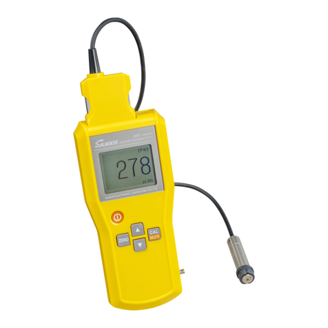
SANKO SM-1100 User manual

ELECTROMAGNETIC TYPE
DIGITAL COATING THICKNESS METER
SM‑1100
INSTRUCTION MANUAL
CAUTIONS:
●Before using the Meter, read this INSTRUCTION MANUAL thoroughly
and use the Meter correctly.
●Keep this INSTRUCTION MANUAL carefully and refer to this, when
necessary.
●In the event of any doubt arising, the original INSTRUCTION MANUAL
in Japanese is to be final authority.
※Sensitivity of the probe of this Meter has been adjusted so as to
deal with the measurement of a thicker film thickness.
When the probe is left on a metal e.g. steel desk etc. the Meter may
indicate a certain value or「HHH」occasionally.
SANKO ELECTRONIC LABORATORY CO., LTD.
(株式会社 サンコウ電子研究所)

‑1‑
CONTENTS
ITEM PAGE
1.PRINCIPLE 2
2.APPLICATIONS 2
3.SPECIFICATIONS 3
4.PARTS IDENTIFICATION 4
5.PREPARATION 5
5‑1.Preparation of the zero plate 5
5‑2.Connecting (Disconnecting) the probe 5
6.OPERATING INSTRUCTIONS 6
6‑1.Power ON 6
6‑2.Power OFF 6
6‑3.Zero adjustment 7
6‑4.Standard calibration(CAL) 8
6‑5.Resetting the working curve 10
6‑6.Measurement 11
7.ADDITIONAL FUNCTIONS 12
7‑1.Converting the key lock mode 12
7‑2.Setting the upper and lower limit values 13
7‑3.Releasing the upper and lower limit values 14
7‑4.Statistical function 15
7‑4‑1.Starting of the statistical function and alteration of 15
the indicating data
7‑4‑2.Statistical measurement mode 15
7‑4‑3.Indication of the measured numbers 16
7‑4‑4.Indication of the mean value 16
7‑4‑5.Indication of the maximum value 16
7‑4‑6.Indication of the minimum value 17
7‑4‑7. Indication of the standard deviation value 17
8.INDICATING /RELEASING THE MEMORIZED DATA ON THE LCD 18
8‑1.Indicating the data on the LCD 18
8‑2.Releasing the indication of the data to the LCD 19
8‑3.Erasing the data while indicating on the LCD 19
9.ERASING THE MEMORIZED DATA 20
9‑1.Erasing all the data 20
9‑2.Erasing the last data 21
10.REPLACING THE BATTERY 22
11.MAINTENANCE AND INSPECTION 22
12.CARES TO RAISE AN ACCURACY OF THE MEASUREMENT 23

‑2‑
Before using the Meter, read this INSTRUCTION MANUAL thoroughly and use
the Meter correctly.
Keep this INSTRUCTION MANUAL carefully and refer to this, when necessary.
1.PRINCIPLE
When an iron is moved toward or away from
a steel core coil, self-inductance of the coil changes
in accordance with a slight changes of its distance.
This principle is utilized to measure the thickness (D)
of non-magnetic surface treated coating on iron substrate.
2.APPLICATIONS
The Meter is used for non-destructive measurement of the thickness of a non-conductive film such as coating,
lining, etc. applied to iron substrate including steel and ferritic stainless steel (SUS 430 etc).
The Meter can be applicable for various domestic and foreign standards and rules.
●Paints Machines, Appliances, Automobiles, Steel furniture, Bridges,
Ships, Cast iron tubes, Steel structures, etc.
●Linings Resin, Tar epoxy, Rubber, Enamel, etc.
●Platings Nonmagnetic platings such as Chrome, Zinc, Copper, Tin, Electroless nickel
excluding Electrolysis nickel plating
●Metallikon, Phosphoric acid film, Oxidation acid film, Spray deposit, etc.
●Resin film, Nonmagnetic metal foil
( Thickness is measured on the basis of a steel plate placed underneath of the film or foil.)

‑3‑
3.SPECIFICATIONS
・Name and type Electromagnetic type digital coating thickness meter SM-1100
・Measuring method Electromagnetic induction type
・Measuringrange 0to8.00mm
◎1.00 to 8.00 (mm unit)
◎0to999(μm unit)
・Accuracy ±0.01mm on uniform surface or ±3 %of reading
・Indication Digital display on large size Liquid Crystal Display (LCD)
With hold function
・Resolution 0.01 mm (1.00 to 8.00 mm)
1μm(0to999μm)
・Probe One point contact constant pressure type with V-groove
φ18 × 55 mm
・Additional functions 1) Conversion of the key lock mode
2) Setting of the upper/lower limit values
3) Memory of 1800 measurement values
4) Statistical calculating functions such as measurement numbers,
mean value, maximum value, minimum value, standard deviation value
5) Auto power off (after about 5 minutes)
・Power source Dry batteries R03 (1.5V) × 4 pcs.
With auto power off function
・Operatingtemp. 0to40℃(except dew condensing condition)
・Dimensions 80(W) × 35(H) × 150(D) mm
・Weight approx. 330g (including batteries)
・Accessories Standard thickness plate, Zero plate for checking the Meter, Dry battery,
Carrying bag
※Specifications and appearance are subject to modify for improvement without prior notice.

‑4‑
4.PARTS IDENTIFICATION
⑨⑩
⑪
①⑤
②⑥
③⑦
④⑧
⑫
①POWER key Key for power ON/OFF
②ZERO key Key for zero adjustment
③LOCK key Key for locking all keys except ON/OFF key
④∧
・
∨key Key for standard calibration with the standard thickness plate and
setting the upper/lower limit values
⑤H/L key Key for setting the upper/lower limit values
⑥STAT key Key for converting the normal measurement mode and statistical
measurement mode
Also, for converting the indicating kinds of statistical data
in the statistical measurement mode
⑦DATA OUT key Key for outputting the stored data to the connected printer
in the statistical measurement mode
⑧DATA CLR key Key for erasing all or part of the stored data in the
statistical measurement mode
⑨Printer connector Connector for connecting the printer
⑩Probe connector Connector for connecting the probe
⑪LCD display Indicating part of the measured values
⑫Hand strap
Be sure to pass the hand strap around the wrist to prevent the Meter
from dropping.

‑5‑
5.PREPARATION
5‑1. Preparation of the zero plate
Prepare the substrate which is the same kind, thickness and shape with an
object to be measured.
The attached zero plate for checking the Meter, SUS 430 Ferrite stainless
steel, is used for the operation check of the Meter.
Prepare the substrate of an actual object to be measured.
・Same kind The same kind of material as the substrate of an object to be measured
・Same thickness Nearly the same thickness as the substrate of an object to be measured
・Same shape The same shape in pipe diameter, curvature, geometrical shape, etc. as the
substrate of an object to be measured
・Size Substrate with an enough area on which the probe can be easily operated
・Surface condition Untreated (unoxidized etc.) substrate having smooth surface Remove rust,
dirt or dust, if any.
5‑2.Connecting(Disconnecting) the probe
Carry out the connection (disconnection) of the probe by the following procedures.
・Be sure to keep the Power OFF.
・The probe cannot be substituted with other probe.
UsetheprobewhichisthesamenumberwiththeMeternumber.
◎ Connecting method
Insert the probe into the probe
connector keeping the wide cut right
ward and tighten it by turning
Aclockwise.
◎ Disconnecting method
Release by turning A counter-clockwise
and calmly pull the probe out of
the connector.
Don't pull the cord as it
causes breaking of cord.
※When the probe is not connected to the Meter or any system is out of order even if the probe
is connected, the indication changes as follows after turning ON the power key.
If the probe is disconnected in power ON condition, 「PE」is indicated on the display and power
is automatically cut off. (「PE」is abbreviation of Probe Error. )
↓
→
The buzzer emits a beeping sound. Power is automatically cut off.
−−− μm
Fe
PE
Fe Fe

‑6‑
6.OPERATING INSTRUCTIONS
6‑1. Power ON
Press the「ON/OFF」key ①after connecting the probe.
[Indication on the LCD ⑪changes as follows.]
↓
Inside of the Meter is being initialized.
↓Keep the probe turn towards the air during this period.
↓←The buzzer emits a beeping sound.
The Meter is ready for measurement.
・When power ON, the last measured value of
the previous measurement is indicated.
・When the first power ON or all data are erased in the
statistical mode, [ −] is indicated.
6‑2. Power OFF
Press the「ON/OFF」key ①.
[Indication on the LCD ⑪changes as follows]
↓←The buzzer emits a beeping sound.
Power is automatically cut off.
−−− μm
Fe
−− μm
Fe
3.56 mm
Fe
−μm
Fe
μm
Fe

‑7‑
6‑3.Zero adjustment
Carry out the adjustment in surely normal measurement mode.
(Unit [μm] and [mm] are indicated non blinking.)
Press the probe against the substrate for adjustment (zero plate).
[Indication on the LCD ⑪changes as follows.]
↓←The buzzer emits a beeping sound.
Zero plate
Measured value [XX] is
indicated on the LCD ⑪.
↓
Press the「ZERO」key ②.
(Both the probe contact to zero plate or not is possible.)
↓←The buzzer emits a beeping sound.
[CAL] is indicated on the upper left of the LCD ⑪.
[ 0 ] is indicated.
↓←The buzzer emits a beeping sound.
Press the probe against the zero plate several times, when closed values to [ 0 ] are indicated on the LCD ⑪,
the adjustment is acceptable.
When the indications are away from [ 0 ], repeat above procedures several times.
※When 「LLL」 is indicated while zero adjusting, its adjusting point is widely deviated
from a right position.
Repeat the zero adjustment 2 to 4 times after confirming no coating is applied to the
substrate and confirm zero is stably indicated.
【NOTICE】
Normal measurement mode : Units [μm] and [mm] are indicated non blinking on the right hand of the LCD ⑪.
Statistical measurement mode : Units [μm] and [mm] are indicated blinking on the right hand of the LCD ⑪.
Carry out the adjustment in surely normal measurement mode.
When the zero adjustment is carried out in the statistical measurement mode, [ 0 ] data while adjusting
is stored in the memory.
Stored 1 data is automatically erased by pressing [ZERO] key ②.
XX μm
Fe
CAL 0
Fe
0μm
Fe

‑8‑
6‑4. Standard calibration (CAL)
Carry out the calibration in surely normal measurement mode.
(Unit[μm]and [mm] are indicated non blinking.)
Place the standard thickness plate on the zero plate,
and press the probe against it.
Select a little thicker standard thickness plate than
a film thickness to be measured. Standard
[Indications on the LCD ⑪change as follows.] thickness plate
Zero plate
↓←The buzzer emits a beeping sound.
(Example : Standard thickness plate of 3.00 mm th.)
↓
Match the indicated value on the LCD ⑪to the thickness of the standard thickness plate
by pressing the「∧」・「∨」key ④.
(This operation is possible for both the probe is contacting to the standard thickness plate or not.)
↓←When the「∧」・「∨」key ④is pressed, [CAL]
is indicated on the upper left of the LCD ⑪with a
beeping sound of the buzzer and indication
[YYY] of left figure changes.
The Indicated values traverse quickly by keeping on
the「∧」・「∨」key ④pressing.
↓
←When the indication match to the thickness of the
standard thickness plate, stop the operation of
the「∧」・「∨」key ④.
↓
The Meter is ready for measurement.
Press the probe against the standard thickness plate placed on the zero plate several times.
When the indication on the LCD ⑪is the same thickness or near with the standard thickness plate,
the calibration is acceptable.
When the indication deviates from the thickness of the standard thickness plate, repeat above
procedures several times.
2.97 mm
Fe
CAL YYY mm
Fe
3.00 mm
Fe

‑9‑
【NOTICE 】
●Waitfor10to15minutes ※after power ON for the adjustment or calibration to raise the accuracy.
※Power is cut off in about 5 minutes by the working of the auto power OFF function.
In this case, turn ON the power key ①again and fully warm up the Meter.
●Carry out the「zero adjustment」and the「standard calibration」to confirm the accuracy,
even if on the way of the measurement.
●Applicable range of the standard calibration(CAL) is 10 μmto8.00mm.
When it is out of the applicable range, [ LLL ] or [ HHH ] is indicated.
When the indication is in locked condition, operate the Meter according to the next item
「6-5. Resetting the working curve 」.
●When the new values are set for both zero adjustment and standard calibration , the last characteristic
of substrate (working curve) is erased and new set value (working curve) is memorized.
●If the calibration is carried out with the standard thickness plate in the statistical measurement mode,
the data of the standard thickness plate while calibrating are stored in the memory.
The stored 1 data is automatically erased by pressing the「∧」or「∨」key ④.
But, when the「∧」or「∨」key ④is not pressed, the measured data is stored in the memory.
Carry out the calibration in surely normal measurement mode.
●Payattentiontoavoidmis-operationbyusingthelockkeyasshowninitem
「7-2. Converting the key lock mode」after completing the adjustment or calibration.

‑10‑
6‑5.Resetting the working curve
When the batteries were replaced, indication was locked or measurement, zero adjustment,
standard calibration (CAL) became impossible for operation, reset the Meter by following method.
The Meter is in power ON condition.
↓←Press the「∨」key ④continuously 5 times while
keepingonthe「ZERO」key ②pressing.
[CAL]is indicated on the upper left of the LCD ⑪,
and[ 0 ] is indicated blinking. The buzzer emits a beeping
sound for every press of the「∨」key ④.
↓←The buzzer emits beeping sounds.
[-E-] is indicated for 3 seconds.
↓
←The Meter is restored to the possible condition for the
measurement.
Carry out the zero adjustment and standard
calibration again, if necessary.
【NOTICE】
The operation for resetting can not be carried out under the following condition.
Be sure to complete the operation for indicating the statistical values.
・While indicating the statistical values
・While setting the upper and lower limit values
3.00 mm
Fe
CAL 0
Fe
CAL ―E―
Fe
―μm
Fe

‑11‑
6‑6.Measurement
Be sure to pass the hand strap ⑫ around the wrist to prevent the Meter
from dropping.
When the above mentioned zero adjustment and standard calibration are completed, the Meter
is ready for the measurement.
2 kinds of the measurement method are applicable.
・Normal measurement mode Indication only, no memory
・Statistical measurement mode Indication and memory together
(Refer to item No.7-4-1 and No.7-4-2)
Hold the mid-part of the probe as shown in left figure and press it against
the surface of an object to be measured vertically, quickly and calmly.
The Meter emits a beeping sound and the measured value is indicated on
the LCD ⑪.
If no sound is emitted, press again after removing the probe about 20 to 30 cm
from the surface.
※Make use of the key lock mode function to prevent the mis-operation
while measuring.
◆When the measurement is not carried out for more than about 5 minutes after power ON,
the power will be cut off by the working of the auto power OFF function.
The last measuring condition is restored by the working of the resuming function at the succeeding
power ON.
Correct usage Incorrect usage
Hold the mid-part of the probe and Don't tilt the probe Don't slide the probe Don't press the probe
press it down vertically and calmly against an object to be side ways while pressing. against an object to be
against the surface of an object to measured. The accurate Both the probe and an measured too slowly.
be measured. The measured value is measured value can not object to be measured Measurement error will
indicated with a beeping sound. be obtained. will be damaged. cause to be enlarged.
If no sound is emitted, measure again
after removing the probe about 20 to
30cm from the surface.
※When the probe is left on a magnetic metal such as a steel desk etc. after measurement a certain value or
[HHH] will be indicated occasionally.
It comes from the characteristics that the probe try to read the film thickness applied to a magnetic metal.
Not to make the Meter indicate above value, leave the probe keeping above 50mm or more away from a magnetic
metal. (Example: Leave the probe on a magnetic subject such as a wood 50mm or more in thickness.)
Moreover, even if a certain value or [HHH] is indicated, the Meter can be used normally by proceeding
the measurement again.

‑12‑
7.ADDITIONAL FUNCTIONS
7‑1. Converting the key lock mode
Press the「LOCK」key ③in power ON condition.
↓
Then the buzzer emits 3 beeping sounds.
All keys except the「power」key ①can not be operated to prevent from mis-operation.
↓
To release the key lock mode, power OFF once and power ON again.

‑13‑
7‑2.Setting the upper and lower limit values
Press the「H/L」key ⑤in power ON condition
↓←The buzzer emits a beeping sound.
[ H ] is indicated blinking for about 3 seconds.
↓←Indication changes after about 3 seconds.
1) When the upper limit value has not been previously set ;
[−−−] is indicated blinking in place of [XXX].
2) When the upper limit value has been set ;
Previously set value is indicated blinking in place of [XXX].
↓
In case the upper limit value is set.
↓←Match the indication of the
LCD ⑪to the upper limit In case the upper limit
value by pressing the「∧」 value is not set in case 1).
・「∨」key ④. In case the upper limit value
(Ex.Upper limit value is 1.80mm) is not changed in case 2).
←[1.80mm] is indicated blinking.
↓
Press the「H/L」key ⑤.
↓←The buzzer emits a beeping sound.
「L」is indicated blinking for about 3 seconds.
↓←Indication changes after about 3 seconds.
3) When the lower limit value has not been previously set ;
[−−−] is indicated blinking in place of [ YYY ].
4) When the lower limit value has been set ;
Previously set value is indicated blinking in place of [ YYY ].
↓
In case the lower limit value is set.
↓←Match the indication of the
LCD ⑪to the lower limit In case the lower limit
value by pressing the「∧」 valueisnotsetincase3).
・「∨」key ④. In case the lower limit
(Ex.Lower limit value is 1.50mm) value is not changed in
case 4).
←[1.50mm] is indicated blinking.
↓
Press the「H/L」key ⑤.
↓
The Meter is restored to the possible condition for the measurement with a beeping sound.
H
Fe
XXX μm
Fe
1.80 mm
Fe
L
Fe
YYY μm
Fe
1.50 mm
Fe

‑14‑
7‑3.Releasing the upper and lower limit values
Press the「H/L」key ⑤in power ON condition.
↓
The mode proceeds to the previous item mode「7-2 Setting the upper and lower limit values 」.
↓
Press the「DATA CLR」key ⑧.
↓←The buzzer emits a beeping sound.
[ EHL ] is indicated blinking.
↓
When erase the upper and lower limit values,
press the「DATA CLR」key ⑧again.
↓←The buzzer emits a beeping sound.
Blinking of [ EHL ] stops and
the upper and lower limit values
are erased.
In case of cancelling
↓the erasing.
The Meter is restored to the
possible condition for the
measurement.
Press the「H/L」key ⑤
↓
←The buzzer emits a beeping sound.
Erasing the upper and lower limit values are cancelled.
(No set upper and lower limit values are erased.)
The Meter is restored to the possible condition for the
measurement.
【NOTICE】
In case of setting the upper and lower limit values, set the maximum setting value of
the lower limit value so as to surely satisfy with the following conditions:
・Lower limit value in the range of 1 mm or less : [Upper limit value -1μm]
(Keep the difference between upper limit value and lower limit value 1μm or more)
・Lower limit value in the range of 1mm or more : [Upper limit value-0.01mm]
(Keep the difference between upper limit value and lower limit value 0.01mm or more)
EHL
Fe
EHL
Fe
―μm
Fe
―μm
Fe

‑15‑
7‑4.Statistical function
7‑4‑1.Starting of the statistical function and alteration of the indicating data
【Normal measurement mode】
↓←Press the 「STAT」key ⑥. (1st time)
【Statistical measurement mode】
↓←Press the 「STAT」key ⑥.※(2nd time)
【Indication of measured numbers 5E】
↓←Press the 「STAT」key ⑥. (3rd time)
【Indication of mean value E】
↓←Press the 「STAT」key ⑥.(4thtime)
【Indication of Max. value H】
↓←Press the 「STAT」key ⑥.(5thtime)
【Indication of Min. value L】
↓←Press the 「STAT」key ⑥.(6thtime)
【Indication of standard deviation value P】
↓←Press the 「STAT」key ⑥.
※When no statistical data have been stored or the data have been erased, [5E] is indicated
blinking with a beeping sound, and the mode proceeds to the normal measurement mode.
7‑4‑2.Statistical measurement mode
Measured data up to maximum 1800 points can be stored in memory in the measurement order,
and Measured numbers, Mean value, Maximum value, Minimum value, Standard deviation value
can be indicated in order on the LCD ⑪.
Press the「STAT」key ⑥. (1st time from the normal measurement mode)
↓
←The buzzer emits a beeping sound.
[ 5E ] is indicated blinking for about 3 seconds.
↓←The Meter becomes the possible condition for the memory
measurement in the statistical measurement mode,
and every time of the measurement the data are stored
in the memory. Indication of the unit [μm] or [mm] is
blinking during the statistical measurement mode.
[ XXX ] is the last measured data stored in the memory.
When no data have been stored in the memory,
[−] is indicated.
5E
Fe
XXX mm
Fe

‑16‑
7‑4‑3.Indication of the measured numbers
Press the「STAT」key ⑥. (2nd time from the normal measurement mode)
↓←The buzzer emits a beeping sound.
[ 5E ] and the measured numbers [XXX] are indicated alternately.
Indicating time of [ 5E ] : about 0.5 seconds
Indicating time of [XXX] : about 2 seconds
↓
7‑4‑4.Indication of the mean value
Press the「STAT」key ⑥. ( 3rd time from the normal measurement mode )
↓←The buzzer emits a beeping sound.
[ E ] and the mean value [XXX] are indicated alternately.
Indicating time of [ E ] : about 0.5 seconds
Indicating time of [XXX] : about 2 seconds
↓
7‑4‑5.Indication of the maximum value
Press the「STAT」key ⑥. ( 4th time from the normal measurement mode )
↓←The buzzer emits a beeping sound.
[ H ] and the maximum value [XXX] are indicated
alternately.
Indicating time of [ H ] : about 0.5 seconds
Indicating time of [XXX] : about 2 seconds
↓
5E
Fe
XXX
Fe
E
Fe
XXX mm
Fe
H
Fe
XXX mm
Fe

‑17‑
7‑4‑6.Indication of the minimum value
Press the「STAT」key ⑥. ( 5th time from the normal measurement mode )
↓←The buzzer emits a beeping sound.
[ L ] and the minimum value [XXX] are indicated
alternately.
Indicating time of [ L ] : about 0.5 seconds
Indicating time of [XXX] : about 2 seconds
↓
7‑4‑7.Indication of the standard deviation value
Press the「STAT」key ⑥. (6th time from the normal measurement mode)
↓←The buzzer emits a beeping sound.
[ P ] and the standard deviation value [XXX]
are indicated alternately.
Indicating time of [ P ] : about 0.5 seconds
Indicating time of [XXX] : about 2 seconds
↓
L
Fe
XXX mm
Fe
P
Fe
XXX mm
Fe

‑18‑
8.INDICATING/RELEASING THE MEMORIZED DATA ON THE LCD
8‑1.Indicating the data on the LCD
As mentioned in the previous item 7-4-2, the measurement data stored in the
memory in the statistical measurement mode can be indicated on the LCD ⑪.
Press the 「DATA OUT」key ⑦in the ※In other mode, [EEO] is indicated
statistical measurement mode.※blinking and returns to the last mode.
↓←The buzzer emits a beeping sound.
[ LP ] is indicated blinking.
↓
Find out the memory No. of needed Notice:
data by pressing 「∧」・「∨」key ④When「∧」key ④is pressed, the indication
and stop the key operation at the of the data move up like No.1,2,3・・・.
indication No. When「∨」key ④is pressed, the indication
Memory No. traverse quickly by keeping of the data move down from the last memory No.
on「∧」・「∨」key ④pressing. When「∧」・「∨」key ④is pressed again
↓after suspending the key operation, No. starts
from the suspended memory No.
Memory No. [NNN] and data [XXX] are
indicated alternately on the LCD ⑪.
Indicating time of memory No. [NNN] :
About 0.5 seconds
↓↑ Indicatingtimeofdata[XXX]:
About 2 seconds
Moreover, when the upper and lower limit values
have been set, the indication will be as follows:
◎In case of a normal value:
Indicating time of memory No. [NNN] :
About 0.5 seconds
Indicating time of data [XXX] :
About 2 seconds
◎In case in excess of a normal value :
Indicating time of Memory No. [NNN] :
About 0.5 seconds
Indicating time of [HHH] or [LLL] :
About 0.5 seconds
Indicating time of data [XXX] :
About 2 seconds
XXX mm
Fe
NNN
LP
Fe

‑19‑
8‑2.Releasing the indication of the data on the LCD
For releasing the indication of the memorized data on the LCD ⑪,pressthe「DATA OUT」key ⑦.
By this operation, the mode returns to the last statistical measurement mode just before this operation.
Press the 「DATA OUT」key ⑦.
↓←The buzzer emits a beeping sound.
Blinking indication of the memory No. [NNN]
and data [XXX] close and the mode returns to
the last statistical measurement mode.
Unit [mm] or [μm] is indicating blinking.
8‑3.Erasing the data while indicating on the LCD
Data can be erased even while indicating the memorized data on the LCD ⑪.
(Refer to the later item 10-2 Erasing the last data, together.)
Memory No. [NNN] and data [XXX] are indicated
alternately on the LCD ⑪.
When the upper and lower limit values have been set
and exceed them, [HHH] or [LLL] is indicated also.
↑↓
↓
Press the「DATA CLR」key⑧.
↓←The buzzer emits beeping sounds, and [‑E‑]is
indicated on the LCD ⑪for about 1 second.
Indicated memory No. and data including the
signal of the upper and lower limit are erased.
Next data are passed on for the erased part and
memory No. [NNN] and data [XXX] including
signal of the upper and lower limit are indicated
alternately on the LCD ⑪.
XXX mm
Fe
NNN
XXX mm
Fe
―E―
Fe
Table of contents
Other SANKO Measuring Instrument manuals
SANKO
SANKO SP-3300D User manual

SANKO
SANKO SWT-7000 III User manual

SANKO
SANKO AQ-30 User manual

SANKO
SANKO SWT-7000 III User manual

SANKO
SANKO SWT-7200 II User manual

SANKO
SANKO MR-300 User manual
SANKO
SANKO SWT-7200IV User manual

SANKO
SANKO PM-101 User manual

SANKO
SANKO MR-200 II User manual

SANKO
SANKO SAMAC-F User manual
Popular Measuring Instrument manuals by other brands

B&W Tek
B&W Tek NanoRam Series Quick start manual

VWR
VWR avantor CO-2500L instruction manual

Hanna Instruments
Hanna Instruments Checker HI718 instruction manual

PureAire Monitoring Systems
PureAire Monitoring Systems 99019 instruction manual

Michell Instruments
Michell Instruments XTP601 user manual

VOLTCRAFT
VOLTCRAFT AM-96X96 operating instructions