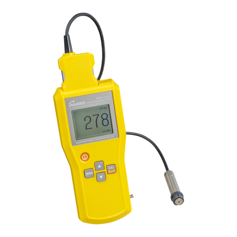
SANKO SWT-7200IV User manual

SANKO Coating Thickness Meter
SWT-7200Ⅳ
Instruction Manual
Caution
●Read the manual thoroughly and use the meter correctly.
●Keep the manual with care and refer to it when necessary.
SANKO ELECTRONIC LABORATORY CO., LTD.
Tokyo・Osaka・Sendai・Nagoya・Fukuoka・Kawasaki
August 2023

Contents Pages
Attention for safety ・・・・・・・・・・・・・・・・・・・・・・・・・・・・・・・・・・・・・・・・・・・・・・・・・・・・・・・・・・・・・・・・・・・・・・・・・・・
1
Notes ・・・・・・・・・・・・・・・・・・・・・・・・・・・・・・・・・・・・・・・・・・・・・・・・・・・・・・・・・・・・・・・・・・・・・・・・・・・・・・・・・・・・・・・
3
Get started ・・・・・・・・・・・・・・・・・・・・・・・・・・・・・・・・・・・・・・・・・・・・・・・・・・・・・・・・・・・・・・・・・・・・・・・・・・・・・・・・・・・
4
・Contents in a package ・・・・・・・・・・・・・・・・・・・・・・・・・・・・・・・・・・・・・・・・・・・・・・・・・・・・・・・・・・・・
4
・Names of part ・・・・・・・・・・・・・・・・・・・・・・・・・・・・・・・・・・・・・・・・・・・・・・・・・・・・・・・・・・・・・・・・・・・・
5
・Items displayed on LCD ・・・・・・・・・・・・・・・・・・・・・・・・・・・・・・・・・・・・・・・・・・・・・・・・・・・・・・・・・・・
7
・How to fit batteries ・・・・・・・・・・・・・・・・・・・・・・・・・・・・・・・・・・・・・・・・・・・・・・・・・・・・・・・・・・・・・・・
9
・How to connect, disconnect probes ・・・・・・・・・・・・・・・・・・・・・・・・・・・・・・・・・・・・・・・・・・・・・・・・
10
・How to hold probes ・・・・・・・・・・・・・・・・・・・・・・・・・・・・・・・・・・・・・・・・・・・・・・・・・・・・・・・・・・・・・・・
11
・How to press a probe to an object ・・・・・・・・・・・・・・・・・・・・・・・・・・・・・・・・・・・・・・・・・・・・・・・・・
11
How to operate ・・・・・・・・・・・・・・・・・・・・・・・・・・・・・・・・・・・・・・・・・・・・・・・・・・・・・・・・・・・・・・・・・・・・・・・・・・・・・・・
12
(1) How to switch power source ・・・・・・・・・・・・・・・・・・・・・・・・・・・・・・・・・・・・・・・・・・・・・・・・・・・・・・
12
(2) How to switch off ・・・・・・・・・・・・・・・・・・・・・・・・・・・・・・・・・・・・・・・・・・・・・・・・・・・・・・・・・・・・・・・・
12
(3) How to select 「Cal. No. 」(Calibration curve) ・・・・・・・・・・・・・・・・・・・・・・・・・・・・・・・・・・・・・・
13
(4)Zeroing ・・・・・・・・・・・・・・・・・・・・・・・・・・・・・・・・・・・・・・・・・・・・・・・・・・・・・・・・・・・・・・・・・・・・・・・・・・
14
(5) Calibration standard (CAL) ・・・・・・・・・・・・・・・・・・・・・・・・・・・・・・・・・・・・・・・・・・・・・・・・・・・・・・・・
16
(6) Zeroing -in special cases -・・・・・・・・・・・・・・・・・・・・・・・・・・・・・・・・・・・・・・・・・・・・・・・・・・・
18
(7) 2-point calibration in case it is difficult to perform 「Zeroing」・・・・・・・・・・・・・・・・・・・・・・・・・
21
(8) How to delete calibration ・・・・・・・・・・・・・・・・・・・・・・・・・・・・・・・・・・・・・・・・・・・・・・・・・・・・・・・・・
25
《Collective deletion》・・・・・・・・・・・・・・・・・・・・・・・・・・・・・・・・・・・・・・・・・・・・・・・・・・・・・・・・・・・・・
25
《Selective deletion》・・・・・・・・・・・・・・・・・・・・・・・・・・・・・・・・・・・・・・・・・・・・・・・・・・・・・・・・・・・・・・
26
Measuring ・・・・・・・・・・・・・・・・・・・・・・・・・・・・・・・・・・・・・・・・・・・・・・・・・・・・・・・・・・・・・・・・・・・・・・・・・・・・・・・・・・・・
27
Function setting ・・・・・・・・・・・・・・・・・・・・・・・・・・・・・・・・・・・・・・・・・・・・・・・・・・・・・・・・・・・・・・・・・・・・・・・・・・・・・・
28
(1) Setting of Non-Intrrupt Measeuremnt Mode ・・・・・・・・・・・・・・・・・・・・・・・・・・・・・・・・・・・・・・・・
28
(2) Setting of resolutions ・・・・・・・・・・・・・・・・・・・・・・・・・・・・・・・・・・・・・・・・・・・・・・・・・・・・・・・・・・・・・
30
(3) Setting of units ・・・・・・・・・・・・・・・・・・・・・・・・・・・・・・・・・・・・・・・・・・・・・・・・・・・・・・・・・・・・・・・・・・
31
(4) Setting of Auto-Power-OFF function ・・・・・・・・・・・・・・・・・・・・・・・・・・・・・・・・・・・・・・・・・・・・・・
32
(5) Setting of corresponding mode to substrate with SFN-325 probe ・・・・・・・・・・・・・・・・・・・・
34
(6) Setting of Backlight ・・・・・・・・・・・・・・・・・・・・・・・・・・・・・・・・・・・・・・・・・・・・・・・・・・・・・・・・・・・・・・
35
Setting of High/Low limt values ・・・・・・・・・・・・・・・・・・・・・・・・・・・・・・・・・・・・・・・・・・・・・・・・・・・・・・・・・・・・・・・・
36
(1) Setting of High limit value ・・・・・・・・・・・・・・・・・・・・・・・・・・・・・・・・・・・・・・・・・・・・・・・・・・・・・・・・・
36

(2) Setting of Low limit value ・・・・・・・・・・・・・・・・・・・・・・・・・・・・・・・・・・・・・・・・・・・・・・・・・・・・・・・・・
37
(3) Deletion of set High/Low limit values ・・・・・・・・・・・・・・・・・・・・・・・・・・・・・・・・・・・・・・・・・・・・・・
38
Measurements with High/Low limit values ・・・・・・・・・・・・・・・・・・・・・・・・・・・・・・・・・・・・・・・・・・・・・・・・・・・・・・
39
(1) When measured value within a range of limit value ・・・・・・・・・・・・・・・・・・・・・・・・・・・・・・・・・・
39
(2) When measured value over a High limit value ・・・・・・・・・・・・・・・・・・・・・・・・・・・・・・・・・・・・・・・・
39
(3) When measured value below a Low limit value ・・・・・・・・・・・・・・・・・・・・・・・・・・・・・・・・・・・・・・・
39
Storing of measured data ・・・・・・・・・・・・・・・・・・・・・・・・・・・・・・・・・・・・・・・・・・・・・・・・・・・・・・・・・・・・・・・・・・・・・・
40
(1) Select a Data storing place ・・・・・・・・・・・・・・・・・・・・・・・・・・・・・・・・・・・・・・・・・・・・・・・・・・・・・・・・
42
(2) Keep data from being stored ・・・・・・・・・・・・・・・・・・・・・・・・・・・・・・・・・・・・・・・・・・・・・・・・・・・・・・
46
Measurements in storing data ・・・・・・・・・・・・・・・・・・・・・・・・・・・・・・・・・・・・・・・・・・・・・・・・・・・・・・・・・・・・・・・・・・
47
Storing of measured data at Non-Interrupt Measurement Mode ・・・・・・・・・・・・・・・・・・・・・・・・・・・・・・・・・・
51
Three kinds of measuring methods in case of 「No memory space」・・・・・・・・・・・・・・・・・・・・・・・・・・・・・・・・
52
(1) Keep on measuring ・・・・・・・・・・・・・・・・・・・・・・・・・・・・・・・・・・・・・・・・・・・・・・・・・・・・・・・・・・・・・・・
52
(2) Look for an empty storing space ・・・・・・・・・・・・・・・・・・・・・・・・・・・・・・・・・・・・・・・・・・・・・・・・・・・
52
(3) Deletion of unnecessary data ・・・・・・・・・・・・・・・・・・・・・・・・・・・・・・・・・・・・・・・・・・・・・・・・・・・・・
53
Deletion of data ・・・・・・・・・・・・・・・・・・・・・・・・・・・・・・・・・・・・・・・・・・・・・・・・・・・・・・・・・・・・・・・・・・・・・・・・・・・・・・・
53
(1) Deletion of one data ・・・・・・・・・・・・・・・・・・・・・・・・・・・・・・・・・・・・・・・・・・・・・・・・・・・・・・・・・・・・・・
53
(2) Deletion of all data ・・・・・・・・・・・・・・・・・・・・・・・・・・・・・・・・・・・・・・・・・・・・・・・・・・・・・・・・・・・・・・・
54
(3) Deletion of group data ・・・・・・・・・・・・・・・・・・・・・・・・・・・・・・・・・・・・・・・・・・・・・・・・・・・・・・・・・・・・
55
(4) Deletion of block data ・・・・・・・・・・・・・・・・・・・・・・・・・・・・・・・・・・・・・・・・・・・・・・・・・・・・・・・・・・・・
57
(5) Deletion of section data ・・・・・・・・・・・・・・・・・・・・・・・・・・・・・・・・・・・・・・・・・・・・・・・・・・・・・・・・・・
60
Statistics ・・・・・・・・・・・・・・・・・・・・・・・・・・・・・・・・・・・・・・・・・・・・・・・・・・・・・・・・・・・・・・・・・・・・・・・・・・・・・・・・・・・・・
63
(1) Statistics of all data ・・・・・・・・・・・・・・・・・・・・・・・・・・・・・・・・・・・・・・・・・・・・・・・・・・・・・・・・・・・・・・・
63
(2) Statistics of group data ・・・・・・・・・・・・・・・・・・・・・・・・・・・・・・・・・・・・・・・・・・・・・・・・・・・・・・・・・・・・
64
(3) Statistics of block data ・・・・・・・・・・・・・・・・・・・・・・・・・・・・・・・・・・・・・・・・・・・・・・・・・・・・・・・・・・・・
66
(4) Statistics of section data ・・・・・・・・・・・・・・・・・・・・・・・・・・・・・・・・・・・・・・・・・・・・・・・・・・・・・・・・・・
69
Transferring data -USB -・・・・・・・・・・・・・・・・・・・・・・・・・・・・・・・・・・・・・・・・・・・・・・・・・・・・・・・・・・・・・・・・・
72
(1) Outright transferring measured data (Real time transfer)・・・・・・・・・・・・・・・・・・・・・・・・・・・
72
(2) Interrupt transferring data ・・・・・・・・・・・・・・・・・・・・・・・・・・・・・・・・・・・・・・・・・・・・・・・・・・・・・・・・
73
Transferring stored data -USB -・・・・・・・・・・・・・・・・・・・・・・・・・・・・・・・・・・・・・・・・・・・・・・・・・・・・・・・・・・・
74
(1) Transfer of alll data ・・・・・・・・・・・・・・・・・・・・・・・・・・・・・・・・・・・・・・・・・・・・・・・・・・・・・・・・・・・・・・・
74
(2) Transfer of group data ・・・・・・・・・・・・・・・・・・・・・・・・・・・・・・・・・・・・・・・・・・・・・・・・・・・・・・・・・・・・
75

(3) Transfer of block data ・・・・・・・・・・・・・・・・・・・・・・・・・・・・・・・・・・・・・・・・・・・・・・・・・・・・・・・・・・・・
78
(4) Transfer of section data ・・・・・・・・・・・・・・・・・・・・・・・・・・・・・・・・・・・・・・・・・・・・・・・・・・・・・・・・・・
81
Note to improve measuring accuracy ・・・・・・・・・・・・・・・・・・・・・・・・・・・・・・・・・・・・・・・・・・・・・・・・・・・・・・・・・・・
84
Trouble shooting ・・・・・・・・・・・・・・・・・・・・・・・・・・・・・・・・・・・・・・・・・・・・・・・・・・・・・・・・・・・・・・・・・・・・・・・・・・・・・・
85
Disclaimer ・・・・・・・・・・・・・・・・・・・・・・・・・・・・・・・・・・・・・・・・・・・・・・・・・・・・・・・・・・・・・・・・・・・・・・・・・・・・・・・・・・・・
86
Specifications ◆main unit ・・・・・・・・・・・・・・・・・・・・・・・・・・・・・・・・・・・・・・・・・・・・・・・・・・・・・・・・・・・・・・・・・・・
87
◆probe (option)・・・・・・・・・・・・・・・・・・・・・・・・・・・・・・・・・・・・・・・・・・・・・・・・・・・・・・・・・・・・・・
88
References (measurement principles)・・・・・・・・・・・・・・・・・・・・・・・・・・・・・・・・・・・・・・・・・・・・・・・・・・・・・・・・・
91

- 1 -
Attention for safety (to use safely and correctly)
To prevent you and your properties from damaging please take some time to
read thoroughly this “Attention for Safety” and use this main unit correctly.
And keep these instructions attentive to read when necessary.
Warning
●Do not dump nor wet the main unit in water, otherwise it may cause malfunctions.
Prohibition Please contact our distributor or sales office should submerged water into the main unit.
●Do not insert metals or foreign substances into the main unit, otherwise it may cause malfunctions.
Prohibition Please contact our distributor or sales office should put any metals or foreign substances
in the main unit.
●Do not insert a screwdriver into the connector, otherwise that it may cause malfunctions.
Prohibition
●Do not throw, smash, drop the main unit, otherwise it may cause injuries, damages, malfunctions.
Prohibition
●Never dismantle or modify the main unit by yourself, otherwise it may cause errors reactions
Prohibition or damages.
●Do not use AC adaptors other than an exclusive adaptor for this main unit.
Prohibition ※And do not use volatage other than the specified voltage, otherwise it may cause damages,
electric shocks, fires.
●Keep the terminal of AC adaptor from conductive substances or dirt, otherwise it may cause
Prohibition short circuits, electric shocks, ignitions and fires.
●Do not handle the AC adaptor with wet hands, otherwise it may cause electric shocks.
Prohibition
●Do not damage, brake, modify, forcefully bend or twist the cord of the AC adaptor. Or, do not load it
Prohibition with heavy staff or pinch it forcefully, otherwise it may cause damages, breaking wires, short circuits,
electric shocks, fires.

- 2 -
Attention for safety (to use safely and correctly)
Warning
!●Never fail to remove batteries from the main unit when not in use for a long time.
Must Leakages occurred from deterioration of batteries may cause erroneous reactions or damages.
!●Be sure to read this book on the item of 「How to fit batteries」to replace batteries.
Must
!●Store batteries in a place where pets and children are incapable of handling them.
Must Please call a doctor like in a case that a battery is swallowed.
!●Do not put batteries into fire or water. Store them in a cool, dry and dark place avoiding flames, high
Must temperature and moisture.
!●Do not get batteries shocked and dismantled, and soldered for processing
Must
!●Do not short or recharge batteries and handle with metallic tools like pliers.
Must
!●Replace with specified, new batterie (watch: battery life).
Must Some special dry batteries (nickel batteries) may not work properly.
!●Be sure of paying attention on battery polarity marks, (+、-) to place the batteries.
Must
!●In case a battery has leakage please clean up the place with cloths to replace batteries.
Must And do not touch the leaked liquid and wash skins or clothes in case they are contaminated.
!●Comply to regulations and laws in your neighbors when disposing of them.
Must
!●Insert a plug of the AC adaptor to the full end.
Must And do not use faulty or loose receptacles, otherwise it may cause electric shocks and fires.
!●Switch to OFF and unplug the AC adaptor from the receptacle to avoid electric shocks and
Must injuries when inspecting or cleaning the main unit.

- 3 -
Attention for safety (to use safely and correctly)
Attention
●Do not use Benzene or Thinner for cleaning and spray pesticides on the meter, otherwise it may
Prohibition cause cracks or malfunctions.
●Do not store the meter in places getting high in temperatures such as in a car in strong sunlight or near
Prohibition heaters, otherwise it will be hazardous to the meter and may cause malfunctions.
●Do not step, trample down nor put anything on the meter, otherwise it may cause malfunctions
Prohibition or injuries.
●Keep the meter away off rubber-made articles or vinyl articles. A lengthy contact between
Prohibition the meter and them may cause stickiness and it may be difficult to get rid of them.
Notes
●Please read this manual thoroughly for correct operations before getting started.
●This meter is a precision gauge. Please handle with care.
●Do not tug, bend, fold or curl up forcefully the cables of probes.
●Do not knock or scratch objects with the tip of a probe.
●Keep the tip of a probe clean. A slight amount of dust may cause errors in measurements.
●Clean the meter and store it in free from dust and moisture after operation.
●To keep precision with a gauge please contact us for a periodical inspection.
●Keep the meter away off electric noises, shocks or magnetic fields when in a use, otherwise it may
cause malfunctions.

- 4 -
Get started
◆Contents in a package Please make sure if the following items sre included.
・Main unit
SWT-7200Ⅳ
・Dry batteries LR6 (2 pieces)
・SWT/SAMAC series CD
◆SWT-7200ⅣInstruction Manual (this manual)
◆USB driver
◆Instllation of USB transfer driver
・Inspection certificate (warranty)-cum-user registration sheet
(This warranty is valid only in Japan)
・Hand strap cord (attach directly to main unit)
・Carrying case for main unit
・AC adaptor
・USB cable

- 5 -
◆Names of part
●Probe connector
Connect an optional-exclusive SWT probe to the probe connector.
(1)To measure a film thickness of coated, plated, lining layer on substrates made of ferrous material
please use a probe of 「SFe」series for the connection.
(2)To measure a film thickness of coated, lining layer on substrates made of non-ferrous materials
such as Aluminum, etc. please use a probe of 「SNFe」series for the connection.
(3)To measure a film thickness on a coated metal substrate made of either ferrous or non-ferrous
please use a Dual type probe 「SFN-325」.
●Display
It indicates measurement results, operation guides, or malfunction status. With a backlight.
●Keys
(1)「」(Power source ) key
It switches ON or OFF.
(2)「ZERO」key
To set a ZERO point of substrate before measuring.
(3)「▲ 」key、「▼」key
They area Backlight key / an adjusting key to set a neumericall value for standard adjustments.
(4)「CAL」key
This is to start up and finish the Calibration standard, and delete an abnormal value taken during
adjustment process.
(activates only when 「Zeroing」, 「Calibration standard」is processed with combination with 「▼」 key)
※Power source key /operation keys activate setting of various kinds of functions in combination
with other keys.
USB cable connector
Keys
Hand strap
Tilt stand
Battery lid
Battery compartment
Display
AC adaptor connector
Probe connector

- 6 -
(5) 「CAL No.」key
It is a key to select a Calibration curves.
(6) 「H/L」key
It is a key to set High/Low limit values.
(7) 「STATISTICS」key
It is a key to process statistics of data stored in memory.
(8) 「MEM. SEL.」key
It is a key to select memory area to store memory.
(9) 「COM. ENABLE」key
It is a key to select a method for data transfe.r.
(10)「TRANSMIT」key
It is a key to activate transferring process of data process.
(11) 「MEM. CLEAR」key
It is a key to delete data stored in memory.
(12) 「DATA ERASE」key
It is a key to erase one of data displayed on the screen.
(13) 「CANCEL」key
It is a key to interrupt the operation in progress and take an immediate step back to measuring process.
●Hand strap
Hang the meter through a strap over your wrist never to drop it.
●AC adaptor connctor
A conector to connect the exclusive AC adaptor (accessory).
●USB cable connctor
A conector to connect the USB cable for data transfer.
●Battery compartment
It contains 2 pieces of dry battery (LR6).
●Tilt stand
Set up the tilt stand to use this meter in a raised position.
Pull up
Caution
●The tilt stand does not come off. Do not remove it forcibly.
●The tilt stand cannot be used when AC adaptor or USB cable are connected.
about 30°

- 7 -
◆Items displayed on LCD
(Main)
①Indicates 「ZERO cal.」(Zeroing) or 「Cal. w. foil」(Calibration Standard), 「2-foil’s cal」 when in process.
It never appears on the reading except when in process of these adjustments.
②At Auto Selection mode, one of the three (AUTO), (Fe), and (NFe) is displayed.
At Corresponding mode to substrate, is displayed when being setting for exclusively Ferrous substrate,
for exclusively Non-ferrous substrste.
③Measured data is displayed.
④BAT mark is displayed with 2 steps when battery has runn out for replacement.
⑤Setted unit is displayed.
“μm”display automatically switches to “mm”display when it exceeds 999μm.
⑥USB mark is displayed when data is transferred by USB to PC.
⑦Ajusted values stored in the calibration number and calibration are displayed.
「Cal. No. X *」*When mark is 【Blank】,
Calibration data is not entered (as calibrated at Ex-factory).
* When mark is 【F___】
Zero adjustment value, Calibration standard value of Ferrous are stored.
* When mark is 【___N】
Zero adjustment value, Calibraton standard value of Non-ferrous are stored.
* when mark is 【F N】
Zero adjustment value, Calibration standard value of both Ferrous and Non-ferrous
are storded.
※Either case indicates Zero adjustment value or Calibration standard only as wel.
⑧「High limit film thickness value」, 「Low limit film thickness value」is displayed when the High/Low limit values
is set. It flashes when a reading value goes beyond a setting limited value.
⑨It displays various items of information in memory storing measuring data.
When measuring while storing data into memory, the number of a storing place is displayed.
⑩Backlight: The light goes on when Backlight is set to ON.
⑩
①
②
③
④
⑤
⑥
⑦
⑧
「ZERO cal.」or
「Cal. w. foil.」
(AUTO), (Fe),
(NFe)
Measured data
「BAT」
Calibration No.
High, low, setting values
Memory, selections, operational states
Transferring marks
Unit
[μm (mm) or mil]
⑨
Fe
NFe

- 8 -
(Sub)
When measuring and watching 「Calibration」, 「High/Low limit values」, 「Memory information ofmeasuring data」,
it is possible to enlarge these items on display.
Note: 1. Each number is the same as the forementioed ones of (Main) in its explanation.
2. Items in the ②indicates AUTO, Fe, NFe, Fe , NFe in English letters.
(Switching of Display Type)
●When outgoing from the factory, the (Main screen) is set in the unit.
●Switching from (Main) to (Sub) screen.
Press CAL No. key and H/L key together and hold them for 3 seconds or over.
The buzzer beeps 「Beep」, 「Beep」two times and the (Main) changes to (Sub) screen.
●Switching from (Sub) to (Main) screen.
Press CAL No. key and H/L key together and hold them for 3 seconds or over.
The buzzer beeps 「Beep」, 「Beep」two times and the (Sub) changes to (Main).
High, low, setting
values
AUTO
Measured data
Calibration No.
Memory,
Operation states
②
③
⑦
⑧
⑨
Unit
[μm (mm) or mil]
⑤

- 9 -
◆How to fit batteries
①Raise the tilt stand.
②Open the battery lid on the rear of the main unit.
Press 「▽」 mark on the top of the lid and slide it down.
③Insert batteries.
Ensure correct battery polarity ○
+, ○
-for placement.
④Close the battery lid and put the tilt stand back.
※When changing batteries and inadvently switch ing ON, but that is not defective at all.
Caution
●Use specified and new (check battery-life) batrries or ones supplied in this package.
●An incorrect use of batteries may cause leakages, bursts. Do not intermingle new ones
with different tyepss of batteries.
●Take out batteries to store when not in use for a long absence, or that may cause
Leakages to breakdown.
●Keep batteries away off pets and children.
●Comply to the regulations and laws in your Local Authorities when disposing of batteries.
◎About reading display
When placing batteries in the main unit, the messages and warning below on the screen may be displayed.
And these are not breakdowns, wait until the reading disappears with a beeping sound.
※When connecting or disconnecting probe please switch Power source to OFF.
Batteries have run out when the display on the main unit indicates the mark BAT listed below.
Replace with new batteries.
(AUTO)
-
μm
Cal.No. 1
BAT
START UP
PHASE
Hold probe
in the air.
Don’t touch it
on any
metallic object.
ERROR!
Connect a probe
before
switched on.
【In case of SFN-325 probe connected】
After Power source switched to ON at Auto mode,
(AUTO) is displayed on the screen and when setting
exculively for Fe substrate, or NFe substrate,
for a ferrous substrate, for a
non-ferrous substrate is displayed.
Also, displayed ( Fe ) when SFe-probe is connected,
and ( NFe ) when SNFe-probe is connected.
Fe
NFe

- 10 -
◆How to connect, disconnect probes
◆Connect an optional, exclusive SWT probe to the main unit
Select one of the probes suited for your application.
◇If the substrates made of ferrous material, please use a probe of 「SFe」series
or a Dual type probe 「SFN-325」.
◇If the substrates made of non-ferrous materials such as Aluminum,
please use a probe of 「SNFe」series or a Dual type probe 「SFN-325」.
Insert a probe plug into the probe connector of the main unit.
Make sure of aligning the keyway, push the connector into place until the claps are locked.
※If the direction is reversed, it will not enter.
Clasp
Probe body
Probe plug
Probe connector
◆Remove the exclusive probe from the main unit.
Pull off the probe carefully by bending inward clasps at the both ends of the probe body
to release the clasps.
※Do not pull off by force or it may cause damages.
Caution
Make sure that Power switches to off when connecting or disconnecting the exclusive
SWT probes.
Or else, it may cause damages to connect or disconnect while Power is on.

- 11 -
◆How to hold probes
Cable
Pinch and hold this part using fingers
(thumb and forefinger)
Black resinous ring
Tip to press against a measurement object
Quickly and calmly press perpendiculary against the object by grabing the probe as illustrated.
It beeps and the reading screen shows the measuring result.
When it does not beep, lift it 5~7 cm above the object and try again to take measurements.
◆How to press a probe to an object
・Keep the probe 5 cm or over away off metallic objects when not in use of measuring.
・Press the tip of the probe perpendicularly against a measurement object.
※Tilting may cause large errors.
・Press the probe quickly and smoothly to objects.
※A slow-acting press may cause large errors.
○×
Probe
Caution
●Do not smash or hit the probe against objects, or it may cause damages to probes and to objects.
●Do not scrape, scrub objects with the probe except in a special measurement.
Or it may break the tip of the probe and cause damages to the tip and surface of objects.
Measurement object
Measurement object

- 12 -
How to operate
(1) How to switch power source
Press key.
This message lasts for about 3 seconds.
Caution
Hold the probe in air without operation when
the reading is on display. Or it may indicate
「ERROR」and automatically switch off Power.
The buzzer beeps.
The Backlightmark is displayed when ON.
Note:「Cal. No. 」←A number 「1」 is displayed at the firstly switched ON.
From the 2nd on, the last set entry is displayed.
And when 「High limit value」, 「Low limit value」is set, or when memory is used,
the setting values and Nos. are displayed on each colum (chained line section).
(2) How to switch off
Press key.
The buzzer beeps.
The message lasts for about 2 seconds.
Caution
Never remove a probe from a main unit
when Power is ON. Or the electric shocks
may damage the probe and the main unit
The buzzer beeps and this main unit is switched to OFF.
START UP
PHASE
Hold probe
in the air.
Don’t touch it
on any
metallic object.
【In case of SFN-325 probe connected】
After Power source switched to ON at Auto mode,
(AUTO) is displayed on the screen and when setting
exculively for Fe substrate, or NFe substrate,
for a ferrous substrate, for a
non-ferrous substrate is displayed.
Also, displayed ( Fe ) when SFe-probe is connected,
and ( NFe ) when SNFe-probe is connected.
Fe
NFe
POWER
OFF
Terminating
phase
(AUTO)
-
μm
Cal.No. 1

- 13 -
Caution
F, N, FN displayed on the 「*」marked place
indicates state of adjusted value stored in the
Calibration curve (refer to page 7).
When that value is no more necessary,
take「Zeroing」, 「Calibration Standard」.
Stored data can be erased and new data is stored.
(3) How to select 「Cal. No. 」(Calibration curve)
After switching ON, it is capable of getting started on measurements and adjutments when the reading
「START UP PHASE …」 disapeared.
※Generally, thickness meters make errors depending on material formation and shapes to be measured.
To minimize measurement errors and obtain as accurate resutls, 【Zeroing】and 【Calibration standard】
are imeratively adujusted before measuring operation.
Those adjustment is called 「Calibration curve」.
SWT-7200Ⅳis capable of storing up to 10 sets of calibration data and these data can be called and used
when necessary. (the storing place is displayed by a calibration No.)
Indicating positions of (Sub)
Press CAL No. Key.
The buzzer beeps.
A number on the display flashes.
Press ▲key or ▼key to select your
calibration number to use.
A selectd number flashes.
(AUTO)
-
μm
Cal.No. 1 *
(AUTO)
-
μm
Cal.No. 1 *
Cal. No.
1
(AUTO)
-
μm
Cal.No. 8

- 14 -
Press CAL No. key.
The buzzer beeps.
The flashing of the selected number stops
「Cal. No. 8」is settled.
After settling 「Cal. No. X 」, it becomes possible to take measurements and adjustments.
(4) Zeroing
After switching ON, it is capable of getting started on measurements and adjutments when the reading
「START UP PHASE…」 disapeared.
※Generally, the meter makes errors depending on material formation and shapes to be measured.
To minimize measurement errors and obtain as accurate results as possible please be sure of carrying
out 2 kinds of adjustments of 【Zeroing】and 【Calibration standard】before measuring process.
※Prepare the identical material and shape to a measuring object.
(This is designated as a 「Zero plate」.)
Press ZERO key.
The buzzer beeps. CAL key changes to one data “deletion”function.
Press the probe to the Zero plate.
The buzzer beeps.
(AUTO)
-
μm
Cal.No. 8
【ZERO Cal.】
1. Measure subst
-rate several
times.
2. press ZERO key.

- 15 -
Zeroing is in process.
The measuring object is set for ferrous metal substrate.
Remove the probe from 「Zero plate」.
After pressing certain times or 20 times,
press ZERO key.
The buzzer beeps. It stops the “deletion”function of CAL key.
The reading 【ZERO cal.】in the upper left disappears.
Zeroing completed and the main unit becomes possible
to take measuring and adjusting operations.
Data is stored in 「Cal. No. 8」and 「F」is displayed.
(refer to page 7)
●Press the probe to the 「Zero plate」several times and make sure the measuring result indicates
in the neighborhood of “0”.
When the measured value results in largely off “0”, please try again zeroing from the beginning.
There is a case when calibration is not correctly made.
●“LLLL” displayed on the screen during a time of zeroing means that the calibration point heavily deviates
from the standard.
Please make sure that the metal substrate is not processed with other materials such as plating and
repeat the zeroing until a stable in the neighborhood of “0” is obtained.
※After performing Zeroing, the previous 「Zeroing value」is deleted, and the last entry of 「Zeroing value」
is stored.
Measured a mean value
When the measured value results in largely off
the “0”, press CAL + ▼key to
delete the latest data out of measured values.
It indicates “—” to delete all data.
●Repeat a measuring processes, 1~20 times by pressing
the probe to the 「Zero plate」.
(A mean value is displayed whenever a probe is pressed)
◆When a measuring process reaches the 20th time,
the buzzer beeps, beeps 2 times and afterward new
entry is no more accepted.
Calibration No. storing 「Zeroing」and
「Calibration srandard」.
ZERO cal. (Fe)
1
μm
Cal.No. 8
(Fe)
0
μm
Cal.No. 8 F

- 16 -
(5) Calibration standard (CAL)
●Prepare the 「Zero Plate」used for 「Zeroing」.
●Prepare the 「Thickness standard」that are the same thick as the measuring film or thicker than that.
●Place the 「Thickness standard」on the 「Zero Plate」.
●Press CAL key.
The buzzer beeps. CAL key changes to one data “deletion”function.
Press again CANCEL key to interrupt Calibration
standard (CAL).
Press the probe to the Thikness standard on the Zero plate.
It beeps whenever pressing.
Calibration standard is in process.
The measuring object is set for ferrous metal substrate.
Adjust the reading value to the Thickness
standard (in this case, 100μm) by pressing
▲or ▼key. Pressing ▲or ▼key interrupt the “deletion”
function of CAL key.
Pressing ▲key increases the reading value.
Pressing ▼key decreases the reading value.
(Press and holding key turns to fast forwarding.)
Adjust the reading value to the Thickness standard.
cal. w. foil (Fe)
100
μm
Cal.No. 8 F
cal. w. foil (Fe)
102
μm
Cal.No. 8 F
【Cal. w. foil】
1. Measure thick
-ness of foil
several times.
2. With ▼or ▲. Ad
-just to thick
-ness of foil
3. press
CAL
key.
Measured a mean value
When the measured value results in largely off the
“Thickness standard”, press CAL + ▼key
to delete the latest data out of measured values.
It indicates “—” to delete all data.
●Repeat a measuring processes, 1~20 times by pressing
the probe to the 「Thickness standard」on the 「Zero plate」.
(A mean value is displayed whenever a probe is pressed)
◆When a measuring process reaches the 20th time,
the buzzer beeps, beeps 2 times and afterward new
entry is no more accepted.
This manual suits for next models
1
Table of contents
Other SANKO Measuring Instrument manuals

SANKO
SANKO SWT-7000 III User manual
SANKO
SANKO SM-1100 User manual

SANKO
SANKO EDY-5000 User manual

SANKO
SANKO SWT-7200 II User manual

SANKO
SANKO SAMAC-F User manual

SANKO
SANKO AQ-30 User manual

SANKO
SANKO MR-200 II User manual

SANKO
SANKO PM-101 User manual

SANKO
SANKO MR-300 User manual
SANKO
SANKO SWT-7000 III User manual