Sankosha LP-570E-V2 User manual

Instruction Manual
For your safety, please read this Instruction Manual carefully and
understand all instructions before starting operating of the machine.
If at any time you have any questions, please do not hesitate to contact us.
LP-570E-V2
Instruction Manual

2
Product Specifications
Model LP-570E-V2
Capacity (*) Up to 60 shirts / hour
Power 3 phase 400V 50Hz 1.6kW
Air Consumption 43.2 liter / cycle
Steam Consumption 45 kg / hour
Air Pressure 0.6MPa
Steam Pressure 0.6MPa
Air Pipe 3/8B
Steam Pipe Inlet:3/4B , Outlet:1/2B×3
Weight 610kg
Dimensions
Width × Depth × Height
2110×1120×2000 (mm)
83.1×44.1×78.7 (inch)
(*) The number is based on our inspection and testing.
The number may vary depending on many variables including machine location,
electricity, maintenance, garment type and size, operator’s speed, etc.
Welcome
Thank you for choosing our Single Buck Shirt Press LP-570E-V2.
This machine was delivered to you after thorough inspection at our plant.
Please read this manual carefully for proper usage of this machine.

3
Table of Contents
INSTRUCTION MANUAL ............................................................................................................. 1
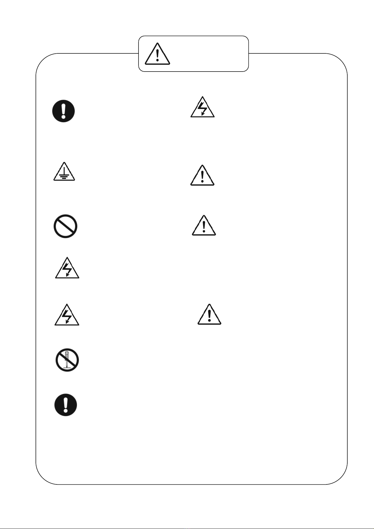
Safety Guidelines .............................................................................................4
Hazardous Area ...............................................................................................7
Electrically Live Area ....................................................................................................... 7
Machine Moving Area ...................................................................................................... 8
High Temperature Area .................................................................................................. 9
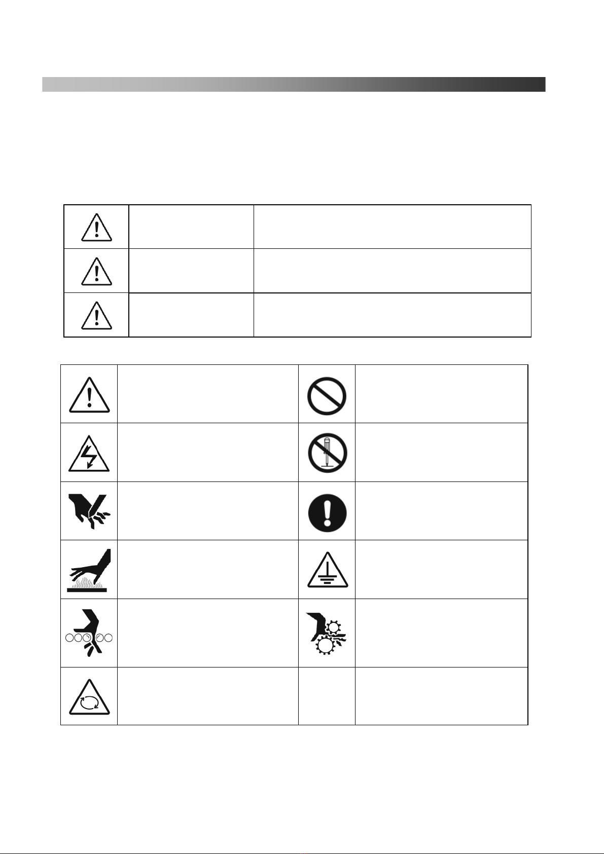
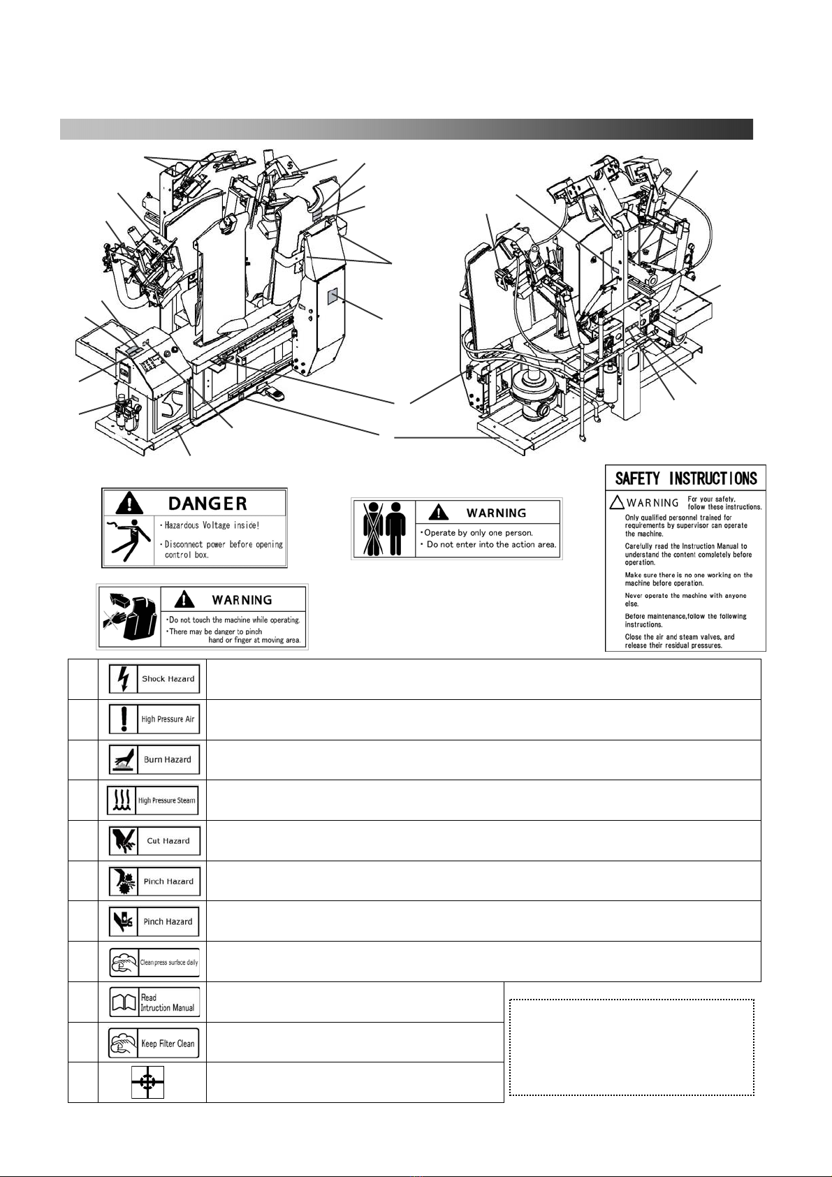
Safety Labels on the Machine.........................................................................10
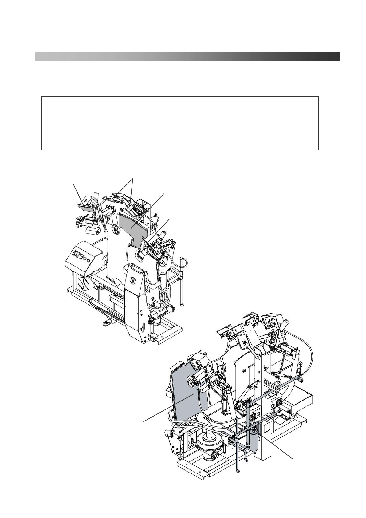
Main Devices..................................................................................................11
Control Unit...................................................................................................12
Control Box .......................................................................................................................... 12
Operation Box .................................................................................................................... 14
Operation Procedures ....................................................................................15
Provide Air ........................................................................................................................... 15
Provide Steam ..................................................................................................................... 16
Turn the Power On ........................................................................................................... 16
Press Warming Up Button..........................................................16
Set each timer according to the material of the shirt................17
Set the Shirt ......................................................................................................................... 18
After Operation Is Over ................................................................................................ 26
Other Operations...........................................................................................27
How to Reset Emergency Stop (Safety Error) ............................................. 27
About the Cover Counter .......................................................................................... 27
How to Replace the Cover & Padding.............................................................28
Tail Clamp ............................................................................................................................ 28
Body ......................................................................................................................................... 29
Neck Clamp ......................................................................................................................... 32
How to Install the Cuff Clamp Cover, Front & Rear Tuck Cover and
Short Sleeve Cover ........................................................................................................... 32
Test Operation ...............................................................................................33
Service Menu.................................................................................................36
Trouble Shooting............................................................................................42
DAILY MAINTENANCE............................................................................................................... 48
Check Item List .............................................................................................48
Check Item (Daily).........................................................................................49
Check Item (Monthly)....................................................................................51
Check Item (Annual)......................................................................................51
Item Check List .............................................................................................52
SPARE PARTS LIST ........................................................................................................................ 53
Motor Operation Diagram .............................................................................54
Air Piping (1).................................................................................................56
Air Piping (2).................................................................................................58
Air Piping (3).................................................................................................60
Steam Piping..................................................................................................62
Control Box・Switch Diagram.......................................................................64
Cover Diagram ..............................................................................................66
ATTACHED DIAGRAM ................................................................................................................ 68

4
Safety Guidelines
Warning labels are placed on the machine in order to prevent an operator and others from injury, and to ensure proper
and safe operation. For most parts, labels are placed on the operational area of the machine.
Use this product safely upon reading this manual and understand the warning labels on the machine.
Please keep this manual as it will be needed in the future.
■ Please read the description of each warning label below. Each sign shows the degree of risk of injury or damage if
the manual and/or labels are not followed and the machine is misused.
DANGER This indicates a potentially hazardous situation which, if not
followed, may result in death.
WARNING
This indicates a potentially hazardous situation which, if not
followed, may result in serious injury.
CAUTION This indicates a potentially hazardous situation which, if not
followed, may result in minor or moderate injury.
■Rules are shown in the table below.
General Sign (for Alertness)
This is to alert the user to unspecified caution,
warning or danger.
General Sign (for Prohibition)
This is to alert the user to unspecified
prohibition.
Shock Hazard
This is to alert the user to a risk of electric
shock in certain circumstances.
Prohibition of Dismantling
This is to alert the user to a risk of injury or
shock if the indicated part is dismantled.
Cut Hazard
This is to alert the user to a risk of cutting
hands or fingers by a cutter or others.
May cause physical handicap.
General Sign (for Compulsion)
This is to alert the user to unspecified user’s
action.
Burn Hazard
This is to alert the user to a risk of burn from
heat or steam.
Necessity to Ground
This is to indicate that the machine must be
properly grounded, using the attached green
wire.
Pinch Hazard
This is to alert the user to a risk of pinching
by rollers which may cause permanent
damage to extremities.
Rotation Hazard
This is to alert the user to a risk of injury if
rotating parts of the machine are not
properly covered with during maintenance
or operation.
Rotation Hazard
This is to alert the user to a risk of injury if
rotating parts of the machine are not properly
covered by during maintenance or operation.
Sankosha cannot be held legally responsible for any injuries to operators or damages to the machine caused by
alterations to the machine or operations not described in the machine manual.

5
■ Installation
Installation and rigging of this product
should be performed only by an authorized
Sankosha distributor or by qualified
personnel who has read this manual.
Improper installation or rigging of this machine
may result in shock, injury or burn.
■ Shock Hazard
Do not put a finger or metal into the machine
or Control Box.
It may cause electric shock or explosion.
■ Ground Connection
The green wire must be properly
grounded.
The electrical code must be conformed to
3 Phase 400V power.
Incorrect connection may cause electric shock.
■In case of flooding
Please call authorized personnel to inspect and
repair the machine if necessary.
It may cause electric shock.
■ Fire Hazard
Flammable articles such as gasoline, etc
should not be located near the machine.
It may cause fire or explosion.
■ Maintenance
Please call authorized service personnel.
Do not dismantle by yourself.
It may cause electric shock, injury, fire or
accident.
■ Shock Hazard
Do not touch the electric plug or switch.
It may cause electric shock.
■ Shock Hazard
Parts must not get wet when cleaning the
machine with water.
It may cause electric shock.
■Safety Instructions
・For your safety, please follow the
instructions below.
・ Only qualified trained personnel can operate the machine.
・ Carefully read this Instruction Manual in full before using
the machine.
・ Make sure there is no one working near the machine
before beginning operation.
・ The machine should be operated individually at all times.
・ Before conducting the proper maintenance, always keep
following instruction: close the air and steam valves and
release their residual pressures.
■ Alteration Hazard
Do not improve or dismantle the machine.
It may cause accident.
■ Do not Use During Disrepair
Turn the main power and breaker switches
off in case of malfunctions.
Call authorized service personnel.
It may result in injury or further damage to the
equipment.
WARNING

6
■Maintenance of warning labels
The labels need to be cleaned and replaced if necessary.
It may cause an accident.
■Inside use only
The machine must be located inside the facility.
Do not place it in a damp or wet area.
It may cause an accident.
■Not in use abroad
Do not use the machine outside of designated countries.
It may cause fire due to different electrical supply.
■Cleaning
Both the main power switch and the breaker should be off when cleaning.
It may cause electric shock without power-off.
■Check and cleaning
Electric plugs and electric sockets need to be checked and cleaned periodically.
If you find any damage, call us or your Sankosha distributor.
Breakage can cause electric shock and fire.
■Adequate space
Adequate space around the machine should be secured for service and maintenance.
Potential injury to service/maintenance personnel may result.
CAUTION

7
Hazardous Area
Electrically Live Area
DANGER
Control box has terminals with lethal voltage.
-Only maintenance personnel can open the box.
-Turn off the power before opening the box.
Ignoring this warning will result in serious injury or death due to electrical shock.

8
Machine Moving Area
WARNING
The machine has some moving areas along many portions.
Keep your hands away from the moving area during operation.
Before starting check up or maintenance, turn off the air and power first.
Ignoring this warning could result in serious injuries.
Around the Tuck Press Base
Around the Tuck Press and Shoulder Press Base
Around the Front Press
Transfer liner guide
Around the Rear Press Base

9
High Temperature Area
CAUTION
The machine has Press Heads which get extremely hot during operation.
Never touch Pressing surface during and for 30 minutes after the steam has been
turned off. Ignoring this warning may result in burns.
Front Press
Shoulder Press
Steam Piping
Tuck Press
Tuck Press
Rear Press

10
Safety Labels on the Machine
⑤ It may cause electric shock.
Before opening Control Box or maintenance, always turn the power off.
⑥ High pressure air!
Before maintenance, close air valve and drain residual pressure.
⑦ Surface is HOT!
Do not touch press head, steam piping and its surrounding area.
⑧ High pressure steam!
Before maintenance, close steam valve and drain residual pressure.
⑨ Cut hazard! Keep hands away from the designated area.
Turn the power off during maintenance or cleaning.
⑩ Pinch hazard! Keep hands away from the designated area.
Turn the power off during maintenance or cleaning.
⑪ Pinch hazard! Keep hands away from the designated area.
Turn the power off during maintenance or cleaning.
⑫ Clean pressing surface with cloth etc. every day.
⑬ Read Instruction Manual before operation.
⑭ Clean filter before operation.
⑮ Center Mark
Indicating the center of gravity of the machine.
⑦
⑥
①
②
Make sure that each warning label is
placed at the location shown above.
If any of the labels is missing,
damaged, or illegible, contact your
distributor to obtain a new one.
⑬
⑤
(
Inside Control Box
)
⑦
⑦
⑫
⑩
⑪
⑦
⑩
⑥
⑭
④
③
⑨
⑪
⑦
⑧
③ ②
④
①
⑮
⑩

11
Main Devices
Front
Back
Front Press
Steam Inlet
Blower Motor
Steam Gauge
Foot Pedal
Filter
Vacuum Motor
Body
Front Press
Safety Guard
Rear Press
Shoulder Press Safety Guard
Tuck Press
Tuck Press Safety Guard
Neck Clamp
Regulator
(Air Intake)
Control Box
Operation Panel
Cuff Set
Transfer
Steam Outlet
Short Sleeve Set
Operation Box
Tail Clamp
Solenoid Valve Box
Tuck Press
Tuck Press Safety Guard
Shoulder Press

12
Control Unit
Control Box
① Power Switch
The switch is for the main power.
Black button is for turning the Power ON. Red Button is for turning the Power OFF.
② Emergency Stop Button
Press this button at any stage in order to release the press and safely return it to the
original position.
The beep starts to sound when the Emergency Stop Button is pressed.
Release the lock by turning the pressed button clockwise. (The beep will stop.)
Press the reset button next to return to original position.
③ Reset Button
There are three functions dependent on different timing of button push.
1. Push this button to return to the previous position. If it is processed by foot pedal, it
is available before left the cuff set up.
2. To return to original position after Emergency Stop Button is activating.
3. To cease operation while the machine is working.
④ Long Timer Button (green lamp will flash when this timer is activated)
Let this button ON, you can change press timer with dialing No. 15 “Setting and Select
Dial”.
Also, this green lamp is blinking during operation if it is selected.
⑤ Short Timer Button (green lamp will flash when this timer is activated)
Let this button ON, you can change press timer with dialing No. 15 “Setting and Select
Dial”.
Also, this green lamp is blinking during operation if it is selected.
⑥ Steam Button (green lamp will flash when it is ON)
There are two functions.
1.For automatic operation, you can choose steam injection ON or OFF. When you push
it ON, it will steam during operation, and OFF it will not steam at all.
2.Press this button (over 1 second), Display (No.13) will show the steam timer setting
for automatic operation. You can change the timer with Dial (No.15) before timer
goes off from display.
⑪⑫⑮
⑭
⑬
②
⑩
⑤⑥
①
⑨ ⑧ ⑦
③
④

13
⑦ Size Adjustment Button (green lamp will flash when it is ON)
This button will make the sleeve arm position closer to the body when it is ON. It is
very useful if the short sleeve is too small to reach the original position.
⑧ Short Sleeve Button (green lamp will flash when it is ON)
Press this button ON to press a short sleeve shirt (not to work tuck press)
⑨ Warming-Up Button (green lamp will flash when it is ON)
Press this button ON prior to pressing a shirt; it will heat up the body. Please refer on
page 16 “Press warming-up Button”.
⑩ Enter Button (for Timer Remember) (green lamp will flash when it is ON)
This button is the registration button to remember all changes such as timer or
function.
⑪ Counter Clear Button
Press this button. "0" will blink at ⑬"Display Window". Press ⑩the "Enter Button".
You can reset the counter at "0". Press this button again. The window will show
garment counter.
⑫ Test Button (green lamp will flash when it is ON)
Press this button to start the test operation for each function. Please refer on page
33 “Test Operation”.
⑬ Display
It shows the counter, timer with count down, error number menu number and etc…
⑭ Power Lamp
The red lamp is blinking if it is turned on. Also, it is blinking with Emergency Stop
Button. It will flash and original position with reset button push.
⑮ Setting and Select Dial
This dial can change all timers and select menu numbers.

14
Operation Box
① Cuff Clamp Button
Press this button to clamp left cuff or short sleeve cuff. It must be complete up to tail
clamp operation. If you release the button before taking the next step, the clamp will
open.
② Start Button (right)
Press this button while also holding in the ①Cuff Clamp Button to work the shoulder
press and to move the front press head to the press position.
③ Start Button (left)
Press this button after selecting the long or short button and keep pressing either
button to work the front press and to start the automatic operation.
④ Long Button
There are two functions on this button.
1. This is for the long timer operation. The machine is working according to the
timer which is set in advance.
2. Press this button to clamp right cuff or short sleeve cuff. If you release the
button before taking the next step, the clamp will open.
⑤ Short Button
There are two functions on this button.
1. This is for the short timer operation. The machine is working according to the
timer which is set in advance.
2. Press this button to clamp right cuff or short sleeve cuff. If you release the button
before taking the next step, the clamp will open.
O
p
eration Box Left O
p
eration Box Ri
g
ht
⑤
①③
④
②

15
Run the machine where air can be supplied in a stable condition.
Use after-cooler or similar equipment to supply clean air at all times.
Operation Procedures
Provide Air
Check whether air pressure is set at the required
level for main regulator and other regulators as
below.
①MainRegulator ・・・0.6MPa
②Regulator (for Sleeve Down) ・・・0.25MPa
③Regulator (for Slide / Sleeve Up) ・・・0.3MPa
Low air pressure can cause a malfunction. If the pressure does not reach its standard
level, set the air pressure properly following the procedure below.
Check Point
Check compressor if the main air pressure does not reach 0.6MPa even after the
above adjustment
Follow the procedure for proper operation.
Improper operation can cause mechanical failure or injury to operators.
■ How to adjust air pressure
1. Pull the adjustment knob up.
2. Turn the knob to adjust air pressure
Clockwise →Pressure will increase
Counterclockwise →Pressure will decrease
3. Push the knob down.
②
①
Attention!
③
Caution

16
Provide Steam
Check whether steam with the pressure at 0.6MPa or more can be supplied to the machine.
If the steam pressure does not reach required level, it may adversely affect shirt
finishing quality. Always check whether the steam pressure meets its requirement.
It takes about 15 minutes until press heads heat up after steam is injected.
(It may vary depending on the season and the environment.)
Insufficient heat may adversely affect shirt finishing quality.
Turn the Power On
The power is ON by pressing black button at
the side of the control box.
→The power lamp at control panel is blinking,
and show “- - - -“on display.
Press “Reset” button.
→The lamp will keep lit and it is available to operate.
Also, the display will change to counter.
・Any operation is not available without pushing the Reset button.
・In case of the front press not being at original position, it will then move to
its original position.
(“A03” will be displayed during the move.)
Press Warming Up Button
Press the “Warming-up” button on the control panel. It will work the blower motor
30 seconds ON and OFF for 10 minutes to warm up the machine.
Press “Reset” button (blue) or “Warming –Up” button to finish the warming up process.
Caution
Warming-Up Button

17
Set each timer according to the material of the shirt
How to set Long Timer / Short Timer
① Press Long Timer button or Short Timer button. (either button which is selected lamped)
・When you choose long cycle timer, you can change timer for long cycle.
・・・it shows current long cycle timer on display.
・When you choose the short cycle timer, you can change the timer for the short cycle.
・・・it shows current short cycle timer on display.
② Turn the “Setting and Select Dial” to change timer. You can change per second.
*If you turn counterclockwise, the timer will increase. If you do clockwise, the timer
will decrease.
③ Press the “Enter” button to set the timer →the new time will be memorized.
Press the same timer button not to memorize the timer →the timer will be the same as
the original.
(However, the changed timer will be effective as long as machine is ON. )
It is set 20 seconds on short timer and 28 seconds on long timer as standard.
(Max. 99 seconds)
How to set the Steam Injection Timer
① Press the “Steam” button until showing the steam timer on the display (about 1 second)
(green lamp is ON)
② Turn the “Setting and Select Dial”, you can change the timer per second.
*If you turn counter clockwise, the timer will increase. If you do clockwise, the timer
will decrease.
④ Press the “Enter” button to set the timer→the new time will be memorized.
⑤ Press the same timer button not to memorize the timer →the timer will be the same as
the original.
③ (However, the changed timer will be effective as long as machine is ON. )
It is set 3.8 seconds on standard. (Max. 9.9 seconds)
Lon
g
Timer
Dis
p
la
y
Short Timer
Setting and Select Dial
Enter
Dis
p
la
y
Steam Button
Setting and Select Dial
Ente
r

18
・Beware of pinching hands or garment by moving part during the
operation.
・Please take precautions against burning yourself at metal parts of press
Set the Shirt
・There are tips on how to finish the garment very well at each process.
・Please read and understand these tips, and utilize them for daily operations.
・Please also read the caution statements for the safety use of the machine.
Set the Shirt on the Body
By finishing setting the shirt within 25 seconds, this will prevent the shirt from
airing out too much and the pressing quality will improve.
Please aim to complete the setting the shirt within 25 seconds.
Set the shirt right and
left equally.
①Make sure that back side of
the collar is firmly touching
the stainless collar.
②
T
Ti
ip
ps
s!
!
T
Ti
ip
ps
s!
!
Gap
CAUTION

19
Set the Neck
Set the neck and step on the Foot Pedal.
→The Neck Clamp will close.
※If you want to set the neck again, press the Reset Button (blue).
The Neck Clamp will open, and you can set the neck once again.
※In order to set the neck after the tail of shirt is set, step on the Foot Pedal. The Neck
Clam
p
o
p
ens while ste
pp
in
g
on the Foot Pedal.
The line of shirt should be
along
Hold down with
index finger…..and lift the shirt
slightly up.
Overlap the right side with
the left side.
Set left (button) side
⑤
③④
⑥
T
Ti
ip
ps
s!
!
Set the right (button hole) side

20
Set the Tail
After smoothing out the back of the shirt from top to bottom with both hands, step on
the Foot Pedal and pull the tail at the same time.
→The Tail Clamp closes, and the vacuum starts to work.
※If you want to set the tail again, press the Reset Button (blue).
The Tail Clamp opens, and you can set the tail once again.
Remove air by smoothing out
from top to bottom with palms.
After removing the air completely,
hold the tail by both hands. Step
on the Foot Pedal while pulling the
shirt down and stretching right
and left at the same time.
Do not let go of the shirt
until the Tail Clamp closes.
⑦⑧
⑨
T
Ti
ip
ps
s!
!
Table of contents
Other Sankosha Power Tools manuals
Popular Power Tools manuals by other brands

MasterCraft
MasterCraft 054-1266-4 owner's manual

Mannesmann Demag
Mannesmann Demag RRI-50T operating manual

Tuthill
Tuthill D Series Installation and service instructions

Metabo HPT
Metabo HPT KM 12VC Safety instructions and instruction manual

Marson
Marson BT-2 Instruction Manual for Operation

Jet
Jet JDP-2800VS operating instructions