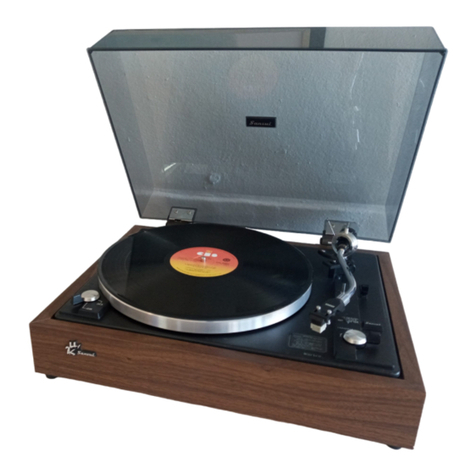
Sansui P-M7 User manual

oe
OMAT.
ie

1.
BLOCK
DIAGRAM
Terminal
MB884
1-566M)
36
fO3
B
Sensor
1LD2
“=e
K
f06
Isnal
>
al
K
1
C
Sensor
f{LO3
Za
O7
_
i3
2
pb
U
Sensor
uP
=
>
D
Sensor
o-o
DOWN
_
Micro
Switch
Sensor
Sensitivity
Selection
Micro
Computer
f1C3
MB884)
-
566M
aul
i
Computer
+5V
+5V
Editing
QL
Ind
fQ
gLDe
”
'
bs
t{
gLDi}/
Music
ty
>
iy
s
Selection
nd
4
fC
107]
7
|
'
gi
De
1
Nay
i
Repeat
Ind
|
fie)
i)
CPU
ind
fO1
gLDIo
Normal
Speed
Select
33%
rpm
50H2
45rpm_)—
67
SHz
|
SSD-1_MOTOR
CONTROL
Driving
Tone
Arm
Vertically
Driving
Tone
Arm
Horizontally
Analog
Switch
TC9I24P
PLL

P-M7
2.
OPERATIONS
(see
Fig.
2-1,
Fig.
2-2,
Fig.
2-3,
Timing
Chart
and
Block
Diagram)
This
fully-automatic
player
is
of
the
linear
tracking
arm
type,
being
provided
with
the
following
various
functions:
1)
automatic
random
music
selection
(seven
musics);
2)
automatic
record
disc
size
selection
(30cm-
25cm-and
17cm-dia.
discs);
3)
automatic
speed
selection
according
to
disc
sizes
(33
1/3
rpm
and
45
rpm);
and
4)
computer
editing
in
cooperation
with
a
cassette
deck
(D-M7,
SC-A33,
D-570,
and
D-370).
2-1.
Fully-automatic
System
Outline
This
fully-automatic
system
player
comprises
1)
an
automatic
mechanism
for
driving
a
tone
arm
horizontally
and
vertically
and
2)
a
control
section
for
electrically
contro!
the
automatic
mechanism.
The
automatic
mechanism
assembly
includes
tone
arm
position
sen-
sors
(A,
B
and
C
sensors),
lifter
position
sensors
(UP
and
DOWN
sen-
sors),
an
arm
servo
sensor,
and
an
automatic
disc
size
selection
sen-
sor
(E
sensor)
and
an
automatic
music
selection
sensor
(F
sensor)
both
mounted
on
the
tip
of
the
cartridge,
in
addition
to
the
auto-
matic
mechanism,
in
order
to
detect
the
conditions
of
the
tone
arm.
The
control
section
includes
a
microcomputer
MB
8841-566M
and
its
peripheral
circuits,
in
order
to
control
1)
start/stop
of
a
DD
motor,
2)
lead-in,
lead-out,
return, repeat,
and
up-and-down
move-
ment
of
the
tone
arm,
and
3)
automatic
disc
size
selection,
auto-
matic
music
selection
and
automatic
disc
speed
selection,
in
re-
sponse
to
each
output
signal
outputted
from
each
sensor.
2-2.
Automatic
Mechanism
Assembly
Operation
1.
Inorder
to
drive
the
automatic
mechanism
assembly,
that
is,
to
drive
the
tone
arm
horizontally
for
tone
arm
lead-in
and
lead-out
operations,
the
revolution
power
of
the
micromotor
(I)
is
trans-
mitted
through
a
belt
(A),
a
warm
gear
(A)
a
drive
gear,
and
a
wire.
2.
In
order
to
drive
the
tone
arm
vertically
for
tone
arm
up-and-
down
movement,
the
revolution
power
of
the
micromotor
(Il)
is
transmitted
through
a
belt
(B),
a
warm
gear
(B),
a
lifter
cam,
and
a
lifter
plate.
The
tone
arm
is
driven
vertically
by
moving
up
and
down
an
arm
holder
weight
mounted
on
an
arm
shaft.
2-3.
Each
Sensor
Function
For
Fully-automatic
Operation
:
A.
A
Sensor,
B
Sensor,
and
C
Sensor
As
shown
in
Fig.
2-2,
the
A,
B,
and
C
sensors
detect
tone
arm
posi-
tions
required
for
automatic
operation
in
such
a
way
that
three
phototransistors
(fQ5,
fQ6
and
fQ7)
are
turned
on
or
off
whenever
a
position
guide
moves
between
three
phototransistors
mounted
on
a
sensor
holder
and
covered
by
a
slit
plate
and
three
LEDs
(fLD1,
fLD2
and
fLD3).
The
A
sensor
detects
the
lead-in
positions
of
30cm-,
25cm-,
and
17cm-dia.
discs
and
the
lead-out
position
of
a
17cm-dia.
disc.
Fur-
ther,
the
B
sensor
and
the
C
sensor
detect
in
combination
the
disc
size
selection
positions
of
30cm-,
25cm-,
and
17cm-dia.
discs.
The
B
sensor
detects
the
lead-out
positions
of
30cm-
and
25cm-dia.
discs
and
the
positions
required
for
operating
the
automatic
music
selection
sensor
(E2
sensor).
That
is
to
say,
when
the
E2
sensor
detects
some
lead-over
groove
while
the
B
sensor
is
kept
turned
on
(in
this
case
the
input
port
pin
No.
27
of
the
microcomputer
is
at
a
L-voltage
level),
the
tone
arm
stops
and
begins
to
come
down.
The
C
sensor
detects
the
disc
size
selection
position
of
a
17cm-dia.
disc
in
combination
with
the
A
sensor.
B.
UP
(U)
Sensor
and
DOWN
(D)
Sensor
The
U
sensor
and
D
sensor
are
made
up
of
a
lifter
cam
and
two
microswitches.
The
U
sensor
detects
the
up-position
of
the
tone
arm,
and
the
D
sensor
detects
the
down-position
of
the
tone
arm.
When
the
U
sensor
or
D
sensor
detects
the
up-
or
down-position
of
the
tone
arm,
the
terminal
of
each
microswitch
is
grounded.
C.
E
Sensor
and
F
Sensor
Being
mounted
on
the
tip
of
the
cartridge,
the
E
sensor
and
F
sensor
supply
three
signals
required
for
automatic
disc
size
selection
and
automatic
music
selection
to
the
microcomputer,
after
having
di-
vided
the
output
signals
into
E2,
E3
and
F2
signals
through
an
elec-
tric
circuit.
@
£2
signal
The
E2
signal
is
a
music
number
counting
signal
required
for
moving
down
the
tone
arm
at
a
desired
music
position
during
the
automatic
music
selection
operation.
When
the
E
sensor
detects
a
desired
lead-
over
groove
and
the
E2
signal
is
generated
(changes
to
a
H-voltage
level)
(in
this
case,
the
input
port
pin
No.
33
of
the
microcomputer
changes
to
a
L-voltage
level),
the
tone
arm
stops
moving
horizontally
and
next
begins
coming
down.
Arm
Shaft
Bearing
Fig.
2-1
Wire
=>
¢z=
yr
y
se
=
7
@
©
in}
Drive
Gear
$2
Auto
Mechanism
Ass‘y
Position
Guide
Warm
GearlA)
Belt(A)
a]
|
[
A,B,C
Sensor
$-01
12105106
07)
Sht
Plate
Asia)
|
Guide
$-011
11101
.f102.1103)
Fig.
2-2
Warm
Gear(8)
D
Sensor
Micro
SW.
Lifter
Cam
Sensor
Holder
E,
F
Sensor
LI

P-M7
e@
£3
signal
The
E3
signal
is
a
signal
to
detect
the
size
and
the
presence
or
ab-
sence
of
a
disc.
In
the
tone
arm
lead-in
operation,
if
the
E3
signal
is
generated
(changes
from
a
L-voltage
level
to
a
H-voltage
level)
(in
this
case,
the
input
port
pin
No.
4
of
the
microcomputer
changes
from
a
H-voltage
level
to
a
L-voltage
level)
when
the
A,
B
and
C
sensors
are
generating
the
respective
signals
as
depicted
within
the
zones
(A)
®)
and
©
shown
in
Fig.
2-3,
the
respective
disc
sizes
of
30cm,
25cm
and
17cm
are
selected.
After
the
E3
signal
has
been
generated
within
the
zones@,®)and©
shown
in
Fig.
2-3,
the
tone
arm
stops
moving
horizontally
and
next
comes
down
when
the
A
sensor
generates
a
L-voltage
level
signal
(in
this
case,
the
input
port
pin
No.
26
of
the
microcomputer
changes
to
a
H-voltage
level)
or
a
H-voltage
jevel
signal
(in
this
case,
the
input
port
pin
No.
26
of
the
microcomputer
changes
to
a
L-voltage
level).
Further,
in
the
case
where
no
E3
signal
is
generated
within
the
zones@,®
and
©
it
is
determined
that
there
is
no
disc
on
the
turntable.
@
F2
signal
Being
different
from
the
E2
and
E3
signals,
the
F2
signal
is
a
signal
to
indicate
that
the
F
sensor
detects
a
lead-over
groove
when
the
stylus
is
tracing
a
music
ona
record
disc.
The
F2
signal
serves
as
follows:
The
fead-over
groove
of
each
music
is
detected
in
the
automatic
music
selection
operation.
In
the
case
where
the
last
music
ona
re-
cord
disc
is
selected,
the
instant
the
last
lead-over
groove
(lead-out
groove)
is
detected,
the
F2
signal
changes
from
a
L-voltage
level
to
a
H-voltage
level
(in
this
case
the
input
port
pin
No.
33
of
the
micro-
computer
changes
to
a
L-voltage
level,
so
that
the
tone
arm
begins
to
return.
Fig.
2-3
Position
Guide
A
SENSOR
B
SENSOR
C
SENSOR
B
SENSOR
|
27
C
SENSOR
|
28
E3
SENSOR
|
4
Selection
Z
Selection
77cm
Zone Zone
Selection
Zone
17cm
Play
30cm
Play
D.
Arm
Servo
Sensor
While
the
stylus
is
tracing
a
music
on
a
disc,
it
is
necessary
for
the
stylus
to
be
in
contact
with
the
disc
at
a
right
angle
to
the
modu-
lated
glooves
formed
in
the
disc.
The
arm
servo
sensor
detects
stylus
inclination
from
a
right
angle
to
the
modulated
grooves,
while
the
stylus
moves
on
a
disc.
The
incli-
nation
angle
of
the
stylus
is
checked
by
a
photo
interaptor
of
the
arm
shaft
bearling
and
two
photo
couplers
(fQ8
and
fQ9).
When
the
stylus
inclines
from
the
right
angle,
the
photocoupler
fQ8
or
fQ9
is
turned
on
according
to
the
direction
in
which
the
stylus
inclines,
in
order
to
activate
the
analog
switch
f1C6.
In
response
to
the
signals
from
the
photocouplers,
the
micromotor
(il)
rotates
clockwise
or
counterclockwise
in
order
to
control
the
tone
arm
so
as
to
be
in
contact
with
the
modulated
groove
at
a
right
angle.
E.
Music
Selection
Sensitivity
Switching
Circuit
The
automatic
music
selection
operation
must
be
accurate,
without
producing
any
positioning
error
when
moving
down
the
tone
arm
onto
a
disk,
even
if
there
are
various
dimensions
in
the
width
of
lead-over
groove.
This
music
selection
sensitivity
switching
circuit
can
adjust
the
sen-
sitivities
of
the
E2
and
F2
signals
at
the
same
time.
As
shown
in
the
block
diagram,
the
reference
voltage
applied
to
the
comparator
is
adjusted
to
three
stages
by
using
a
sensor
sensitivity
selector
switch.
2-4.
Microcomputer
Output
Peripheral
Circuits
A.
Micromotor
control
circuit
1.
Operation
of
tone
arm
horizontally
driving
micromotor
(1)
The
micromotor
operates
according
to
the
tone
arm
up:
or
down-condition
as
follows:
@
Where
the
tone
arm
is
up;
When
the
pin
No.
22
of
the
microcomputer
becomes
a
L-voltage
level,
the
micromotor
(1)
rotates
counterclockwise
to
perform
the
lead-in
operation.
On
the
other
hand,
when
the
pin
No.
23
of
the
microcomputer
becomes
a
L-voltage
level,
the
micromotor
(I)
rotates
clockwise
to
perform
the
lead-out
operation.
@
Where
the
tone
arm
is
down;
When
the
tone
arm
is
in
a
down-state,
the
micromotor
(1)
rotates
clockwise
or
counterclockwise
in
response
to
the
output
signal
from
the
arm
servo
sensor
(fQ8
and
fQ9)
to
control
the
tone
arm.
Further,
when
the
tone
arm
is
down
(in
playing
a
music),
since
the
pins
No.
6
and
No.
12
of
the
analog
switch
become
a
L-
voltage
level,
the
micromotor
(1)
does
not
rotate
in
response
to
the
output
signal
from
the
pins
No.
22
and
No.
23
of
the
micro-
computer.
2.
Operation
of
tone
arm
vertically
driving
micromotor
(I)
When
the
pin
No.
24
of
the
microcomputer
becomes
a
L-voltage
level,
the
micromotor
(I)
rotates
counterclockwise
to
move
the
tone
arm
up
or
down.
If
the
UP/DOWN
key
is
depressed
while
the
tone
arm
is
moving
up
or
down,
the
pin
No.
25
of
the
micro-
computer
becomes
a
L-voltage
level
and,
therefore,
the
micro-
motor
(II)
rotates
clockwise
to
move
the
tone
arm
up
or
down.
B.
33
1/3
and
45
rpm
Automatic
Selection
Circuit
According
to
the
size
of
a
disc,
the
revolution
speed
(33
1/3
or
45
rpm)
of
the
turntable
is
automatically
determined.
When
the
E3
sensor
detects
a
30cm-
(25cm-}
dia.
disc
and
a
17cm-dia.
disc,
the
pin
No.
20
of
the
microcomputer
outputs
a
L-voltage
level
signal
for
the
30cm-
(25cm-)
dia.
disc,
and
a
H-voltage
level
signal
for
the
17cm-dia.
disc.
This
output
signal
is
inputted
to
the
pin
No.
10
of
the
DD
motor
control
IC
(TC
9142P
:
elC1)
via
the
speed
selector
switch
(fS2).
The
turntable
rotates
at
a
speed
of
33
1/3
rpm
when
the
pin
No.
10
of
elC1
is
at
a
L-voltage
level,
and
at
a
speed
of
45
rpm
when
the
pin
No.
10
of
elC1
is
at
a
H-voltage
level.
The
relationship
between
the
speed
selector
switch,
the
record
disc
size,
and
the
revolution
speed
is
listed
in
the
following
table:
SPEED
SELECTOR
RECORD
SIZE
Sw(fS2)
30,
25cm-dia.
|
17cmrdia.
MB8841
Pin
No.
20
H
NORMAL
TC9142P
Pin
No.
10
|
H
Speed
(rpm)
|
wB3e4i
Pin
No.
20
INVERSE
TC9142P
Pin
No.
10
Speed
(rpm)

C.
DD
Motor
Control
Circuit
If
the
START/STOP
switch
is
depressed
when
the
turntable
stops,
a
L-voltage
level
signa!
is
outputted
from
the
pin
No.
19
of
the
micro-
computer
and
is
inputted
to
the
pin
No.
11
of
the
DD
motor
control
IC
(TC9142P),
When
a
L-voltage
level
signal
is
inputted
to
the
pin
No.
11,
the
turntable
rotates.
D.
Music
Selection
Indicator
Circuit
In
the
automatic
music
selection
operation,
the
selected
musics
are
stored
into
the
microcomputer
and
displayed
on
the
indicator.
In
playing
a
music,
the
indicator
light
blinks
as
follows:
When
the
tone
arm
lead-in
operation
stops
in
a
modulated
groove,
the
indicator
light
begins
to
blink
the
instant
a
lead-over
groove
is
detected
(the
F2
signal
changes
from
a
L-voltage
level
to
a
H-voltage
level).
Further,
when
the
tone
arm
stops
in
a
lead-over
groove,
the
indicator
light
begins
to
blink
the
instant
the
micromotor
(II)
stops.
Furthermore,
in
continuously
playing
musics,
the
indicator
light
begins
to
blink
the
instant
a
lead-over
groove
is
detected
(the
F2
signal
changes
from
a
L-voltage
level
to
a
H-voltage
level).
E.
Computer
Operation
Indicator
Circuit
The
output
signal
from
the
pin
No.
17
of
the
microcomputer
turns
on
or
off
the
fQ1,
so
that
the
indicator
light
blinks.
The
indicator
light
blinks
during
the
micromotor
(1)
or
(II)
is
ro-
tating.
However,
in
case
of
such
a
miss-programming
that
only
one
music
number
not
included
in
a
record
disc
is
selected
or
in
case
of
no
record
disc,
the
indicator
blinks
much
faster
then
its
of
normal
operation
after
the
return
operation
begins.
®
MICRO
COMPUTER
Timing
chart
1
AUTO
MUSIC
SELECTION
2-3-5
(30cm,
33
rpm)
MICRO
COMPUTER
MB8841-566M
AUTO
MUSIC
SELECTION
2-3-5(30cm,
33rpm)
MUSIC
SELECTION
(2-3-5)—*LEAD
IN(
1
)—>PLAY2—>
P-M7
F.
Muting
Circuit
The
muting
circuit
is
a
circuit
to
short-circuit
the
output
signal
from
the
player,
where
necessary.
The
muting
operation
is
performed
by
using
the
output
signal
from
the
pin
No.
18
of
the
microcomputer.
1)
tn
the
automatic
disc
size
selection
and
the
UP/DOWN
key
de-
pression,
the
muting
is
off
when
the
tone
arm
is
down,
and
is
on
when
the
tone
arm
is
up.
In
the
automatic
music
selection
operation
(See
Timing
Chart),
the
muting
is
off the
moment
the
tone
arm
moves
down
com-
pletely
after
the
lead-in
operation
(the
micromotor
(Il)
stops
rotating
counterclockwise).
Further,
when
the
stylus
moves
down
onto
a
modulated
groove,
the
muting
is
off the
moment
the
F
sensor
detects
a
lead-over
groove
(the
F2
signal
changes
from
a
H-voltage
level
to
a
L-
voltage
level).
2
—
G.
Computer
Editing
Circuit
In
the
same
way
as
in
the
muting
circuit
of
the
player,
the
computer
editing
operation
is
performed
by
connecting
the
output
signal
from
the
pin
No.
18
of
the
microcomputer
to
the
pause
circuit
of
a
cassette
tape
recorder
through
a
AND
circuit.
This
circuit
controls
the
recording
on-or-off
operation
on
the
cassette
tape
recorder
side
in
accordance
with
the
automatic
operation
on
the
player
side.
in
other
words,
when
the
muting
on
the
player
side
is
on
(the
pin
No.
18
of
the
microcomputer
is
at
a
L-voltage
level),
the
pause
on
the
cassette
deck
side
is
on;
when
the
muting
on
the
player
side
is
off
(the
pin
No.
18
is
at
a
H-voltage
level),
the
pause
on
the
cassette
deck
side
is
off.
Tess
Ie
Parmer
eee
ST
ARSENE
|
INPUT/OUTPU
PIN
No.
—PLAY3—>CUT
(UP/DOWN)
->PLAYS—>LEAD
OUT
Iga
LTO
FTA
Oo
pat
A
<=
|
ES
Ra
|
26
BS
Rs
27
c
Re
|
28
U
R7
|
29
SENSOR
}|——+——_]
D
|
Re
|
30
is
E2
|
Tc
|
8
—
&
E3
IRQ
4
30cm
Selection
UP/DOWN
SW.
_|
Ris,
K2|
35,
40
}
tL
Ube
Hoown
Ris,
K2|
37,
MUSIC
2."
[Risse
92,40:
_
oa
eae
a
SELECTION}
3
|Ris,
K:|
37,39
|
|
Sw.
7
5
Ria,
Ko]
36,
38
ey
a
Se
BZ
y
|
a)
MOTOR(I)
|
cow
|
Ro
|
22
||
MICRO.
|
cw
|
R
25
i
MOTOR
(II)
iz
|
(|
(Lifter)
CCW
|}
Ra
24
OOWN
uP uP
DOWN
uP
bb
START
BOWN
5
[DDMOTOR
Jerop
|
Os
|
19
ia
|_|
2
MUTING
Os
|
18
ON
OFF
Fon
[FL
ow
_|
OFF
ON
SPEED
33/45rpm.
|
Or
|
20
L
bet
nee
P|
io)
bee
ss
§@H
Weems
TT
——
ee
2
SELECTION
Pe
|
il
[n/n
i
3
3
ar)
ERE

P-M7
@
MICRO
COMPUTER
Timing
chart
2
AUTOMATIC
RECORD
SIZE
DETECTOR
(17cm,
45
rpm)
AUTOMATC
RECORD
SIZE
DETECTOR
MICRO
COMPUTER
MB8841-566M
(izem
--45rpne)
St
ta
|
Arm
Rest
INPUT/OUTPUT
PORT
|PIN No.)
17cm
LEAD
IN-PLAY->REPEAT—>CUT—
RETURN
Point
AB
Ra
26
|
27
28
SENSOR
17cm
Selection
17cm
Selection
[
START/STOP
SW
|Ko.
Rial
38,
34
T
REPEAT
SW
Ka,
Ria|
41,
35
Ri
Micro
Motor
(I
)
LEAD
IN
Micro
Motor
(II
)
(Lifter)
SPEED
33/45rpm
REPEAT
IND.
DD
MOTOR
$ct8T
OUTPUT
Lighted
®
MICRO
COMPUTER
Timing
chart
3
MANUAL
RECORD
SIZE
DETECTOR
(17cm,
45
rpm)
MANUAL
RECORD
SIZE
DETECTOR
MICRO
COMPUTER
MB8841-566M
(17em_
45rpm)
INPUT/OUTPUT
PORT
|PINNo.)
17cm
LEAD
IN(MANUAL)—>PLAY—>
CUT
PLAY>LEAD
OUT—
RETURN
Re
28
R7
29
Re
30
SENSOR
IRQ
4
7cm
Selection
START/STOP
SW
|
Ko,
Ri2j
38,
34
UP/DOWN
SW
Ka,
Ris}
40,
35
MANUAL
<4
SW
Ki,
Ri3|
39,
35
MANUAL
®
SW
Ko,
Ri3|
38,
35
Micro
RETURN
Motor
(I
)
Micro
R3
Motor
(II
)
(Lifter)
[oo
moToR
Eis
MUTING
SPEED
33/45rpm

3.
ADJUSTMENTS
Note:
Before
adjustments
of
3-1
and
3-2,
remove
the
arm
rest
only.
3-1.
Adjustment
of
Automatic
Disk
Size
Selection
Operation
(See
Figs.
3-1,
3-3
and
3-4)
1)
By
using
30cm
size
record,
actually
carry
out
the
automatic
disk
size
operation
(lead-in
operation).
Adjust
the
lead-in
adjusting
cam
(See
Fig.
3-4)
by
the
tone
arm
placed
on
the
arm
rest
(the
Position
@
as
shown
in
Fig.
3-3
so
that
the
stylus
tip
may
come
down
to
the
position
(the
lead-in
groove
position)
146
mm
away
from
the
disk
center
(See
Fig.
3-1).
By
using
17cm
size
record,
actually
carry
out
the
automatic
disk
size
operation
(lead-in
operation).
Confirm
that
the
stylus
tip
may
come
down
to
the
lead-in
groove
position.
i)
—
Fig.
3-1
Cartridge
wer
Disc
Pea
es
46mm
3-2.
Adjustment
of
Automatic
Music
Selection
Operation
(See
Figs.
3-2,
3-3
and
3-4)
@
Required
disc
and
measuring
instruments
1)
Tester
(DC
voltmeter)
Input
impedance:
50kohm/V
or
more.
(The
higher,
the
better)
2)
A
vinyl
chloride
record
disc
without
grooves
or
with
wider
lead-
out
spiral
than
usual.
3)
Arule
with
graduation
marks
starting
from
the
edge.
A.
Tone
Arm
Height
Adjustment
Adjust
the
stylus
and
disk
as
shown
in
Fig.
3-2,
by
rotating
the
tone
arm
height
adjusting
screw
(See
Fig.
3-4)
to
the
position
@)
as
shown
in
Fig.
3-3.
(Stop
the
stylus
at
a
position
about
130
mm
away
from
the
disk
center.)
Fig.
3-2
wi
Disc
without
grooves
Disc
with
grooves
!
eceereyeUuN
|
Lead-out
groove
Fig.
3-4
Tension
Adjusting
Screw
Make
two(2)
turns:
around
this
P-M7
B.
Sensitivity
adjustment
of
E
and
F
sensor
1.
Setting
At
the
tone
arm
position,
in
case
of
a
record
disc
without
grooves,
stop
the
stylus
at
a
position
about
10
cm
away
from
the
disc
center.
In
case
of
a
record
disc
having
grooves,
stop
the
stylus
above
the
flat
surface
nears
10
cm
away
from
the
disc
center.
2.
How
to
adjust
(See
Fig.
3-3,
Top
View
on
Page
8)
a)
Connect
the
DC
voltmeter
across
the
test
terminal
E
and
G
(ground)
and
then
adjust
the
voltage
to
DC
1V
by
rotating
the
volume
(fVR1)
<E
sensor
adjustment>
Connect
the
DC
voltmeter
across
the
test
terminal
F
and
G
(ground)
and
then
adjust
the
voltage
to
DC
1V
by
rotating
the
volume
(fVR2)
<F
sensor
adjustment>
Note:
When
adjusting
both
the
sensors
with
the
stylus
stopped
on
a
lead-over
groove
of
an
ordinary
record
disc,
note
that
there
is
a
difference
in
detection
position
between
E
sensor
(leading
sensor)
and
F
sensor.
b
—
C.
Level
adjustment
of
F2
signal
1.
Setting
Set
the
stylus
in
the
same
way
as
described
under
Section
2,
and
then
move
the
tone
arm
downward.
(Check
that
the
stylus
stays
ona
lead-over
groove.)
2.
How
to
adjust
(See
Fig.
3-3,
Top
View
on
Page
8)
a)
Connect
the
DC
voltmeter
across
test
terminal
Fz
and
G
(ground)
and
then
adjust
the
voltage
to
DC
1V
by
rotating
the
volume
(fVR3).
Fig.
3-3
Tone
Arm
Height
Adjusting
Screw
Lead-In
Adjusting
Screw
Test
Terminal
Arm
Servo
Adjusting
Cam
Sensor
Holder
Fastening
Bolt
‘Tone
Arm
Height
Adjusting
Screw
Lead-In
Adjusting
Cam

P-M7
D.
Delay
adjustment
of
E,
signal
1.
Setting
Use
the
record
disk
in
which
many
musics
(about
seven
music
tracks)
are
recorded,
and
select
three
music
tracks
having
lead-over
grooves,
respectively,
near
positions
70mm,
100mm,
and
130mm
away
from
the
disc
center.
2.
Adjustment
(See
Fig.
3-5,
Top
View
on
Page
8)
Perform
the
respective
lead-in
operations
for
three
selected
music
tracks,
and
adjust
the
operations
by
rotating
the
volume
(fVR4)
as
shown
in
Fig.
3-3
so
that
the
stylus
comes
down
on
or
a
little
before
the
lead-over
grooves
for the
three
music
tracks.
If
the
volume
(fVR4)
is
rotated
clockwise,
the
lift-down
position
of
the
stylus
is
shifted
inward.
Note:
In
the
lead-over
grooves
existing
on
a
70mm-or-less
from
the
center,
the
misplacing
of
the
arm
in
detection
position
occurs
inevitably.
Fig.
3-5
Cartridge
Disc
5/4
3
2)
!
7,6
Jom
——--|
10cm
13cm
Note:
Remove
the
cabinet
before
adjustments
of
3-3
and
3-4.
How
to
remove
the
cabinet.
(See
Top
View
on
Page
8)
Unscrew
seven
cabinet-mounting
screws
on
the
bottom
of
the
chassis,
Remove
the
E-ring
fixing
the
turntable
to
the
spindle
of
the
motor.
3)
Remove
the
player
case
cover.
4)
Move
the
tone
arm
to
the
player
case
cover
Position
by
depress-
ing
the
MANUAL
key
(
4
),
before
removing
the
cabinet.
3-3.
Arm
Servo
Adjustment
(See
Fig.
3-4,
Fig.
3-6)
A.
Setting
1)
Move
the
tone
arm
leftward
and
stop
it
within
the
record-play-
able
range
by
depressing
the
MANUAL
key
(
>
).
2)
Move
the
tone
arm
downward
by
depressing
the
UP/DOWN
key.
B.
Adjustment
1)
Loosen
the
sensor
holder
fastening
bolt,
and
adjust
the
arm
servo
adjusting
cam
so
that
the
tone
arm
does
not
move
in
either
direc-
tion,
in
the
state
where
the
tone
arm
is
in
the
down
position.
-e@
—
2
—
2)
After
adjustment,
check
that
the
voltage
across
the
connector
terminals
No.
9
or
TP6
and
GND
of
S-0107
(across
the
terminals
of
the
micromotor
(I)
is
within
OV
+1V
when
the
sensor
holder
fastening
hexagon
bolt
is
fastened.
3)
Check
that
the
tone
arm
will
not
move
in
either
direction
when
the
UP/DOWN
key
is
depressed
repeatedly.
Fig.
3-6
Arm
Servo
Adjusting
Cam
Sensor
Holder
Fastening
Bolt
3-4.
Tension
Adjustment
of
Tone
Arm
Horizontally
Driving
Wire
(See
Fig.
3-4)
Move
the
tone
arm
by
depressing
the
MANUAL
key
and
adjust
the
tension
adjusting
screw
so
that
the
wire
does
not
slip
along
the
driv-
ing
gear.
Note:
Care
must
be
taken
not
to
fasten
the
tension
adjusting
screw
too
tightly.
®
Variable
resistors
in
the
DD
motor
control
circuit
The
variable
resistors
(eVR1,
eVR2
and
eVR3)
in
the
DD
motor
control
circuit
are
used
for
adjusting
wow
and
flutter.
These
variable
resistors
have
already
been
adjusted
accurately
before
shipped,
be-
cause
a
special
measuring
instrument
is
required
for
adjustment.
Therefore,
when
the
motor
is
required
to
be
replaced
by
a
new
one
because
of
irreqular
rotation,
replace
the
motor
assembly
and
all
(Stock
No.
18022201).
4.
OTHER
PARTS
Parts
List
<Front
View>
Parts
No.
Stock
No.
Description
=
18026401
Tone
Arm
Ass’y
with
Cartridge
SV-S303
2
13110600
Stylus,
SN-S303
3
13103900
Arm
Rest
4
13105000
Control
Plate
5
18025401
Push
Knob
Ass‘y
(1)
5-1
Mounting
Plate,
push
knob
5-2
13099700
Push
Knob,
START/STOP
5-3
13099800
Push
Knob,
MANUAL,
UP/
DOWN,
REPEAT
6
13100000
Slide
Knob,
SPEED,
SENSITIVITY
7
18025501
Push
Knob
Ass’y
(2)
7-1
Mounting
Plate,
push
knob
7-2
13089800
Push
Knob,
CLEAR,
music
selection
1
~
7
8
13099900
Push
Knob,
POWER
8-1
Knob
Holder
9
13099210
Turntable
Platter
10
13099110
Turntable
Sheet
41
13012300
EP
Adaptor
12
13112000
Dust
Cover
Ass’y
13
13113600
Side
Hinge
(L)
14
13113700
Side
Hinge
(R)
15
13113800
Hinge
Cap
16
13115100
Screw,
M2.6
x
8
13097300
Insulator
Note:
Parts
without
Stock
Nos.
are
not
supplied
even
parts
names
are
listed
in
the
parts
list.
Parts
List
<Top
View>
Parts
No.
Stock
No.
Description
1
38004700
Power
Supply
Cord
2
39106000
Strain
Relief
3
13062500
Output
Cord
4
39105700
Strain Relief
5
46170400
Jack,
computer
editing
6
13097910
Wire
7
13097400
Pipe
(S)
8
13088300
Pulley
(B)
9
13106000
Pipe
(L)
10
13106200
Pipe
Holder
11
18022201
SSD-1
DD
Motor
Ass‘y
with
control
circuit
board
S-0097
12
15005801
Power
Transformer
07204700
Slide
Switch,
voltage
selector

ome
orem
4-1.
Front
View
a
>
pa
f
‘\
oe
Auto
Moe
Guide
6)
®
8)
Auto
Mechanism
Ass
(II
(See
of
Exploded
View
Auto
Mechanism
Ass’
y)
Auto
Mechanism
Ass
y(1)
(See
of
Exploded
View
Auto
Mechanism
Ass
y)

P-M7
5.
EXPLODED
VIEW
OF
MECHANISM
Ass’y
&
PARTS
LIST
5-1.
Auto
Mechanism
Ass’y
(I)
Mechanism
Chassis
Parts
List
<®~@0>
Parts
No.
Stock
No.
Description
1
46176300
Micro
Motor
2
55029810
Rubber
Cushion
3
13103800
Beit
(B)
4
00436500
Pan
Head
Screw,
M2
x
4
5
13098100
Shaft
Guide
(B)
6
13134200
Warm
Shaft
Ass‘y
(B)
7
13122300
Binding
Head
Deltite
Screw,
M3
x
6
8
11602700
Micro
Switch
9
13127800
Binding
Head
Tapping
Screw,
M2
x
12
10
13103700
Lifter
Cam
1
13098910
Lifter
Plate
12
13115200
Slot
Type
Set
Screw,
M3
x
10
13
51825000
Thrust
Washer,
FT3
14
00489000
E
Type
Washer,
D2
Parts
No
Stock
No.
Description
15
13111600
Compression
Spring
16
13097800
Sensor
Holder
17
Sensor
Circuit
Board,
S-0113
18
00421300
Pan
Head
Screw
M2.6
x
6
19
13111500
Tension
Spring
(2)
20
51830000
CS-Type
Washer,
M2
21
00466500
Plane
Washer,
M4
22
00469700
Spring
Washer,
M3
23
51626500
Hexagon
Head
Screw,
M3
x
6
24
00466700
Plane
Washer,
M4
25
00469800
Spring
Washer,
M4
26
00463800
Hexagon
Nut,
M4
27
13096810
Position
Guide
28
51625100
Pan
Head
Tapping
Screw,
M3
x8
29
13111400
Tension
Spring
(1)
30
51830000
CS-Type
Washer,
M2

5-2.
Auto
Mechanism
Ass’y
(II)
Parts
List
<6)~G)>
Parts
List
<@~@>
Parts
No.
Stock
No.
Description
Parts
No.
Stock
No.
Description
51
18026401
Tone
Arm
Ass’y
101
46176300
Micro
Motor
51-1
Cartridge,
SV-303
102
55029810
Rubber
Cushion
51-2
——
Pipe
103
00436500
Pan
Head
Screw,
M2
x
4
51-3
——=
Pipe
Holder
104
60322310
Belt
(A)
51-4
——=
GND
Rag
105
13098400
Warm
Shaft
Guide
{A)
51-5
—
Pan
Head
Tapping
Screw,
M2
x4
106
13134100
Warm
Shaft
Ass’y
(A)
51-6
Pan
Head
Screw,
M2
x
4
107
13098500
Drive
Gear
52
18026501
Arm
Shaft
Bearing
Ass’y
108
13098300
Pulley
(B)
52-1
Arm
Shaft
Bearing
109
51822600
Thrust
Washer,
FT4
52-2
==>
Radial
Bearing
110
00489200
E
Type
Washer,
D3
52-3
=
Arm
Bearing
111
00437600
Pan
Head
Screw,
M3
x
20
52-4
eS
Pivot
Bearing
112
13112800
Flanged
Screw,
M3
52-5
Se
Holder
Ring
113
00466700
Plane
Washer,
M4
52-6
Slot
Type
Set
Screw,
M2.5
x
2.5
53
13096700
Holder
Weight
e
Abbreviations
54
131141
00
Pivot
1.Pan
Head
Tapping
6.Binding
Head
SEMS:
11.
Hex.
Socker
16.
Retaining
Ring
)
55
00463600
Hexagon
Nut,
M3
ee
eee
pees
JOSE
Tyee
Beereet
ace
Tyee
Prasat:
56
13127200
Hexagon
Socket
Head
Screw,
a
hehe
pa
es
M3
x
10
em
yee
Se
Teme
Sg
emer
ea
57
00469700
Spring
Washer,
M3
q=>
a
re
rom
3.Pan
Head
Seve
"tase
See
tye
ee
Lies
Type
18.
Wave
Washer
Note:
Parts
without
Stock
Nos.
are
not
supplied
even
parts
on
—
©
fa
©
=
©
i
name
are
listed
in
the
parts
list.
4.
Pan
tase
SEMS
A
wood
Senn
"4
Sonn
Wane,
ig
-19
Hexagon
Nut
-
Screw
PSA
Type
‘ *
FC
Type
Se
H
Type
Nut
©
G2
©
baw
einem
Of
ae
Oe
Gm
ou
©
tm
10

6.
PARTS
LOCATION
&
PARTS
LIST
Toms
pale
lieth
nt
Getic
Meiual
inter
the
Common
Parts
List
for
capacitors
&
resistors,
6-1.
$-0107
T.A.
Control
Circuit
Board
(stock
No.
13108601)
which
was
appended
previously
to
Sansui
Manual.
Component
Side
Cc.
7
8
Do
5]
R73.
R74.
R75
“VO
R76
a
ma
a
|
|
|
|
|
|
i
|
L
Parts
List
a
oe
7
Parts
No.
Stock
No.
Description
Parts
No.
Stock
No.
Description
fXO1
46149200
Ceramic
OSC
Element
3.58
MHz
fiC9
46173100
NJM2904D
:
or
46173200
uPC358C
e@Transistor
fIC10
00
NJM2902N
{Ol
07194801
28C1815
or
07258300
MB3614M
or
03059501
280945
fIC11
07272700
MSM4081RS
or
07299701
2S8C2603
or
46164400
MB84081B
fO2
07194801
28C1815
fIC12
46122900
MSM4538RS
or
03059501
28C945
or
46160800
TC4538BP
or
07299701
2SC2603
fO3
07194701
2SA1015
@Diode
or
07197001
2SA733A
fDi
~3
03111600
1$2473D
or
07299601
2SA1115
{D4
~6
.
03103300
IN60
fO4
07194801
2S8C1815
or
03059501
28C945
Zener
Diode
or
07299701
2SC2603
f0Z1
46102600
052Z8.2-Z2
fO10
07263501
2SD600
{DZ2
46102600
0528.2-Z2
or
46149401
28D794
fQ11
07263401
2SB631
{C16
46028100
22uk
25V-
EC.
or
46149301
2SB744
fC22
07214600
O.15pF
25VC.C.
C23
07213600
22000pF
25V
C.C
elC
fC24
07213600
22000pF
25V
C.C.
f1Ci
46160200
MB74LS09
C25
07213600
Z22000pF
25V
C.C.
or
46160300
M74LS09
fC28
07213600
22000pF
25V
C.C.
fIC2
46160200
MB74LS09
fC29
07213600
22000pF
25V
C.C.
or
46160300
M74LS09
C32
07214600
O.15uF
25V
CC.
fIC3
46165200
B8841-566M
fIC4
03611800
SM4049RS
fVR1
10352300
Semi
Variable
Resistor
470k
9
(B),
or
46160400
MB84049B
E
Sensor
adj.
fIC5
03611800
SM4049RS
fVR2
10352300
Semi
Variable
Resistor
470kQ
(B),
or
46160400
MB84049B
F
Sensor
adj.
fIC
46164300
MB84066B
fVR3
10342700
Semi
Variable
Resistor
10k
(B),
or
07264600
MSM4066RS
Fy
Sensor
adj.
fIC7
46160700
JM4556
fVR4
10343700
Semi
Variable
Resistor
470k
(B),
FIC8
07258300
B3614M
E,
Sensor
adj.
FRLI
46173300
Relay
11

6-2.
S-0105
Power
Supply
Circuit
Board
(Stock
No.
13108401)
Component
Side
SANSUI
0105
~
POWER
SURLLY
()
6-4
Parts
List
:
Ae
ee
Parts
No.
Stock
No.
Description
eiC
hic
46160100
M5230L
e@Diode
hD1
03117000
RB-152
hD2
03117000
RB-152
hcl
00386000
1OOO00pF
150V
C.C.
hc15
07214000
47000pF
25V
C.C.
hSswi
07270400
Push
Switch,
POWER
®
Note:
The
circuit
boards,
$-0097, S-0108,
S-0106,
S-0111,
S-0112
&
$-0113
are
not
supplied
as
the
assembled.
However,
individual
parts
on
the
circuit
board
are
provided
by
orders.
6-5.
6-3.
S-0097
DD
Motor
Control
Circuit
Board
Component
Side
dey
16
a1
ee
te
eS
Sh
Z
PartsList
oes
Parts
No.
Stock
No.
"Description
@Hali
IC
46172600
HA-200A
with
Board
Transistor
eQ1
46149401
28D794
eQ2
46149401
2SD
794
e003
46149301
2SB744
e004
46149301
2S8B
744
eiC
elCl
46146400
TC9142P
elC2
46147700
M5218L
or
46087100
NJM4558S
or
46146500
BA715
elC3
46147700
M5218L
or
46087100
NJM4558S
or
46146500
BA715
exOl
46159700
Quartz
Element
5.5296
MHz
@Diode
6-6.
eD1
03111600
1$2473D
e@Zener
Diode
eDZ1
46
104300
05215-Y¥
eDZ2
46104300
O5Z1b-Y
eDZ3
03166300
RD5.1E
ecl
07213600
22000pF
25V
C.C.
eC?
07211300
1000pF
25V
C.C.
eCd
07214000
47000pF
25V
C.C.
eCl4
00305800
22pe
25.
EC.
eC15
00305800
22uF
25V
EC.
eVR1
07241100
Semi
Variable
Resistor
2kQ
(B)
eVR2
07241100
Semi
Variable
Resistor
2kQ
(B)
eVR3
07241000
Semi
Variable
Resistor
1kQ
(B)
§-0108
Control
Circuit
&
Indicator
Circuit
Board
Component
Side
|
SANSUI
0108
|
-
INDICATOR(S)
|
CONTROL
Description
Parts
List
=
a
Parts
No.
Stock
No.
Description
Parts
No.
Stock
No.
gLD1~
8
46162500
Light
Emitting
Diode
gSW8
11320900
SLR-54URC
(Red)
gSw9
11320900
gLD9
46189700
Light
Emitting
Diode
gSW10
11320900
SLR-54PC5
(Green)
gSW11
11320900
gLD10
46162500
Light
Emitting
Diode
gsW12
11320900
SLR-54URC
(Red)
gSW13
11320900
gSW1
~
7
11320900
Push
Switch
(Tact),
RANDOM
fS1
07249800
ACCESS
PROGRAM
1
~
7
fS2
07249900
Push
Switch
(Tact),
CLEAR
Push
Switch
(Tact),
REPEAT
Push
Switch
(Tact),
UP/DOWN
Push
Switch
(Tact),
MANUAL
Push
Switch
(Tact),
MANUAL
Push
Switch
(Tact),
START/STOP
Slide
Switch,
SENSITIVITY
Slide
Switch,
SPEED
S-0106
Power
Supply
Component
Side
~
SANSUI
Circuit
Board
6-7.
S-0112
A,
B,
C
Sensor
Photo
TR
Circuit
Board
Component
Side
SANSUI
S-O112
|
Parts
List
ee
Parts
List
oo
Parts
No.
Stock
No.
Description
Parts
No.
Stock
No.
Description
—
.
@Transistor
eTransistor
f05~7
46169200
Photo
Transis
hol
46149401
28D
794
Ea
ae
RGR
eOvEU
ae!
or
07263501
2SD600
hO2
46149301
2SB744
.
or
07263401
288631
6-8.
S-0113
Arm
Servo
Sensor
Circuit
Board
Component
Side
@iC
ae
a
hIC2
07183500
uPC78MO5H
SANSU!
S$:0113
|
hC2
07214000
A7O000pF
25V
CC.
8°
Qo
hC3
07214000
47000pr
25V.
.C.C:
———7
S-0111
A,
B,
C
Sensor
LED
Circuit
Board
Description
Photo
Coupler
PS4010
Component
Side
Parts
List
@
+15
7
Es
Fp2
tpi
PartsNo.
Stock
No.
.
:
e@Transistor
'
08,9
46194301
ry
+18
Z-0026_
:
HJEED
SANSUI
SOIT
=
=
a
2
Parts
List
Parts
No.
Stock
No.
Description
oe:
c
®
Abbreviations
——-—
=
:
a.
:
|
:
tet
fLD1
~
3
46782000
Light
Emitting
Diode
|
|
Caren
Resster
:
|
SR...
Solid
Resistor
LN25RCP
(Red)
|
Ce.R..
|
Cement
Resistor
—
|
MLR...
Metal
Film
Resistor
|
F.R.
.
.
Fusing
Resistor
|
NER.
|
Non-inflammable
Resistor
|
CC...
Ceramic
Capacitor
|
©€.T.)..
Ceramic
Capacitor,
Temperature
i
Compensation
(
E.C.
. .
Electrolytic
Capacitor
E.k.
...
Low
Leak
Electrolytic
Capacito
E.B.
0)
Bi-Polar
Electrolytic
Capacitor
}
E.BL.
Low
Leak
Bi-Polar
Electrolytic
|
Capacitor
H
Tac.
Tantaium
Capacitor
FAC.
Film
Capacitor
M.P..
.
Metalized
Paper
Capacitor
|
PC.
.
Polystyrene
Capacitor
{
Gil.
Gimmic
Capacitor
|
i

7.
SCHEMATIC
DIAGRAM
$-0108
TA.
CONTROL
(f)
P-M7 P-M7
een
PN
cr
ae
ee Ue
et
aac
ee
eel
*
Design
and
specifications
subject
to
change
without
notice
for
improvement.
*La
présention
et
les
spécifications
sont
susceptibles
d’étre
modiflées
sans
préavis
par
suites
d’améliorations
éventuelles.
*
Anderungen,
die
dem
technischen
Fortschritt
dienen,
bleiben
vorbehalten.
2
MO.
CONTROL
(e)
Od
il
=
g
ors}
_Yiwvel
"
t
2
Coe}
.
910
Ra
z
op
|
pon
H
4
6
Cn
glD
REPEAT
Ott
CPU
4
Cy
©)
a
{22
|
ee
QUARTZ
LOCKED
ee
rth
FR2g
470K
C23
0.022
#C2q
22/25
13
QUARTZ
LOCKED
Ind.
eVR,
eRi7
2K(B)
22K
33%
/45rpm
OUTPUT
START
/STOP.
@Ry
22K
eQ;
il
ww
EP
jC
§
2
s
1
‘
eC2
0.00],
Rp
3.3M
lehe22K
eR
-15V
10/50
Pe
es
ay
ps
0422/25)!
al
oe
>
ge
eRia
I2K
eRe
02K]
eoa
68K
GP)
=
eR,
4
Ss
S14
700K
els0047
im
,
~15V
:
90
Pulse
elle
‘
ie
rp.m.:50Hz
8
~p.m.:
67. 5H:
S
3
45
rpm
fz
ZS
a
a
ys
x]
ek
2
1
s
$s
eQ2
a
ae
'
aN
2
ap,
|e
S
TO,
!
€Q,2
2SD794(P,Q)
Ps
jIC2
x
Yv
<3,
2SB744(P,Q)
af
&
CK)
eIC,
TC9I42P
wR
s
ede
elCz,3
BA7IS,
NJIM4558,M5218L
ogres
ed,
1$2473D
hie
20K
Rog
5K
02,2
OSZIS-Y
oy
ee
onee
ee
1
epz;_
RDS.IE
gs
1
sy
SSD-I
RIX]
err
arc
'
2
Ty
AQ,
AlC2
E|
be
—
-
——
-
C7
47/25
2a,
2SD6O0(E,F)
2$0794(Q,P)
g
hGe
2SB631(E,F)
Qa
2S8744(Q,P)
$
nIC,
M5230L
H
=
AICe
pPC7BMOSH
Rear
ae
nO,2
RBIS2
oa
-avv|_|e[+2v
-——
-—
1343
k
ioe
$-0107
F;24
2SCI8I5(Y,GR),26C945(Q,P,K),
2SC26031E,F)
fa,”
2SA1015(Y,GR),
25A733A(,P),
2SA1115(E,F)
POWER
SUPPLY
(h)
fa
28D794(0,P),2S0600(E,F)
tan
28B744(,P),2SB631(E,F)
2SA1015
2SB631
2SA733A
2SB744
28C945
2SD600
28C1815
2SD794
ECB
2SA1115
—
a5c2603
ecB
i
HPCTBMOS
rcmass6D
NJM2904D
8;
fs
1}
y
MSM4066RS
MSM4081
RS
1
*Sasgd
oy
MSM4049RS
MSM4538RS
*3456¢
0
MB3614M
NJM2902N
f
MB8841-566M
42
i
<
y
22
123
MB84049B
TC4538BP
of{
rc
TC9142P
78
6
2a
8
MB84066B
MB84081B
MB74I
Lsog
01,23
\S2473D
SYMBOL
RESISTERS
04,56
1N-60
4
Ceramic
Are
in
ohms,
4
Watts,
5%
Tolerance
SYMBOL
OF
FUNCTION
RB152
$0,
OSZB.2Z
©
Mylar
Unless
Otherwise
Noted,
K:k2,M:m2
(e)
MO.
CONTROL
fF
>
MB74LS09
8
Styrol
(f)
T.A.
CONTROL
fICy2
©
Tantalum
Electrolytic
CAPACITORS
a
ede
Boy
NJM4558S
FIC;
MB8841-566M
cf
3
@
Aluminum
Electrolytic
Are
in
uf,
Unless
Otherwise
Noted.PipF
(g)
INDICATOR
fIC4,5
MSM4049RS,MB84049B
@
Low-Leak
Electrolytic
(h)
POWER
SUPLLY
fICe
MB84066B,MSM4066RS
(BP)
Bi-Polar
Electrolytic
TOLERANCE
FIC;
NJM4556
(PP)
Polypropylene
Film
Jit5%,
Gi4£2%,
F:t1%
;
#1Cp,9
NJIM2902N,MB84081B
©
folycarbonate
Film
a4
fICs
MJM29040,
yPC358C
(L.8)
Low-Leak
Bi-Polar
Electrolytic
Each
D.C.
Voltage
measured
by
the
PS.4010
05215-Y
56
fIC,,
MB8408IRS,MB840818
@
Fusing
Resistor
instruments
discribed
below
shows
:
0828
2-7
Tay
FIC.
MSM4538RS
TC4538BP
©
Non-Inflammable
Resistor
the
nominal
value
in
volts
at
33/4rpm.
RDS
1E
1N6OP
S
Ol
"I
°
@
Metal
Film
Resistor
Measuring
instruments
i
182473D
O
Cement
Resistor
Volt
Meter
FLD
;~3
LN25RCP
@
Non
-Inductive
Cement
Resistor
Osciloscope
s-Oll2
Electrolytic
Capacitor
fQs.0
PNISO
:
Capacitance
(uF)
Noit
(V)
Wy
;
‘
3
S-O113
'
fas
PS4010-L
4
q
2

8.
MAIN
PARTS
REPLACEMENT
8-1.
Replacement
of
Tone
Arm
Horizontally
Driv-
ing
Wire
(See
Fig.
3-4
on
Page
6,
Top
View
on
Page
8)
1)
Remove
the
cabinet.
(See
How
to
remove
the
cabinet
on
Page
7)
2)
Remove
the
mecha
guide.
3)
Loosen
the
tension
adjusting
screw.
4)
Remove
the
pully
(B).
5)
Take
off
the
screw
@)
fixing
the
driving
wire
under
the
mecha-
nism
chassis.
8-2.
Replacement
of
Arm
Bearing
Ass’y
62)
(See
of
Exploded
View
of
Mechanism
Ass’y
on
Page
9,
10)
1)
Perform
items
1), 2),
3)
‘8-1.
Replacement
of
Tone
Arm
Hori-
zontally
Driving
Wire”
first.
2)
Loosen
the
hexagon
socket
head
screw
to
remove
the
tone
arm
ass’y
GD.
3)
Loosen
the
nut
@)
,
the
pivot
to
remove
the
arm
holder
weight
63).
4)
Loosen
the
nut
@6)
to
remove
the
arm
bearing
ass’y.
8-3.
Replacement
of
Lifter
Cam
(1)
(See
Exploded
View
of
Mechanism
Ass’y
on
Page
9,
10)
1)
Perform
items
1),
2),
3)
“8-1.
Replacement
of
Tone
Arm
Hori-
zontally
Driving
Wire”
first.
2)
Perform
items
2),
3)
8-2.
Replacement
of
Lifter
Cam”
3)
Remove
the
arm
holder
weight
63).
:
4)
Remove
the
E-type
washer
(4
,
plane
washer
@
,
spring
G5.
5)
Remove
the
lifter
plate
(i).
6)
The
lifter
cam
can
be
taken
out.
8-4.
Note
on
Parts
Replacement
1)
When
replacing
a
parts
of
the
mechanism
ass’y,
remove
the
stylus.
2)
When
replacing
the
worm
shaft
ass’y
(B)(@),
remove
the
worm
shaft
guide
G),
the
screw.
3)
Refear
to
Fig.
8-1,
when
wiring
from
cartridge
(tone
arm
ass’y
6D).
4)
When
replacing
a
parts
of
the
mechanism
ass’y,
make
proper
wirings
referring
to
the
top
view
on
page
8
and
Fig.
3-4
on
page
6.
5)
Perform
adjustment
3-1,
3-2
and
3-3,
when
replacing
a
parts
of
the
mechanism
ass’y.
Fig.
8-1.
S-0116
Circuit
Board
for
connections
between
P.U.
Out-
put
cord
&
color
wires
from
cartridge,
E
sensor
and
F
sen-
sor.
P.U.
Output
Cord
Color-wires
from
Curtridge,
E,
F
Sensor
P-M7
9.
PACKING
LIST
PartsNo.
Stock
No.
Description
1
Corrugated
Board
2
91165200
Polyethylene
Bag
3
13099110
Turntable
Sheet
4
13112000
Dust
Cover
5
Styrofoam.
Spacer
6
———s
Special
Tapping
Screw
7
Tag
Washer
8
13012300
EP
Adaptor
9
Binder
10
Tag
Washer
11
00428700
Binding
Head
Screw,
M4
x
14
12
Turntable
Unit
13
91122710
Polyethylene
Bag
14
13108200
Inner
Packing
(Right)
15
13108300
Inner
Packing
(Left)
16
13102800
Carton
Case
Note:
Parts
without
Stock
Nos.
are
not
supplied
even
parts
name
are
listed
in
the
parts
list.
10.
ACCESSORY
LIST
Stock
No.
Description
46142800
Operating
Instruction
14
Table of contents
Other Sansui Turntable manuals

Sansui
Sansui DA-P500 User manual

Sansui
Sansui SC-3300 User manual

Sansui
Sansui SR-636 User manual

Sansui
Sansui SR-222 User manual

Sansui
Sansui SR-222MKV User manual

Sansui
Sansui XR-Q9 User manual

Sansui
Sansui FR-D25 User manual

Sansui
Sansui SR-9219 User manual

Sansui
Sansui FR-4060 User manual
Sansui
Sansui SR-212 User manual