FR-4060
This
service
manual
is
designed
for
service
engineers
to
repair,
adjust,
maintain
and
order
the
replacement
parts
of
the
FR-4060
correctly.
When
ordering
the
parts,
use
the
stock
number
and
parts
name
specifically
referring
to
the
parts
list.
For
general
usage
and
maintenance
of
the
unit,
please
refer
to
the
operating
instructions
attached
with
unit.
TABLE
OF
CONTENTS
Section
Title
Page
1.
SPECIFICATION...................
wiht
edie
aint
Sa
at
ES
See
taiase
Se
fp
2
2.
OPERATION
OF
MECHANISM....................-..0e
eee
3
2-1.
Operation
of
Auto
Mechanism........-.-.-6-
+02
eee
ees
3,4
2-2.
Operation
of
Manual
Mechanism
....-.-.+---
sees
sees
eens
5
2-3.
Manual
Movement...........
cc
ese
e
cere
renee
eee
e
ee
eeee
5
3.
ADJUSTMENTS................
00.00
ccc
eee
een
ees
6
3-1.
Adjustment
of
Stylus
pressure
Ladhye
aun
ones
aes
san
6
3-2.
Adjustment
of
Bias
2...
6...
cece
cece
ee
nent
eee
6
3-3.
Adjustment
of
Auto-In,
Auto-Return
........
2
sees
eee
e
ee
6
3-4.
Adjustment
of
Auto-Return....
0.6.6.0
eee
eee
eee
eee
ees
6
3-5.
Adjustment
of
Manual
Mechanism
.....-.--.-.
sees
eee
sees
6
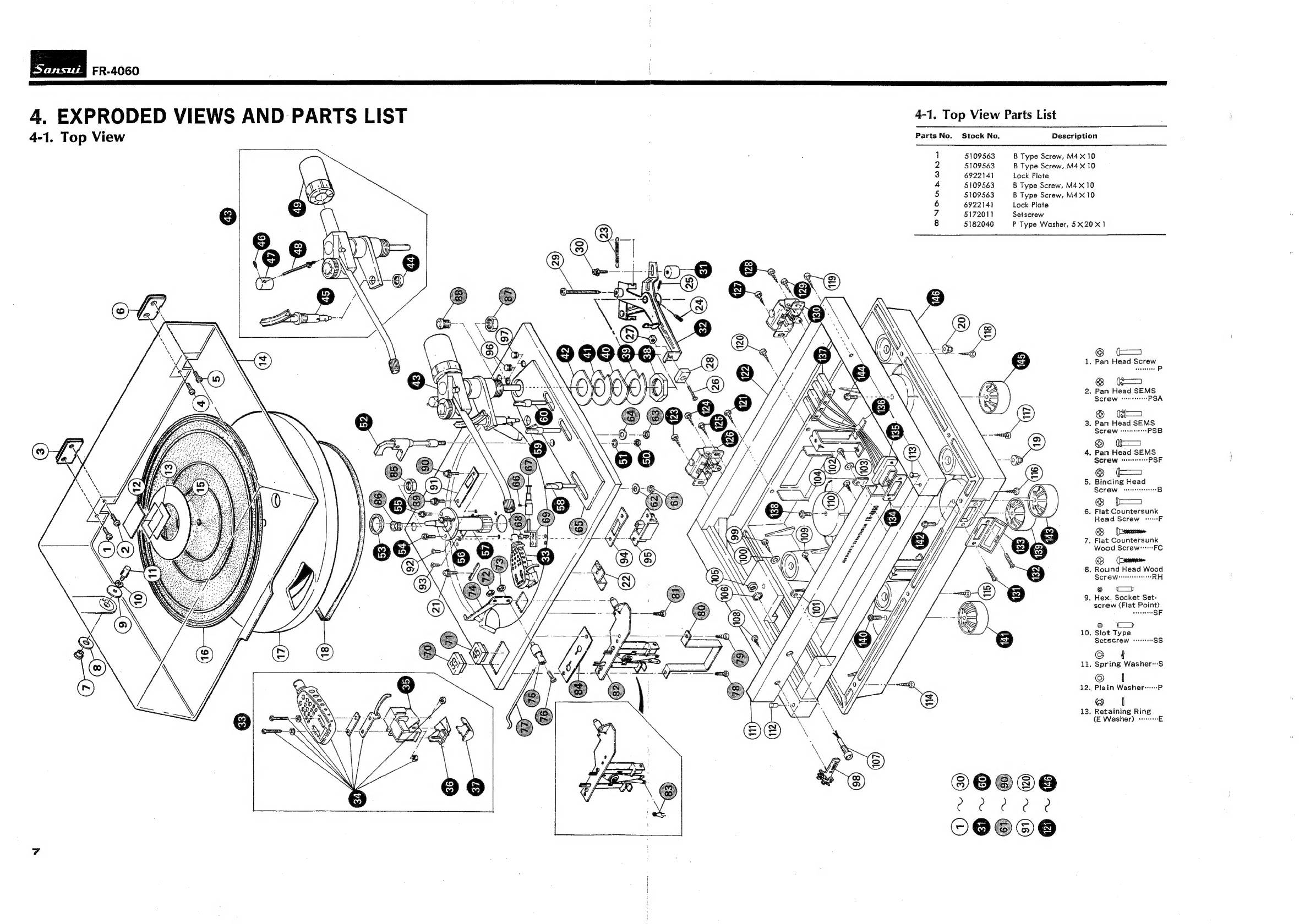
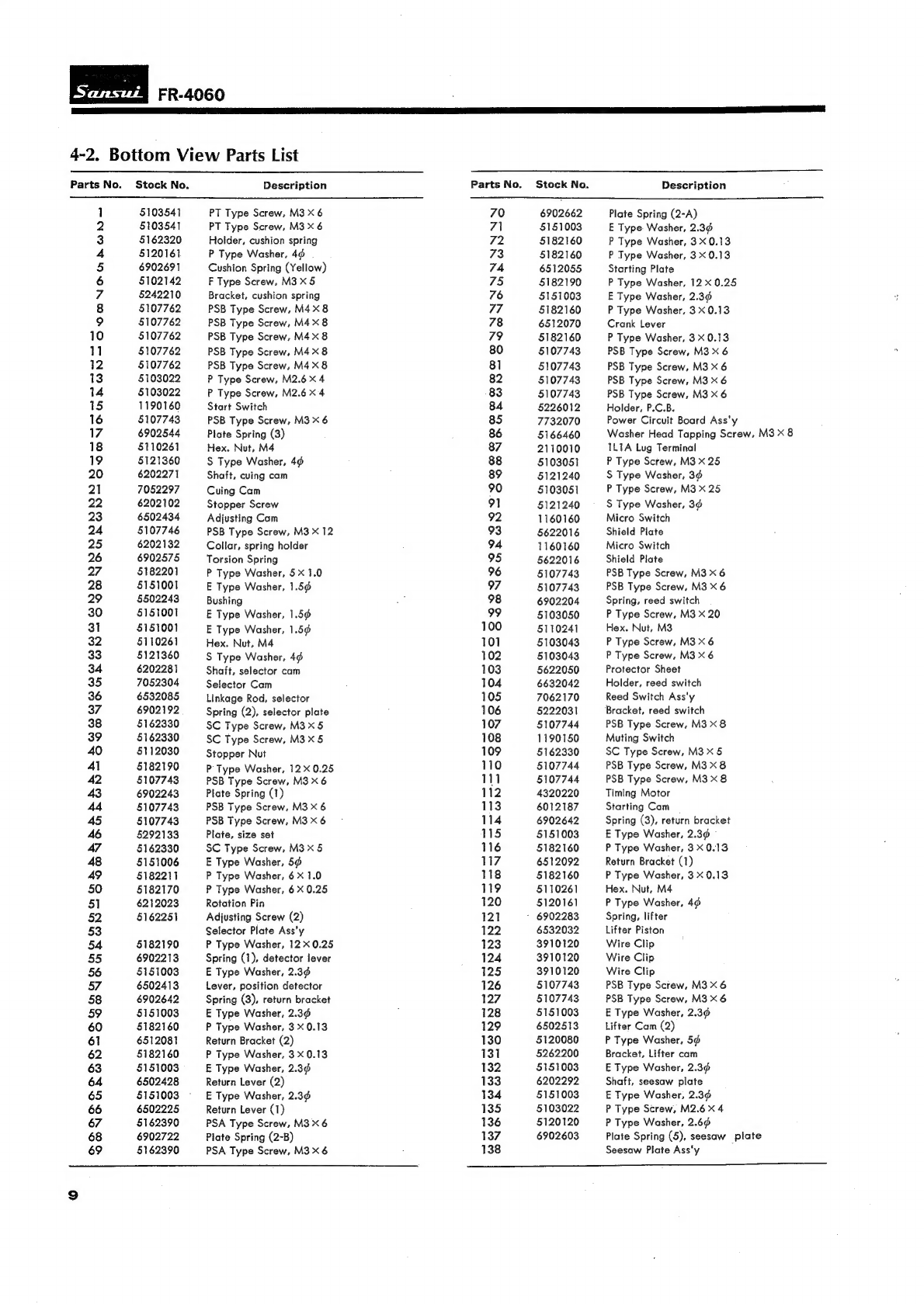
4.
EXPRODED
VIEWS
AND
PARTS
LIST.................-.
Peer
7
AT.
TOp
VIEW
ooo
cece
cece
cece
teen
ene
e
nen
ee
7,8
4-2.
POttOT
VIEW
setedsccs
Hei
ede
ea
tant
ees
aaa
9,10
5.
TROBLESHOOTING
CHART
..................50.
5.
eee
eee
eee
11
6.
PACKING
LIST.................
Rags
caked
dine
Dee
Sertionecs
st
12
7.
ACCESSORY
PARTS
LIST
..............
00.
e
cece
eee
eee
eens
12
8.
MAINTENANCE
...................0
00
cee
cece
eee
eee
eee
ees
13
8-1.
Replacement
of
Cartridge
iatwosleotaaeade
tamil
trees
eae
13
8-2.
Replacement
of
Capstan
........
520s
eee
eee
eee
eee
eens
13
8-3.
CUDPICALION:
-aSacccecaceedine
en
Rigen
elated
tees
13
8-4.
Changing
the
Line
Voltage
......-.
56.
eee
ence
eee
ees
13