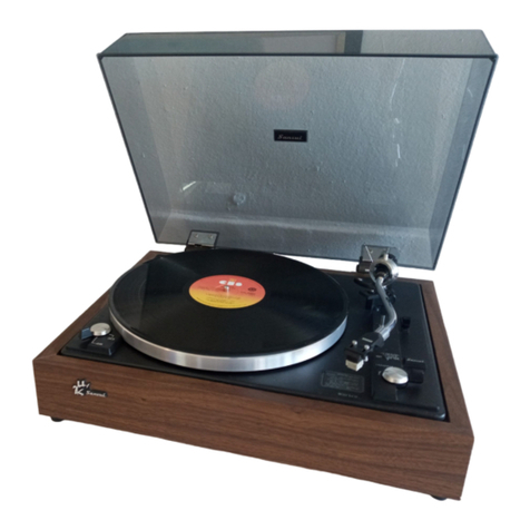
Sansui DA-P500 User manual

SERVICE
MANUAL
DA-T500
Hi-Fi
System
AUTOMATIC
DIRECT
DRIVE
TURNTABLE
SANSUI
DA-P500
(Silver
&
Black
Model)
-
SANSUI
ELECTRIC
Co.;
LTD.
©SPECIFICATIONS
DDO
iiccscaese
telepiinseiiiemmesiaas
Two-speed
direct-driven
SHECUS
scscccusemin
mecauanne
33-1/3,
45
rpm
PERE
ssevssisensecsceasccnes
nacinaassniseioe’
Aluminum
alloy
die-cast
304
mm
(12%)
diameter
4:
0]
ec
FG
Servo
DC
Motor
Wow
and
flutter.........
0.038%
(W.R.M.S.)
SIN
sigescncawiseemenxnnnm
Better
than
60
dB
(IEC-B)
|
ee
Better
than
72
dB
(DIN-B)
Tonearm
Tonearm
length
..........
220
mm
(8-11/16")
OVER
ANE:
crnenesuravaneinnns
17.5
mm
(3/4”)
Applicable
cartridge
weight
Lipaiieasinaitecsidelbneaaaiteaas
4
to
9g
Cartridge:
Model
SC-80
Output
voltage................
2.5
mV
per
channel
(1,000
Hz,
50
mm/sec)
Load
impedance..............
47
kQ
Tracking
force................
2.58
Dimensions
...............0..5.
430
mm
(16-29/32”)
W
120
mm
(4-23/32")
H
360
mm
(14-3/167)
D
Weight
......0.......0.......
3.8
kg
(8.4
Ibs)
net
4.6
kp
(10.1
tbs)
packed
Power
conumption..........2.5W
(DC
15V)
*
Design
and
specifications
subject
to
changes
without
notice
for
improvements.

CAUTION
1.
Some
printed
circuit
boards
are
not
supplied
as
the
assembied.
To
separate
these
in
this
service
manual,
the
stock
No’s
are
not
in-
dicated
at
the
ends
of
the
board
names.
However,
the
individual
parts
on
the
circuit
boards
are
provided
by
orders.
2.
Since
some
of
capacitors
and
resistors
are
omitted
from
parts
lists
in
this
service
manual,
refer
to
the
Common
Parts
List
for
capacitors
&
resistors,
which
was
issued
on
February
1983.
3.
Abbreviations
in
this
service
manual
are
as
follows.
--
eAbbreviations
List
os
pa
payee
C.R.
:
Carbon
Resistor
EB,
:
Bi-Polar
Electrolytic
S.R.
:
Solid
Resistor
Capacitor
Ce.R.
:
Cement
Resistor
E.B.L.
:
Low
Leak
Bi-Polar
M.R.
:
Metal
Film
Resistor
Electrolytic
Capacitor
FR.
:
Fusing
Resistor
Ta.C.
:
Tantalum
Capacitor
N.ILR.
:
Non-Inflammable
Resistor
Ec.
:
Film
Capacitor
A.R.
:
Array
Resistor
M.P.
:
Metalized
Paper
Capacitor
C.C.
:
Ceramic
Capacitor
PC.
:
Polystyrene
Capacitor
Os
:
Ceramic
Capacitor,
G.C.
—:
Gimmic
Capacitor
Temoerature
Compensation
A.C.
:
Array
Capacitor
EG
:
Electrolytic
Capacitor
V.R.
:
Variable
Resistor
E:L.
:
Low
Leak
Electrolytic
S.V.R.
:
Semi
Variable
Resistor
Capacitor
SW.
:
Switch

1.
PARTS
LOCATION
&
PARTS
LIST
1-1.
S-0121
Motor
Control
Circuit
Board
Component
Side
Parts
List
_
Parts
No.
Stock
No.
Transistor
eQ1
46359701
eQ2
46359701
eQ3
46359701
eQ4
46359701
eQ5
46359801
eQ6
46359801
eQ7
46359801
eQ8
46359801
eQ9
46367401
or
46367001
or
46367201
eQ10
46367401
or
46367001
or
46367201
eQ11
46367401
or
46367001
or
46367201
eQ12
46367401
or
46367001
or
46367201
Description
2SA952
2SA952
2SA952
2SA952
25C2001
2SC2001
2SC2001
2SC2001
2SA733A
2SA1115
2SA1048
25A733A
2SA1115
2SA1048
2SA733A
2SA1115
25A1048
2SA733A
2SA1115
2S5SA1048
Parts
List
Parts
No.
eZener
Diode
eDZ1
eR41
ec]
eC2
eVR1
eVR2
eVR3
Stock
No
:
Description
46113900
46639000
08451100
08451100
46366600
07241700
07241000
OoZt2-¥
240kQ
1/4W
MLR.
22uF
16V
E.B.
22uF
16V
E.B.
100kQ
(B)
S.V_R.,
speed
adj.
33-1/3
rpm
200kQ
(B)
S.V.R.,
speed
adj.
45
rpm
TKOMB}
S.V-R.,
wow
&
flutter
adj.
1-2.
S-0189
Speed
SW.
Circuit
Board
Com
ponent
Side’
0189
GCMK-35EHB
Parts
List
Parts
No.
Stock
No.
Description
e€Q13
46367401
2SA733A
or
46367001
2SA1115
or
46367201
2SA1048
e014
46367501
2SC945A
or
46367101
2SC2603
or
46367301
2S5C2458
eQ15
46367501
2SC945A
or
46367101
2SC2603
or
46367301
2SC2458
eQ16
46614001
2SA1283
eQ17
46367402
2SA733A
or
46367001
2SA1115
or
46367201
2SA1048
elC
elC1
46354301
H-300BC
or
46354302
H-300BC
elC2
46354301
H-300BC
or
46354302
H-300BC
elC3
46354400
BA6301
Parts
List
Parts
No.
Stock
No.
Description
gSW1
46368500
Push
SW.,
SPEED

2.
OTHER
PARTS
2-1.
Front
View
AOS
OWE
94
SSIS
Mee
Scopes
SLE
2-2.
Top
View
(Auto
Return
Adjustment
Screw)

Bottom
View
eVR1(33rpm)
eVR2(45rpm)
Parts
List
<Front
View/Top
View>
Parts
No.
Stock
No.
Description
1
13012300
45
r.p.m
Adaptor
2
00489400
E
Ring
56m
main
gear
3
13017200
Main
Gear
3-1
—
Lower
Trip
3-2
—
Upper
Trip
3-3
51822900
CS
Type
Washer,
3¢
4
13136400
Reject
Arm
5
13143400
Tension
Spring,
reject
arm
6
46368500
Push
SW.,
SPEED
7
47393200
Push
Knob,
SPEED
8
13234800
Indicator
Case
Cover
9
13235000
Indicator
Plate
10
13164300
Indicator
Holder
Ta
137142100
Push
Knob,
CUT
(Silver
Model)
13142200
Push
Knob,
CUT
(Black
Model)
12
13176300
Tone
Arm
Ass‘y
13
13176700
Main
Weight
Ass’y
14
13013500
Lifter
Knob
15
13138300
Lifter
Lever
Ass’y
16
13138700
Arm
Rest
17
13138500
Fook,
arm
rest
13
13167700
Binding
Head
Tapping
Screw,
M2x5
19
13138200
Lifter
Plate
20
13035600
Spring,
5.3¢
x
10
mm
(C)
21
13035700
Spring,
9.36
x
14
mm
(E)
22
00466500
P
Type
Washer
3¢
x
10
23
13011600
Elevation
Chip
24
13038010
Binding
Head
Tapping
Screw
M3
x
16
25
50624800
Cap
for
auto
return
adjustment
26
13140800
Turntable
Sheet
a
13147210
Turntable
Platter
28
13176600
Head
Sheel
Ass’y
29
13198200
Cartridge,
SC-80
30
13198100
Stylus,
SN-80
31
61921500
Screw
Assy
Parts
List
<
Bottom
View>
I
(DC
15V)
Parts
No.
Stock
No.
Description
1
11602500
Micro
Switch
2
13143710
Screw,
micro
switch
3
13038010
Pan
Head
Tapping
Screw
M3
x
16
(Adjusting
Screw)
4
69034400
Spring,
PU
Plate
5
13143000
Push
Pin
6
13038210
Screw,
Slide
arm
7
00467100
P
Type
Washer
5¢
x
10x
1.0
8
13051900
Steel
Ball
5@
9
13136700
Reject
Lever
(3)
10
13038300
Reject
Lever
(1)
ee
07254700
Strain
Relief
12
13234400
PU
Output
Cord
13
13234300
DC
Power
Cord
14
18028700
SSD703A
DD
Motor
Ass’y
with
control
circuit
board
(S-0121)
ae)
08320700
Brazier
Head
Tapping
Screw
M4x
12
13153500
Insulator

3.
BLOCK
DIAGRAM
45rpm---6.3V
33rpm---5.6V
ree
33/45
FG
7
9
out
2
;
(S-Ol2!)
|
me
eQia
eQis
Parttern
drawing
motor
section
($0121
Motor
Control
Circuit
Board)
Pattern
a?
:
<BA-6301>
16
«15
'
{
Motor
is
{i
Motor
Oriving
Coil!
\
:
'
Drivig
Coil
‘
/
,
\
+
Driving
Cot
\
\!
ui
Driving
Coil
L3
ST
a
~~
a
4.
ADJUSTMENTS
<For
this
Adjustments,
combined
model
DA-T500
or
regulated
DC
power
supply
is
required.
>
4-5.
Speed
Adjustment
e
Preseting
If
DA-T500
is
used,
connect
DC
power
cord
of
the
unit
to
DC
OUT
See
Bottom
View
on
page
4.
jack
of
DA-T500.
If
regulated
DC
power
supply
is
used,
connect
it
to
the
unit
as
Bot-
Strobo
marking
pattern
tom
view
on
page
4.
4-1.
Adjustment
of
the
Auto
Return
KVRI
1)
The
adjusting
screw
in
top
view
is
one
to
adjust
the
position
of
Auto
(S-0121)
appears
to
stand
still,
kVR2
Same
as
above
.
Return
when
stylus
reaches
lead-out
groove.
2)
Make
adjustment
of
the
screw
in
such
a
way
that
stylus
lifts
up
au-
tomatically
around
the
middle
way
of
lead-out
groove.
(S-0121)
eee
i
asa
;
——
Namely
turn
the
adjusting
screw
clockwise
is
for
leading
and
coun
Note:
Set
kVR3
(S-0121)
center
position.
terclockwise
if
for
lagging.
After
adjusting
the
screw
properly,
check
its
operation
a
few
times.
3)
4-2.
Adjustment
of
the
Clearance
between
PU
plate
and
Micro
Switch
After
replacing
the
micro
switch,
adjust
the
clearance
between
PU
plate
and
micro
switch
(See
Fig.
4-1)
to
be
approximately
0.3
mm
at
the
tonearm
on
the
arm
rest
by
the
clearance
adjusting
cam.
Fig.
4-1
PU
Plate
4-3.
Adjustment
of
the
main
gear
When
the
main
gear
makes
abnormal
mechanical
noise
caused
by
Recs
touching
to
the
pinion
gear
during
playing
record
disc,
adjust
its
posi-
\
tion
with
cam
2
to
make
even
clearance
between
the
circuilar
arc
por-
of
tion
of
the
main
gear
and
the
pinion
gear.
|
\
prsseeeeuact
\
Pa
4-4.
Adjustment
of
cartridge
mounting
position
;
Ne
es
Fig.
4-2
ede
these
fy
Center
Pinion
Gear",
aD
i
choft
“ae
(DD
Motor)
Adjust
the
cartridge
mounting
position
as
shown
in
Fig.
4-2.
K-11
mm

5.
SCHEMATIC
DIAGRAM
eR34
20k
(45r.p.m,
67.
SH2)}
EG
ae
S
le
330,
—
-3
687
Ii
eic3
BA63OI
oa
9
10
ile
14
eR35
27k
eR3B8
47k
13
*Design
and
specifications
subject
to
change
without
notice
for
improvement.
*La
presention
et
les
spécifications
sont
susceptibles
d'étre
modifiées
sans
préavis
par
suites
d’améliorations
éventuelles.
*Anderungen,
die
dem
technischen
Fortschritt
dienen,
bleiben
vorbehalten.
eVR2
200k
eR4!
240k
eR30
470k
ee
eVR!
100k(8)
R28
12k
eR27
680
eR29
56k
SS
eeeeeeeeseseses
eR43
10k
a
eR20
|.
2k
eQl~
4
eSA952
M,L
RESISTORS
eQ5~
8
2sC200!
M,L
Are
in
ohms,
1/4
Wotts
+
5%
Tolerance
eQg~l2
2SA733A
Q,P
Unless
Otherwise
Noted.
k:kQ,
M:
MQ
2SAINS
£,F
CAPACITORS
2SAIO048
Y,GR
Are
in
pF,
Unless
Otherwise
Noted.
P:pF
eQI3
2SA733A
P
2SAINS
F
SYMBOL
2SAIO048
GR
A
Ceromic
eQ!4
15
2SC945A
P
AT
Ceramic
(Temperature
Compensation)
2SC2603
F
OF
Ceramic
(Feed
Through)
2SC2458
GR
-)
Low-Leok
Electrolytic
eQl6
2SAI283
E
(B.P)
Bi-
Polor
Electrolytic
eQi7
2SA733A
P
O(B,P)
Low-Leok
Bi-Polar
Electrolytic
2SAIIIS
F
(To)
Tantalum
Electrolytic
2SAI048
GR
©
Film
@(m)
Mylor
@i(p.c)
Polycorbonate
©(p.p)
Polypropylene
©
Metalized
Poper
@
Polystyrene
A
Gimmic
Mic
Mica
0.C
Oil
Each
D.C.
Voltage
meosured
by
the
instruments
discribed
below
shows
the
nominal
vatue
in
volts
at
33!/3r.p.m
Measuring
instruments
Volt
Meter
DC
20k2/V,
AC
IkQ/V
|
Osciloscope
SMHz
|
2SA733
2SA952
2SA1015
25A
1048
-2SA1115
25A1283
25C2001
28C2458
25C945A
Micro
SW.
DC
Power
Cord
3

6.
PACKING
LIST
UL
LS
ae
en
dee
nee
ra
eer
Parts
No.
©
Stock
No.
7.
ACCESSORY
LIST
Description
Stock
No
Description
|
_
Protector
Board
13142600.
Auto
Hinge,
dust
cover
Ass’y
Z
13142400
Dust
Cover
Ass’y
7
13176700
Main
Weight
Ass‘y
S38
-—
Polyethylene
Bag,
dust
cover.
aarti
ea
Sele
a
ieee
a
3
Ass’y
|
eNote:
There
are
two
types
of
unit
in
DA-P500.
—
|
“A
13140800
Turntable
Sheet
| |
1)
The
unit
with
a
Dust
Cover
Ass’y.
5
13147210
Turntable
Platter
2)
The
unit
without
a
Dust
Cover
Ass'y.
6
91166000
Polyethylene
Bag,
turntable
Platter
(“M"
mark
is
indicated
on
the
Carton
Case.)
7
13170400
Styrofoam
Packing,
front
| | |
8
13170500
—-
Styrofoam
Packing,
rear
g
_
Accessories
Cover
10
91122710
Polyethylene
bag,
turntable
unit
11
13234100
Carton
Case
(DA-P500)
<Silver
Model
>
13234200
Carton
Case
(DA-P500)
<
Black
Sate.
Model>
_
13236200
.
Carton
Case
(DA-P500
M
)
| |
<
Silver
Model
>
13236300
Carton
Case
(DA-P500
M
)
<Black
Model
>
14-1,
Izumi
2-chome,
Suginami-ku,
Tokyo
168
Japan
PHONE:
(03)
324-8891/TELEX:
232-2076
(international
Division)
1250
Valley
Brook
Ave.
Lyndhurst,
N.J.
07071
U.S.A.
|
17150
South
Margay
Ave.
Carson,
California
90746
U.S.A.
_
SANSUI
ELECTRONICS
CORPORATION:
_
3306
Koapaka
5t.
Honolulu,
Hawaii
96819
U.S.A.
LE
D.:
Unit
10A,
Lyon
Industrial
Estate,
Rockware
Avenue,
Geenford,
Middx
UB6,
OAA,
England
Pau
Ehrich
Strasse
8,
6074
Rodermark
2,
West
Germany
.
(SM1-115)
0
Printed
in
Japan
<Stock
No.
36484700>_
SANSUI
ELECTRONICS
(U.K.)
SANSUI
ELECTRONICS
G.M.B.H
Table of contents
Other Sansui Turntable manuals

Sansui
Sansui P-M7 User manual

Sansui
Sansui FR-4060 User manual

Sansui
Sansui SR-212 User manual

Sansui
Sansui SR-222MKV User manual

Sansui
Sansui SR-222 User manual
Sansui
Sansui XR-Q9 User manual

Sansui
Sansui SR-9219 User manual

Sansui
Sansui SC-3300 User manual

Sansui
Sansui FR-D25 User manual
Sansui
Sansui SR-636 User manual