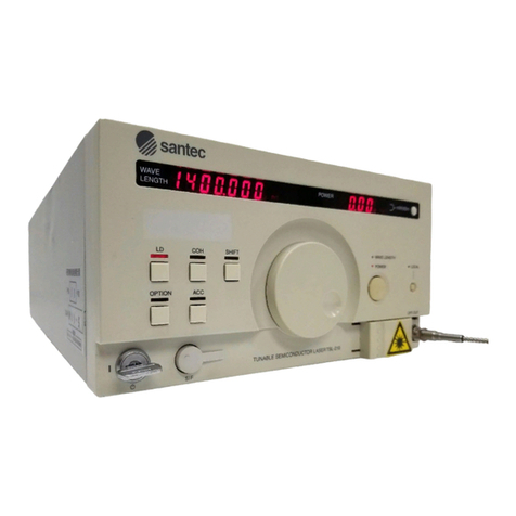
Santec ECL-210 User manual

Artisan Technology Group is your source for quality
new and certied-used/pre-owned equipment
• FAST SHIPPING AND
DELIVERY
• TENS OF THOUSANDS OF
IN-STOCK ITEMS
• EQUIPMENT DEMOS
• HUNDREDS OF
MANUFACTURERS
SUPPORTED
• LEASING/MONTHLY
RENTALS
• ITAR CERTIFIED
SECURE ASSET SOLUTIONS
SERVICE CENTER REPAIRS
Experienced engineers and technicians on staff
at our full-service, in-house repair center
WE BUY USED EQUIPMENT
Sell your excess, underutilized, and idle used equipment
We also offer credit for buy-backs and trade-ins
www.artisantg.com/WeBuyEquipment
REMOTE INSPECTION
Remotely inspect equipment before purchasing with
our interactive website at www.instraview.com
LOOKING FOR MORE INFORMATION?
Visit us on the web at www.artisantg.com for more
information on price quotations, drivers, technical
specications, manuals, and documentation
Contact us: (888) 88-SOURCE | sales@artisantg.com | www.artisantg.com
SM
View
Instra

EXTERNAL CAVITY
TUNABLE LD LIGHT SOURCE
Operation Manual
ECL-210
Artisan Technology Group - Quality Instrumentation ... Guaranteed | (888) 88-SOURCE | www.artisantg.com

ECL-210 Operation Manual
Disclaimer
Every effort has been made to ensure the information contained in this manual is accurate and easily
understandable. Santec shall not, however, be liable for errors contained herein, or for incidental or
consequential damages in connection with the use of this material.
Copyright 2000, Santec Corporation, Japan. No part of this document may be reproduced, stored in a
retrieval system, or transmitted in any form or by any means, electronic, mechanical, photocopying,
recording, or otherwise without the prior written permission of Santec Corporation, Japan.
Artisan Technology Group - Quality Instrumentation ... Guaranteed | (888) 88-SOURCE | www.artisantg.com

EXTERNAL CAVITY TUNABLE LD LIGHT SOURCE ECL-210
This manual explains the operation and safety features of the ECL-210 External Cavity Tunable LD
Light Source. To ensure the safe operation of the instrument, and to prevent the risk of personal injury
and/or damage to the equipment we recommend that you read the manual fully before commencing
installation and operation. In particular Chapter 6 outlines the precautions necessary to ensure safe
operation. The following safety symbols are used throughout the manual and on the equipment to
indicate safety related information.
DANGER!!
CAUTION
Packing Materials
The original packing materials are required to ensure the safe long term storage and safe transportation
of this equipment. It is recommended that all packing materials are kept for these purposes.
This indicates a dangerous procedure that could result in serious injury or
death if not performed properly.
This indicates there is a danger due to laser radiation. Do not look directly at
the laser beam or look at the beam by eye through any optical instrument.
About This Manual
This indicates a hazardous procedure or danger that might result in injury or
that could damage the equipment if proper precautions are not taken.
This mark is used on the equipment as a warning of danger.
Artisan Technology Group - Quality Instrumentation ... Guaranteed | (888) 88-SOURCE | www.artisantg.com

ECL-210 Operation Manual
About this Manual
1. Introduction
2. Specifications
2.1. ECL-210 Standard Specification
2.2. MLS-2100 Standard Specification
2.3. MLS-8100 Standard Specification
3. Features
3.1. Tuning Wavelength
3.2. Coherence Control
3.3. LD Injection Current, Control of Circumstance Temperature
3.4. Precise Optical Power Control
3.5. Built-in Attenuator
3.6. Fine Wavelength Tuning Control
3.7. Plug & Play
3.8. Communication Interfaces
4. Principle of Operation
4.1. ECL Principle of Operation
4.2. The Unit Principle of Operation
5. Panel Descriptions
5.1. Front Panel
5.2. Rear Panel
5.3. Bottom Panel
5.4. Side Panel
6. Safety Information
6.1. Mains Voltage
6.2. Installation
6.3. Safe Operation
Table of Contents
Artisan Technology Group - Quality Instrumentation ... Guaranteed | (888) 88-SOURCE | www.artisantg.com

EXTERNAL CAVITY TUNABLE LD LIGHT SOURCE ECL-210
7. Operation Procedures
7.1. Contents of Fundamental Operation
7.2. Turning Power On
7.3. Optical Fiber Connection
7.4. Selecting Units in MLS
7.5. MLS MODE
7.6. MLS Matrix LED
7.7. Shuttle Switch
7.8. Driving LD and Shutting LD Off
7.9. Setting Wavelength
7.10. Setting Optical Output Power
7.11. ACC Function
7.12. Fine Tuning Function
7.13. Coherence Control
7.14. Low Frequency Modulation
7.15. Setting GPIB Address and Delimiters
7.16. Parameter Memory of Each Unit
7.17. Plug and Play
7.18. Shutting Power Off
8. Communication Interfaces
8.1. GPIB Control
8.2. RS-232C Control
8.3. Control Commands
9. Example Programs
8.4. GPIB Program
8.5. RS-232C Program
Artisan Technology Group - Quality Instrumentation ... Guaranteed | (888) 88-SOURCE | www.artisantg.com

ECL-210 Operation Manual
10. Care and Maintenance
10.1. Care
10.2. Maintenance
10.3. Cleaning the Optical Connectors
10.4. Changing the Fuse
11. Option
12. Troubleshooting
13. Warranty
Artisan Technology Group - Quality Instrumentation ... Guaranteed | (888) 88-SOURCE | www.artisantg.com

EXTERNAL CAVITY TUNABLE LD LIGHT SOURCE ECL-210
1-1
1Introduction
The ECL-210 is an electronically tunable multi-channel LD light source. It utilizes Santec's
considerable expertise in external cavity type tunable semiconductor laser design, and in particular
uses an interference filter in the external cavity for wavelength control and selectivity.
Wavelength and optical power can be set up by simple operation compared with usual manual tuning
method. With the growth of the telecommunications industry, there is a need for tunable light sources
to evaluate EDFA, and DWDM. Santec designed the ECL-210 to meet this need with a unit that has
precise wavelength tuning accuracy, excellent wavelength and power stability, and high optical output
power. Used as a stand-alone unit or as part of a larger test system, the ECL-210 is the excellent choice
as a tunable light source to use in optical research and development, inspection, production testing.
The ECL-210 is wavelength stable light source which utilizes both a wavelength selecing and a
wavelength locking filter filter inside the unit. High precision temperature control of wavelength
locking filter enables extremely high wavelength stability and repeatability to be achieved.
To operate the ECL-210 the unit needs to be installed in either the MLS-2100 or MLS-8100 Rack.
These racks provide a power supply and the control electronics for operation. The MLS-2100 is a two
channel rack and the MLS-8100 allows up to eight channels to be used simultaneously.
Artisan Technology Group - Quality Instrumentation ... Guaranteed | (888) 88-SOURCE | www.artisantg.com

1-2
ECL-210 Operation Manual
Artisan Technology Group - Quality Instrumentation ... Guaranteed | (888) 88-SOURCE | www.artisantg.com

EXTERNAL CAVITY TUNABLE LD LIGHT SOURCE ECL-210
2-1
Specications
2
2-1 ECL-210 standard specication
Specication
parameter Unit Min. Spec. Max. Note
Wavelength
Tuning range nm 1530 - 1610
Minimum tuning nm 80 - -
Resolution nm - - 0.024 <0.001nm When using ne tuning
Accuracy nm - - 0.1
Repeatability nm - - 0.01 Number of times of measurement n=50, Measured at center
wavelength
Stability nm - - 0.01 1 hour, Measured at center wavelength
Fine tuning range GHz 200 - - 1.6nm(Typ.)
Power
Maximum output power mW
8 - -
6 - - Minimum output power between a certain 40nm
4 - - Minimum output power
Accuracy % - - 5
Repeatability dB - - 0.01 Number of times of measurement n=50, Measured at center
wavelength, +6dBm
Stability dB - - 0.01 1 hour, Measured at center wavelength, +6dBm
Flatness dB - - 0.2 Measured at +6dBm
Buit in attenuator dB 0 - 20 Resolution: 0.04dB (Typ.)
Environmental condition
Operating temp. range oC 20 - 30
Operating humidity
range % - - 80 No condensation
Storage temp. range oC 10 - 40
Storage humidity range % - - 80 No condensation
Recalibration period Year 1 - - Recommended
Spectrum
Spectrum line width MHz - - 0.2 Coherence control OFF
0.2 - 200 Coherence control ON
SSR dB 50 - - 50dB(Typ.)
Interface
Optical connector - - FC -
Optical ber - - SMF - SM, 10/125-UV/UV-250
Connector polish - - SPC - Supoer polish connector
RS-232IF - - Yes -
LF Modulation
Modulation range KHz 0 - 10 Measured at -3dBm
Input level V -1 - 1
Modulation coefcient mA/V - 100 -
Input impedance KW - 4.7 -
Modulation input - - SMA - Input from the rear panel
Power supply
Laser safety class - 3A
Dimensions
Width, Height, Depth mm 35,85,350 Excludes the projection
Weight kg 0.5
Artisan Technology Group - Quality Instrumentation ... Guaranteed | (888) 88-SOURCE | www.artisantg.com

2-2
ECL-210 OPERATION MANUAL
NOTE
Optiona List
The warranty for ECL-210 is one year. We recommend to have ECL-210 inspected and
calibrated regularly ( once a year recommended).
parameter Unit Min. Spec. Max. Note
Wavelength
Tuning range nm 1290 - 1360 Maximum tuning range: >70nm
1430 - 1460 Maximum tuning range: >80nm (choose from 1430~1640nm)
Power
Maximum output power mW 10 - - High power output
Interface
Optical connector - - SC -
Optical ber - - PMF - SLOW axis, Polarization extinction ratio>17dB,Polarization angle
error<10o
Connector polish - - APC - Angled polish connector*1
RF Modulation
Modulation range MHz 1 - 100 Measured at -3dB
input level dBm - - +0
Input impedance W - 50 -
Modulation input - - SMA - Input from the front panel
*1: Face of ferrule: SS-CS-001A FH(Protrusion): -100~100nm / ROC(Spherical radius): 5~12nm / AA(Polish angle): 7.7~8.3º /
AO(Elleptical center): ≤50µm / Key error: -0.5~0.5º
Artisan Technology Group - Quality Instrumentation ... Guaranteed | (888) 88-SOURCE | www.artisantg.com

EXTERNAL CAVITY TUNABLE LD LIGHT SOURCE ECL-210
2-3
Options
Black cover panel
Ear for standard rack mount
CP-10E (Control Key Pad)
Options
Black cover panel
Ear for standard rack mount
CP-10E (Control Key Pad)
2-2 MLS-2100 standard specication
2-3 MLS-8100 standard specication
Item Unit Min. Standard Max. Remarks
Slot - - - 2 -
I / F - - - - GP-IB
Voltage V 90 - 250 Switch type
Frequency Hz 48 - 62 -
Max. Power W - - 50 2 Units
Dimentions mm - 230X412X88 - WXDXH
Weight kg - 6 - Without Units
Item Unit Min. Standard Max. Remarks
Slot - - - 8 -
I / F - - - - GP-IB
Voltage V 90 - 250 Switch type
Frequency Hz 48 - 62 -
Max. Power W - - 400 8 Units
Dimentions mm - 442X412X88 - WXDXH
Weight kg - 8 - Without Units
Artisan Technology Group - Quality Instrumentation ... Guaranteed | (888) 88-SOURCE | www.artisantg.com

2-4
ECL-210 OPERATION MANUAL
Artisan Technology Group - Quality Instrumentation ... Guaranteed | (888) 88-SOURCE | www.artisantg.com

EXTERNAL CAVITY TUNABLE LD LIGHT SOURCE ECL-210
3-1
Features
3
3-1 Tuning Wavelength
The oscillation wavelength can be widely tuned by controlling the loss against the components
in selecting wavelength inside of external cavity module. The way of ECL selecting wave-
length is to make the two independent OBPF and FLF work together. The excellent selectivity
of FLF enables the wavelength of LASER to be locked automatically. This high-precise FLF
control achieves superior wavelength accuracy, stability, and repeatability. OBPF and FLF
are controlled by the control circuit in ECL, and those can be easily operated by setting target
wavelength from external through MLS. For a small amount of wavelength rectication after
setting wavelength, it is possible to set ne tuning independently.
3-2 Coherence Control
The oscillated spectrum linewidth of the ECL-210 is fairly narrow in comparison with normal
semiconductor lasers. Spectrum linewidth is one of the factors that determines light coherence,
and the narrower the spectrum linewidth, the more improved the coherence. Considering the
length of ber used or the complexity of some test set-ups, there is the possibility that within
the length of ber in the test set-up there is a reection point in the optical ber transmission
system, optical output power changes within the ber due to interference. To combat this, the
ECL-210 is equipped with a Coherence Control.
Coherence control is radio frequency modulation against the external cavity module, and the
spectrum line width of the narrow sense isn't expanded. However, it effects very much for the
oppression of Brillouin scattering occurred with high optical power and optical power vacilla-
tion by interference in ber. ECL is equipped with coherence control function for structuring a
stable system on a few residual reection points and high optical power. The coherent control
enables to control ON/OFF and adjust the level.
0.3dB (p-p)
326.0
306.0
286.0
326.0
306.0
286.0
100sec.
600sec.
without
Coherence
Control
85kHz
FREQUENCY [Hz]
Artisan Technology Group - Quality Instrumentation ... Guaranteed | (888) 88-SOURCE | www.artisantg.com

3-2
ECL-210 OPERATION MANUAL
3-3 LD injection Current, Control of Circumstance Temperature
0.03dB (p-p)
326.0
306.0
286.0
326.0
306.0
286.0
100sec.
600sec.
with
Coherence
Control
46.5MHz
FREQUENCY [Hz]
The measurement example of optical power stability and spectrum line width are shown below.
Those are when connecting optical ber type 3dB coupler to ECL output terminal. The open
terminal of optical ber is a connector with SPC and the rate of reection here is approximately
4%.
To keep a stable oscillating condition of the semiconductor laser, the ECL precisely controls
injection current and adjusts for ambient temperature change.
3-3-1. Control of LD Injection Current
The drive circuit with LD protection drives the injection current, and APC circuit etc. by digi-
tal PI control adopting optical power monitor signals against the circuit. When it reaches to a
hardware limit, the current is clipped and the status LED of MLS is lit. Also, it is possible to
control the current for the drive circuit by voltage signals from external. (Refer to 9-13. Low
Frequency Modulation)
3-3-2. Control of Circumstance Temperature
The high precise digital PI control of LD block enables stable temperature. When the tempera-
ture control is unstable too, the MLS status LED is lit. The detail information of each unit can
be recognized with communication commands.
The protection circuit is also equipped with this system and each unit against abnormal
voltage input.
NOTE
Artisan Technology Group - Quality Instrumentation ... Guaranteed | (888) 88-SOURCE | www.artisantg.com

EXTERNAL CAVITY TUNABLE LD LIGHT SOURCE ECL-210
3-3
13-4 Precise Optical Power Control
ECL has two modes to control optical power: Automatic Power Control (APC) mode, and
Automatic Current Control mode.
3-4-1. High precise Optical Power Monitor
ECL has machinery monitoring divergently a part of light, to monitor optical output, using
optical ber coupler of low loss and wavelength independent type. ECL does wavelength sensi-
tivity compensation, linear compensation of optical detector, cascade gain amplier control.
3-4-2. APC Mode
In APC mode, ECL feedbacks this high precise optical power monitor signals, and controls
optical power automatically by digital PI control. When APC mode is active and wavelength
is reset, almost same optical power can be seen. Note that in a oscillation wavelength, the set
optical power may not be able to achieve, even if the injection current is driven to the current
limit.
Water molecule absorbs light in 1300nm~1500nm and the output power decreases
when measuring with optical spectrum analyzer. It is impossible to avoid it because it
is a physical phenomemon. We recommend to use ECL-210 in the condition with the
extremely low humidity or avoid the water absorption points.
APC mode Current limit
APC working range
Optical output power
Wavelength
NOTE
Artisan Technology Group - Quality Instrumentation ... Guaranteed | (888) 88-SOURCE | www.artisantg.com

3-4
ECL-210 OPERATION MANUAL
3-4-3. ACC Mode
In ACC mode, ECL controls with set current in advance. It is possible to stabilize optical
power by adding the feedback signals from external optical power criteria into low frequency
modulation terminal. Note that optical power may uctuate extremely depending on external
modulation signal input.
I=Const.
ACC mode
Optical output power
Wavelength
3-5 Built-in Attenuator
3-5-1. Introduction
By adopting an external cavity structure the product has maintained various semiconductor
laser features. In particular this structure makes it possible to tune the wavelength of the laser
light. However, the optical output power is controlled by tuning the LD injection current.
This causes a change in the optical path length in the LD that can consequently cause an opti-
cal wavelength shift or cause difculty in maintaining adequate SSR (side-mode suppression
ratio). To counter these problems, a tunable attenuator (ATT) is tted on the output side of the
external cavity. The data below shows a comparison of the spectrum of the output signal with
the output power set to -15dB with and without the attenuator.
Without ATT With ATT
Artisan Technology Group - Quality Instrumentation ... Guaranteed | (888) 88-SOURCE | www.artisantg.com

EXTERNAL CAVITY TUNABLE LD LIGHT SOURCE ECL-210
3-5
NOTE
Output power is controled by controling current to LD. When output power setting
exceeds ATT control range in APC mode or ACC controls current by communication
command in ACC mode, S/N characteristics decrease as the current decreases.
3-5-2. Features and Principle Structure
The feature is the ability to reduce the optical output power loss from installing a variable
attenuator in the optical test set-up. By including an internal ATT, variable attenuation is real-
ized with a minimum of optical power loss when compared with an external attenuator set-up.
An attenuator is made of a mechanically tunable graded ND lter. It can be tuned continuously
with the resolution of 0.1dB within 0 to 20dB attenuation range.
3-5-3. Control Method
ATT option is not designed to frequently control the attenuation level. Both manual control
and automatic control are available and these modes can be set using the external communica-
tion port.
1) Manual Control
Manual control of ATT is initially active when the unit is operated in ACC mode. It directly
controls attenuation by setting parameter from the MLS front panel or via the external commu-
nication.
2) Automatic Control
Automatic control of ATT is initially active when the unit is operated in APC mode. When
APC is in operation and the APC target value changes, if the current reaches its upper limit,
the lower attenuation level is selected. If for some reason the APC target value setting is not
achievable, the previous attenuation setting is used.
3-5-4 Control Method of Use
1) Manual Control Mode (ACC mode)
Manual control is possible using the external communication interface. Switch to manual con-
trol mode when the unit is operated in ACC mode or with external low frequency modulation.
ATT is set to 0dB if APC mode is switched to ACC mode while automatic control mode of
ATT is active. Manual control is effective only in ATT manual mode or in ACC mode.
2) Automatic control (APC mode)
Automatic control is available via key operation from the MLS front panel or via mode switch-
ing through the external communication port. In APC mode, ATT can be automatically set
depending on the change of optical output power. When it is in Automatic Control mode LED
of APC is lit and in the case of control by external communication 1 is added to the 4th digit of
the status display. Details of reading the status display are given in section 10.
3) Conrmation of set value (AT)
Set value of ATT changes by automatic control. And this value can be conrmed (read-out) via
external communication command (AT). Set value is xed in manual control mode.
Artisan Technology Group - Quality Instrumentation ... Guaranteed | (888) 88-SOURCE | www.artisantg.com

3-6
ECL-210 OPERATION MANUAL
ECL controls OBPF and FLF independently against wavelength input. When some compensa-
tion is required after wavelength stable, it is possible to control only FLF independently.
On the usual system, when units are required to be exchanged or to be added, the stable system
must be down, and be exchanged or added, then, the system must be start up. However, it is
possible to be plugged in and out with power on. In this case, re-start of the system is unneces-
sary only by the warm-up of the added unit. (Refer to 7.16. Plug and Play)
GP-IB, RS-232C* are equipped with this system. The structuring various systems is possible
by external communication control.
* RS-232C is an option.
3-6 Fine Wavelength Tuning Control
3-7 Plug & Play
3-8 Communication Interface
Artisan Technology Group - Quality Instrumentation ... Guaranteed | (888) 88-SOURCE | www.artisantg.com

EXTERNAL CAVITY TUNABLE LD LIGHT SOURCE ECL-210
4-1
4Principle of Operation
FIG.1. Structure diagram of ECL-210
4.1. ECL Principle of Operation
FIG.1 shows the structure of ECL-210.
To the semiconductor laser (LD), employed is a Fabry-Perot type LD whose one end surface is
coated by AR (anti reflection). In the LD block, an inside lens and output lens in an external
cavity to configure an external cavity and Frequency Lock Filter, and an isolator to prevent return
light from the outside are arranged in a temperature control is carried out by a peltier element in
a high precious manner.The light injected from AR coated surface of LD is collimated by the
external cavity inside lens, and its wavelength is selected by the optical band path filter (OBPF)
and frequency lock filter (FLF), and reflected by the external cavity mirror, and led from the AR
coated surface to LD by the external cavity inside lens once again. When current is supplied into
LD and the gain inside of LD becomes sufficient, laser oscillation is carried out by the external
cavity.
The laser light goes through tunable attenuator (ATT) (* 1) and bounded to the optical fiber. The
optical fiber is diagonally processed so as to prevent interference in fiber, and only connector for
output employs SPC. FC-APC connector, SC connector and polarization maintaining fiber out-
put are available as options.
The oscillation wavelength of ECL-210 is controlled by OBPF and FLF individually. The merit
of ECL-210 is these two independent components controlled.
ISO
L1 L2
Artisan Technology Group - Quality Instrumentation ... Guaranteed | (888) 88-SOURCE | www.artisantg.com
Table of contents
Other Santec Measuring Instrument manuals
Santec
Santec TSL-550 User manual

Santec
Santec PEM-320 User manual

Santec
Santec PLS-100 User manual

Santec
Santec TSL-710 User manual

Santec
Santec TSL Series User manual

Santec
Santec TSL-570 User manual

Santec
Santec MPM-210 User manual

Santec
Santec TSL-510 User manual

Santec
Santec OptoTest OP760 Series User manual

Santec
Santec PEM-340 User manual