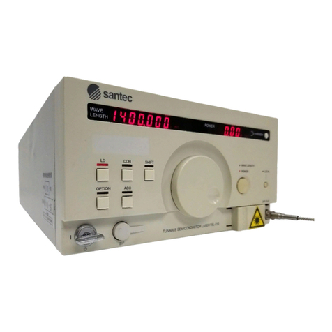
Santec TSL-710 User manual

Tunable Semiconductor Laser
Operation Manual
TSL-710

TSL-710 Operation Manual
Trademarks
Notes to Users
1) Copyright 2005, Santec Corporation. All rights reserved. No part of this Operation
Manual may be reproduced or transmitted in any form or by any means, electronic or
mechanical, for any purpose, without the prior written permission of Santec.
2) Information in this Operation Manual is subject to change without notice.
3) Information of this Operation Manual is prepared with careful examination, however,
in the event of any mistake, please contact us.
Notes in Bringing This Product Out of Japan
1) When this product is brought out of Japan, some laws or regulations of a destination
country may prohibit this product from being used there. In such countries, the use of
this product may lead to being punished, but the Company shall not be responsible for
such a case at all, which please note.
2) When this product is exported (or brought out of Japan), if this product is applicable
to a strategic material specied in “Foreign Exchange and Foreign Trade Control Law”,
then required is an export permit of the Japanese Government under the law.
is a trademark of Santec Corporation.
TSL-710 is a trademark of Santec Corporation.

Tunable Semiconductor Laser TSL-710
Introduction
Thank you very much for your having purchased our product, Tunable Semiconductor
Laser TSL Series. This Operation Manual contains information necessary for the
operation of TSL-710, and it is intended for those with sufcient knowledge enough to
of laser danger and its safe control. Before operating TSL-710, you should rst read
thoroughly through this Operation Manual and become familiar to its contents. After
reading this Operation Manual, keep it at your ngertip for easy reference at any time.
The packing materials and box of this product are needed for long-term storage or
transportation, therefore, keep them even after unpacking this product.
NOTE

TSL-710 Operation Manual
Before using this product, please carefully read this Operation Manual.
NOTE
How to Read the Manual
Before operating TSL-710, please read carefully this instruction manual.
This Operation Manual consists of 12 Chapters:
Chapters 1 to 4 illustrate the outline of this product, safety precautions, and installation
of the product.
Chapters 5 to 6 describe how to operate the product. Santec recommends that
Chapter 1 to 4 be read carefully before proceeding to this chapter.
Chapter 7 explains information on the communication functions such as external
control of TSL-710.
Chapter 8 describes the operating principles.
Chapter 9 explains the specications.
Chapter 10 describes the maintenance and storage methods of this product.
Chapter 11 explains the packing instruction and shipping.
Chapter 12 describes the troubleshooting in operation.

Tunable Semiconductor Laser TSL-710
Explanation of Terms
The meanings of the following terms used in this Operation Manual are defined as
below:
(1) Meaning
NOTE
This indicates pressing DANGER, and if it
is not avoided, personnel death or serious
injury results, therefore, it is the most
emphasized special information.
This indicates potential danger, and if it is
not avoided, personnel death or serious
injury may result, therefore, it is special
information.
This indicates potential danger, and if it is
not avoided, mild or slight injury may result,
therefore, it is special information. It also
indicates potential danger leading to only
physical damage.
This indicates supplementary explanation
of the text, and thus other information than
DANGER, WARNING, and CAUTION.
CAUTION
WARNING!
DANGER!!
(2) Importance of Information
From the above meanings, the priority of the terms here are as shown below:
DANGER > WARNING > CAUTION > NOTE
DANGER
WARNING
CAUTION
NOTE

TSL-710 Operation Manual
1. Safety Notes 1-1
1-1 Intended use 1-1
1-2 Safety Markings 1-1
1-3 Operational notes 1-1
1-4 Laser Class 1-2
2. Product Composition 2-1
3. Panel Descriptions 3-1
3-1 Front Panel 3-1
3-2 Rear Panel 3-1
3-3 Bottom Panel 3-2
3-4 Side Panel 3-2
4. Installation 4-1
4-1 Operating Enviroments 4-1
4-2 Power Supply 4-1
5. Basic Operation 5-1
5-1 Turning on the Unit 5-1
5-2 LD Output 5-3
5-3 Setting the Wavelength 5-5
5-4 Setting the Optical Power 5-7
5-5 Setting the Wavelength Sweep 5-8
5-6 Executing the Wavelength Sweep 5-13
5-7 Turning off the Unit 5-17
5-8 Status Display 5-19
6. Detailed Operation 6-1
6-1 Fine-tuning 6-1
6-2 Coherence Control 6-3
Contents
Introduction
How to Read the Manual
Explanation of Terms

Tunable Semiconductor Laser TSL-710
6-3 Switching the Optical Power Control Mode 6-4
6-4 Setting the Trigger Output 6-5
6- 4 -1 Setting the Trigger Output 6-5
6- 4 - 2 Setting the Trigger Input 6-7
6- 4 - 3 Wavelength Logging 6-7
6-5 External Modulation 6-8
6-5-1 Low-frequency Modulation 6-8
6-5-2 High-frequency Modulation (Option) 6-10
6-6 Analog Signal Input 6-11
6-7 Power Monitor Signal Output 6-12
6-8 Wavelength Memory Function 6-13
6-8-1 Wavelength Readout 6-13
6-8-2 Wavelength Registration 6-14
6-9
Changing the Unit of the Wavelength
6-15
6-10
Changing the Unit of the Power
6-16
6-11 Internal Shutter 6-17
6-12 Displaying the Product Information 6-18
7. OperatIon By Communication 7-1
7-1 GPIB 7-1
7-1-1 Connection 7-1
7-1-2 GP-IB Function 7-2
7-1-3 Setting the Address, Delimiter, and Command set 7-3
7-2 RS-232C 7-4
7-2-1 Connection 7-4
7-2-2 Setting the Transmission Speed, and the Delimiter 7-5
7-2-3 Command 7-5
7-3 USB 7-5
7-3-1 Connection 7-5
7-3-2 Communication Conditions and System Requirements 7-6
7-3-3 Installing a USB Driver Software 7-7
7-3-4 Installing a VCP Driver Software 7-11
7-3-5 Command 7-16
7-4 Command Reference
7-16
7-4-1 Command set 1 (Complies with IEEE-488.2) 7-17
7-4-2 TSL-710 Specic Command set List (Command set 2) 7-47
8. Operating Principles 8-1

TSL-710 Operation Manual
9. Specications 9-1
9-1 Specications 9-1
9-2 Regulations conformity 9-2
10. Maintenance 10-1
10-1 Daily Maintenance 10-1
10-2 Cleaning the Optical Connector 10-1
10-3 Replacing Fuses 10-2
10-4 Inspection/Calibration 10-2
10-5 Long-term Storage 10-2
11. Re-packing and Shipping 11-1
11-1 Re-packing 11-1
11-2 Packing Instruction 11- 2
11-3 Shipping 11- 2
12. Troubleshooting 12-1

Tunable Semiconductor Laser TSL-710
1-1
Safety Notes
1
This product is designed to measure the optical characteristics.
Do not use this product for anything other than as an optical measuring instrument.
If this product is used in a manner not specied in this manual, the protection
provided by this product may be impaired.
1-1 Intended use
1-2 Safety Markings
This product is marked with this warning symbol when it is necessary for
the user to refer to the instructions in the manual.
This warning symbol is marked on products which have a laser output.
Do not remove the product cover, replace parts, or modify this product. If there is
necessary to improve or repair, please return this product to us.
The product that has sign of repairs or modications made by parties other than our
company is out of warranty.
1-3 Operational notes

1-2
TSL-710 Operation Manual
Laser Type :External Cavity Diode Laser
Laser Class :1M IEC60825-1(2014)
Output Power :< 50mW
Laser Diameter :10um
Numerical aperture :0.1
Wavelength :1200-1700nm
This product radiates class 1M invisible laser. Do not look at the tip of optical output
connector using optical instruments like magniers or microscopes. The laser radiation
can seriously damage your eyesight. Please pay attention to handling of laser.
DANGER!!
Laser Safety Labels
This product is classied class 1M laser product according to IEC 60825-1 (2014).
1-4 Laser Class

Tunable Semiconductor Laser TSL-710
2-1
Product Composition
2
Inspection report
TSL-710 body (1)
Power cord (1)
This product is composed of the TSL-710 body and accessories.
Check to make sure that all the following items are included.
Check to make sure that the product body and the accessories have no
scratches or stains. If any item is found to have scratches or stains, please
contact us.
Operation Manual & Software (1)
The Photonics Pioneer

2-2
TSL-710 Operation Manual

Tunable Semiconductor Laser TSL-710
3-1
RS-232C
Power Monitor
USB
Trigger
Output
Trigger
Input
GPIB
~LINE
Analog Input LF Mod. RF Mod.
Panel Descriptions
3
3-1 Front Panel
Display
HOME key
Soft keys (F1, F2, F3,
and F4 keys from the left)
Power On/Off key
Power LED
Analog input
Numeric keypad
Dial
Cursor key
ENTER key
CANCEL key
Optical output connector
LD On/Off Key, LD On LED
RF Modulation Signal Input (Option)
LF Modulation Signal input
3-2 Rear Panel
USB connector
GPIB connector
RS-232C connector
Power Monitor connector
Trigger signal input connector
Trigger signal output connector
Exhaust fan
Nameplate
Fuse box
Power inlet

3-2
TSL-710 Operation Manual
Intakes
Rubber legs
3-3 Bottom Panel
3-4 Side Panel
Intakes
Rubber legs

Tunable Semiconductor Laser TSL-710
4-1
Installation
4
CAUTION
This product is grounded by the ground line in the supplied power cable. This product
must be properly grounded to avoid electrical shock and other dangers. Please make
sure that this product is properly grounded to avoid electrical shock. In addition, please
place this product in a location that allows the user to easily unplug the power cable, in
case of any device malfunction.
Pay attention to the following guidelines for safe, trouble-free operation.
This product is a high-precision device and be designed to be used indoors (Pollution Degree 2).
・Do not place over a height of 2,000 meter.
・Do not place in direct sunlight.
・Do not place under high temperature and high humidity.
・Do not place in an environment with dust, dirt, salt, or corrosive gas.
・Do not place in an area subject to large vibrations.
・ Do not place in an area subject to noise by electric eld, magnetic eld, etc.
・Do not place in an area where the unit is subject to falling objects landing on it.
・Do not place with possible exposure to water.
Be sure to install the TSL-550 in a level place (less than 5 degree). It is recommended to
install this product on a vibration-proof base. The unit may not operate correctly if the device
is set in an inclined position.
The mainframe of the TSL-550 weighs about 7.0 kg. Please ensure that the table or shelf
upon which it is installed has sufcient strength. Clearance of 5 cm at the rear and the side of
the unit should be allowed for proper ventilation. And the air intakes are located at the bottom
and the side of the device. Please do not remove the rubber legs, in order to secure airow.
This product uses a 3-line power cord and plug with a protective ground line. Power cord
may be attached and detached, Connect it to the power source socket at the rear panel. Use
the power cord supplied with the unit. Do not use the inappropriate power code.
This product complies with overvoltage category Ⅱ and can operate between 100 to 240
Volts, and 50 to 60Hz AC Line. Temporary over voltage (TOV) is 1,500 Volts.
Use two surge resistant type fuses. T1.6A/250V(100 〜240V) (Refer to "10-3. Replacing
Fuses"). The Power LED above the Power ON/OFF key turns orange, while power cable is
connected.
4-1 Operating Environments
4-2 Power Supply

4-2
TSL-710 Operation Manual

Tunable Semiconductor Laser TSL- 710
5-1
Analog Input LF Mod.
Basic Operation
5
5 -1 Turning on the Unit
1. Press the power ON/OFF key at the lower left of the front panel.
2. The LED above the power ON/OFF key will turn green, and initialization will last for
about 15 seconds.
3. The main screen appears, displaying the wavelength and the power.
Power ON/OFFKey
Power ON/OFF LED

5-2
TSL-710 Operation Manual
4. It may take several minutes for the internal temperature to stabilize after the
power is turned on. “Warm Up” is displayed on the main screen during this
period. Normal operation can still be conducted while “Warm Up” is displayed.
(However, it will take longer for the temperature to stabilize if LD output is on.
There may be some deviation from the specication values while “Warm Up” is
displayed.)

Tunable Semiconductor Laser TSL- 710
5-3
Make sure that the optical fiber is connected correctly to the optical output
connector before performing LD output.
Also, be careful that high power light does not enter the optical output connector
from the outside of the product. If light exceeding 100 mW enters the optical
output connector, internal equipment may be damaged.
5 -2 LD Output
After turning the power on or the LD output off, we recommend that you wait at
least 30 seconds before turning on LD output. Operation of the keys on the front
panel and operation by communication command are not possible while the LD
ON indicator LED is blinking.
NOTE
CAUTION
1. Press the LD ON/OFF key. The LED turns green and the current is fed to the LD.
The light intensity is set to the intensity just before LD output is turned off.
It takes from 1 to 2 minutes to turn on LD output. During this period, the LD
ON indicator LED blinks, and “TempCtrl” is displayed on the main screen. Light
is output from the optical output connector after the LED status switches from
blinking to illuminated.
Analog Output Analog Input
LF Mod. RF Mod.
LD ON/OFF Key
LD ON LED
Optical Output Connecor

5-4
TSL-710 Operation Manual
2. Press the LD ON/OFF key again to turn off the LD output. LD current is interrupted and
the LED turns off.
CAUTION
Make sure that the LD LED is off before turning the power OFF. Failure to do so may
damage the LD.
Table of contents
Other Santec Measuring Instrument manuals
Santec
Santec PEM-340 User manual
Santec
Santec PLS-100 User manual

Santec
Santec OptoTest OP760 Series User manual

Santec
Santec PEM-320 User manual

Santec
Santec MPM-210H User manual

Santec
Santec ECL-210 User manual

Santec
Santec TSL-770 User manual

Santec
Santec MPM-210 User manual
Santec
Santec TSL-510 User manual
Santec
Santec TSL-570 User manual