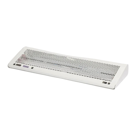
Sanuvox ASEPT.1X User manual

INSTALLATION INSTRUCTIONS FOR THE ASEPT.1XVersion A 11/2017
INSTALLATION QUESTIONS?CALL SANUVOX 1-888-726-8869Patent pending

INCLUDED ITEMSNOTES
G2INCLUDED ITEMSA.ASEPT.1X Unit (1)B. Cover (1)C. Lamps (2)D. Detectors (2)E. Screws (2)F. Gloves (1)G. Magnetic Contact (1)FDownloaded from www.Manualslib.com manuals search engine

CHOOSE APPROPRIATE INSTALLATION LOCATION
CAUTION Only certified electricians should be installing and maintaining this unit.The lamp change can be performed by regular maintenance staff. All other operations must be performed by trained and certified electricians. Please read instructions, name plates carefully.3Downloaded from www.Manualslib.com manuals search engine

INSTALLATION INSTRUCTIONS FOR THE ASEPT.1X
4Electrical wiring connection1. Choose which one of the 5 holes knock-outs will be used where your electrical connection will be inserted (3 in theback and 1 on each side) of the unit.2. Open accordingly (½ or ¾ inch npt).Unit mounting installation1. Drill 2 holes 31 inches apart center to center at a minimal distance of 8'' from the frame of the door.- For optimal performance the unit should be installed at a minimum of 84'' from the floor.2. Choose the appropriate (anchor) dowel and screws according to the type of surface that the unit is mounted to(concrete of gyproc). Insert the screws and leave 3/8 of an inch not tightened.3. Remove the cover by lifting straightforward : take care of the infrared dectectors.4. Insert the base of the unit on the screws previously mounted on the wall. Tighten the screws to make sure the unit issafely secured against the wall.5. The grey wire for the door interrupter is inside the base of the unit.
a. If the door interrupter is on the left hand side make sure to run the wire inside the unit all the way to the
left side and pull it out between the aluminum module and the white base of the unit.
b. If the door interrupter is on the right hand side make sure to run the wire inside the unit all the way to
the right side and pull it out between the aluminum module and the white base of the unit.
6. Install the door magnetic interrupter on the top of the door frame (same side as the door handle) as close as possible tothe door. (bottom of the frame).- Identical to an alarm system installation.7. Connect line black, neutral white and ground green to your electrical connection.
ONLY CERTIFIED ELECTRICIANS SHOULD BE INSTALLING THE UNIT.
8. Install the door magnetic contact on the door itself right the door interrupter that was installed on the frame of the door.a. Note that both pieces must be centered and aligned to one another.9. Install the cover on the unit (make sure that the motion detectors are clear when you are closing the cover).10. Install the lamps inside the unit.a. Please use the gloves supplied with the unit to manipulate the lamps in order not to leave any oil imprint on the
surface of the glass.
b. Remove the screw on the top side that holds the front grill and lower the grill towards the bottom of the unit.c. Insert the end of the lamp that has the rubber over the ceramic end cap in the hole on the right side of the unitand slide towards the right.i. Bring the lamp back towards the left and insert the pins in the connector.1. Note that the pins do not form a square but a rectangular, which leaves only 2 possible ways ofinserting the pins in the connectors.d. Repeat above steps for the second lamp.11. Close the grill and secure with the screw at the top of the cover.12. Turn the unit switch ON by pressing the switch on the top left corner.Downloaded from www.Manualslib.com manuals search engine

31 po.Unit mounting installation1. Drill 2 holes 31 inches apart center to center at a minimal distance of 8'' from the frame of the door.- For optimal performance the unit should be installed at a minimum of 84'' from the floor.
INSTALLATION : STEP BY STEP
52. Choose the appropriate (anchor) dowel and screws according to the type of surface that the unit is mounted to (concreteof gyproc). Insert the screws and leave 3/8 of an inch not tightened.
3. Remove the coverRemoving cover* Be carefull to not dammage the detectorsDownloaded from www.Manualslib.com manuals search engine

INSTALLATION : STEP BY STEP
66.7.4. Insert the base of the unit on the screws previously mounted on the wall. Tighten the screws to make sure the unit issafely secured against the wall.5. The grey wire for the door interrupter is inside the base of the unit.
a. If the door interrupter is on the left hand side make sure to run the wire inside the unit all the way to the
left side and pull it out between the aluminum module and the white base of the unit.
b. If the door interrupter is on the right hand side make sure to run the wire inside the unit all the way to the
right side and pull it out between the aluminum module and the white base of the unit.
6. Install the door magnetic interrupter on the top of the door frame (same side as the door handle) as close as possible
to the door. (bottom of the frame).
a. Identical to an alarm system installation.
7. Install the door magnetic contact on the door itself right the door interrupter that was installed on the frame of the door.
a. Note that both pieces must be centered and aligned to one another.

INSTALLATION : STEP BY STEP
7C.9. Install the cover on the unit (make sure that the motion detectors are clear when you are closing the cover).8. Connect line black, neutral white and ground green to your electrical connection.
ONLY CERTIFIED ELECTRICIANS SHOULD BE INSTALLING THE UNIT.

INSTALLATION : STEP BY STEP
8a.b.10. Install the lamps inside the unit.
a. Please use the gloves supplied with the unit to manipulate the lamps in order not to leave any oil imprint on the
surface of the glass.
b. Remove the screw on the top side that holds the front grill and lower the grill towards the bottom of the unit.
c. Insert the end of the lamp that has the rubber over the ceramic end cap in the hole on the right side of the unit
and slide towards the right.
i. Bring the lamp back towards the left and insert the pins in the connector.
1. Note that the pins do not form a square but a rectangular, which leaves only 2 possible ways of
inserting the pins in the connectors.
d. Repeat above steps for the second lamp.
11. Close the grill and secure with the screw at the top of the cover.12. Turn the unit switch ON by pressing the switch on the top left corner.Activating the unit1. Enter the room - close the door while remaining inside the room.a. Wait 15 seconds inside the room.2. Open the door.3. Exit from the room and close the door behind you.4. Close the door and Wait 90 seconds after which you may enter the room again and you will notice a blue light(indicating that the unit was ON and automatically cut-off when you entered the room interrupting thedisinfecting cycle).5. Look inside if the blade of the fan is still running.a. Note that even if the fan has stopped because the cycle was interrupted, the blades should still run fora few seconds after which they will stop completely.Downloaded from www.Manualslib.com manuals search engine
Other manuals for ASEPT.1X
1
Table of contents
Other Sanuvox Medical Equipment manuals